Elmer Verburg's Opposed Piston Engine 2 X Scale

Home Model Engine Machinist Forum

Help Support Home Model Engine Machinist Forum:

This site may earn a commission from merchant affiliate links, including eBay, Amazon, and others.

toolznthings

Project of the Month Winner
Joined
Dec 11, 2013
Messages
259
Reaction score
183
Location
Ohio
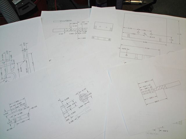
Found a new project in " Steam & Stirling " by Elmer Verburg. Decided to build the engine 2 X scale from original drawings with some modifications. Obvious starting point was to draw all the parts actual size in AutoCad LT and then scale up two times. Fastener sizes and other features are sized as work progressed.


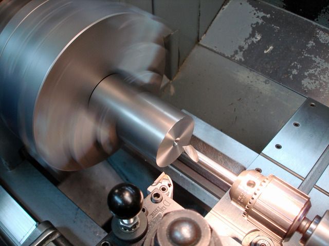
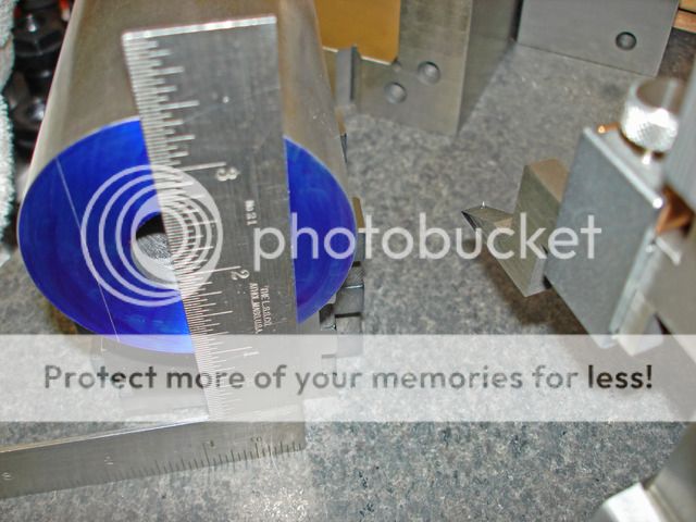
Will start with the cylinder that will be made from 12L14 round stock. Rough drilling thru the stock and taking a boring bar to do a short clean up for reference later.

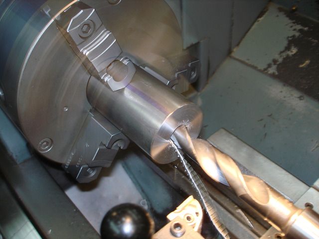
Spot drill and drill thru ....


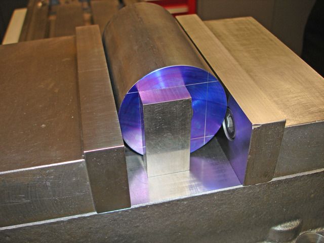
Next step is to rough square up the 1.500 x 1.500 x 4.000 long cylinder size leaving stock.
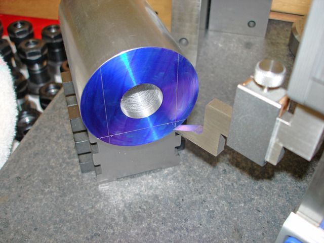
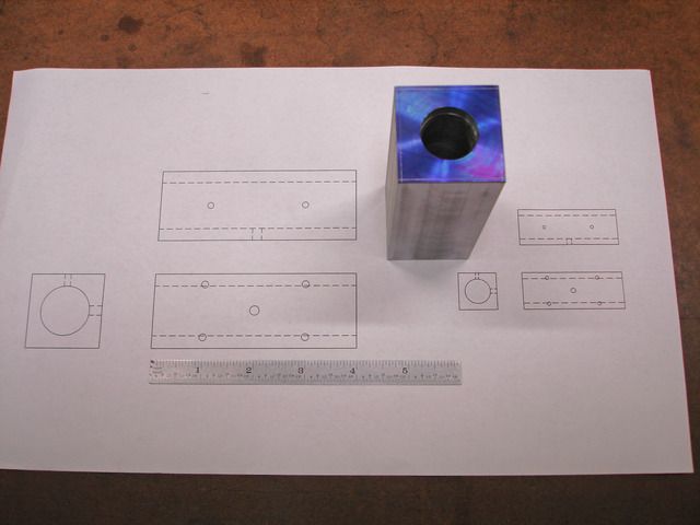
A quick layout for reference.


Set up at the mill lining up to the layout for the first milling cuts.


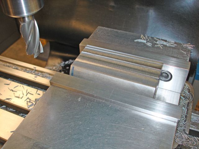
Continue the milling until the stock is roughed out.

 
After roughing the outside shape of the cylinder it is chucked in a four jaw and the clean up bore done earlier is indicated. And a quick check on the face.


The bore will be 1.000" which is twice the size from the original model.

Boring the cylinder ...


The approach I'm taking here is to machine the 1.500" square true to the thru bore rather than trying to true up the square to center the bore. A lot easier and more accurate IMO.
Back to the mill to set up the cylinder on a 1" bar resting on blocks setting on the mill table to machine the first side parallel to the bore. Depth mike to the rod.


First pass leaving about .005 grind stock.


Repeating this setup to finish the other sides leaving the .005 grind stock.
The cylinder is now square and true to the bore. I'm finishing on the surface grinder only to achieve a nice finish for later operations. Way less bench work later on. A good thing !


After grinding I set up the cylinder to finish the overall length of 4.000 "
And while the four jaw was still on the lathe I chucked up the cylinder to machine a 45 degree chamfer in each end bores.

Indicated vertical and mill the ends. Slight over hang in the vise to be able to mike the part length.


Cutting the chamfers.


At this point I reviewed the up scale drawing and decided on 8-32 tapped holes would be a reasonable size for the mounting holes.

Spot drill,tap drill and start the tap with the mill and finish tapping by hand.
Also drill the air inlet hole and the two exhaust holes in what will be the bottom of the cylinder when mounted to the column.


Work completed for now on the cylinder.
( View at left on the drawing is the original size of the cylinder. )


Toolznthings--please post a "General Arrangement" or overview of the engine you are building so that we have some idea what it is going to look like.---Brian
 
Hi Brian,

Can I take a snap shot of the picture in the book or is that a no,no ? There is a assembly drawing that would show the engine. I did not create a assembly drawing.

Brian
 
Last edited:
Take a picture of the book. That is not giving away any build details and you are not doing to make a profit from doing it.
 
Will be making a design change to the shape of the column that will be made from 6061-T6 bar stock.

Quick CAD layout to work from. The original column is drawn on the left side.


The bar stock is held in the vise on the stock edges so it will be milled long ways in the " Y " axis of the mill. Starting with 1" bar stock it will be milled to .750" thick. There is stock on the width of the column to be machined later. The bar was band sawed to rough width.

Milling the first side...


Part turned over and finishing to thickness .....


Milling the ends square to the face using the insert cutter. Established the overall height of 5.875". The width and shape of the column still has stock.

The next operation will be to rough drill and bore the 1.000' diameter hole for the main bearing.


Boring the hole to size ....


The 8-32 SHCS holes were drilled and counter bored to match the cylinder tapped holes.


Working from a pin in the main bearing bore I found center for the next operation to add 10-32 tapped holes in the end for mounting the column to the base plate.


Drilling and tapping the holes ....


Not shown here I added a 10-32 tapped hole to the bearing bore for a set screw that will hold the bearing in place. I want to be able to remove the bearing as needed. More work to come on the column in my next post.
 
Next operation will be to mill the outside shape of the column on the cnc mill.

Taking advantage of the 8-32 holes and the 1" bearing bore to mount the column to a fixture plate.
Drilling and tapping matching holes in the fixture plate. Picking up a existing hole to work from. ( fixture is do for a face cut )


Drilling and tapping for 8-32 screws ....


The fixture plate is mounted in the mill vise and the column is mounted using 8-32 shcs and indicated across the finished bottom to align the part straight.


After indicating the bearing bore for part zero a mill clamp was added to complete the setup.

Milling the outside ...


With the same setup I added some engraved contours to the column. A different pattern on the opposite side, also.


The machined results ....


Back to the mill to add the 10-32 tapped hole for the set screw to hold the main bearing in place and a setup on the opposite end to drill and ream the 5/32 air hole passage.

Tap drill, a clearance drill and 10-32 tap ...


The air passage from the top of the column to the bearing bore ...


Except for finishing work the column is complete ...

 
Hi,

I know that link. Thanks for posting for others who may not have seen the site.:)

Brian
 
Turning and boring the main bearing from some 660 bronze stock. The largest diameter will be 1.125" and 1.000" for a snug slip fit into the column. The overall length will be 2.250".

Starting with rough drilling thru and finish boring to .501" for the main shaft.

Boring the bearing ...


Checking the fit with the stock for the main shaft.


Turning the diameter for the fit into the column ...


A quick chamfer on the o.d. before turning the part around to finish the length and 1.125 diameter.


At the mill with a collet and indexer the inlet air fitting hole is drilled, spot faced and tapped 1/4-28 thread. The 5/32 air hole to match the column is drill and a flat for the set screw that will hold the bearing in place is milled.


The eccentrics are next on the list of parts. Made from brass they will be 1.120" diameter x .260 thick. There will be two pieces.
The 1.125 diameter was turned on the stock and held in the three jaw chuck setup at the mill and indicated. Offset for location the .375 hole was drilled and reamed and the .125 hole for a locating pin was drilled and reamed in the same setup.

Finding center ....


At the lathe the discs were parted off leaving stock to finish the .260 thickness.


After parting the parts were indicated in for the final face cut for thickness. The .260 width leaves clearance for the connecting rods.


The face cut ...


Finished eccentrics ...

 
The two eccentrics get three spacers made from 1/16" brass sheet and will finish 1.750" diameter. All three discs have a .375" reamed hole in the center and one disc will have a reamed .125" hole for the pin that will connect the eccentrics together.

Did a layout with dividers centered on a center punch mark leaving stock to be band sawed after drilling and reaming the holes.

Clamped to a block of melamine particle board held in the vise I picked up the punch mark for each disc.


Before drilling I stoned the cutting edges of the drill so it won't grab in the brass.


Drilling the center holes ...


After the mill work the discs were rough band sawed from the sheet.
At the lathe a arbor was machined to hold the discs for turning the outside diameter. A .375' diameter was turned to register the disc.


A large washer and schs hold the part for turning.


Except for some finishing work later on the discs are complete.
 
The two connecting rods will be made from brass bar stock. The overall length will be 3.375" long with the major diameter at 1.500" and a thru bore of 1.125" with clearance to be a running fit on the eccentrics.
The hardest part is the roughing the stock from the bar stock and allowing for warping after cutting from the bar stock. A trip to the hydraulic press was needed to correct some of the problem.

Finishing the blank thickness of .250" at one end and .563" at the far end leaving stock on the width and overall length.


The next operation was to drill and ream the .187" wrist pin hole and a reamed hole on center for the 1.125' bore to fit a 5/16" body shoulder bolt for the next operations.


Time to take that skin cut on the fixture plate before I use it for the connecting rod setup.


I modified the head on the shoulder bolt by machining it concentric to the body so I can indicate the head to find center of the 1.125" bore. A 10-32 shcs goes thru the wrist pin hole to hole the other end. Fixture in the vise at the cnc mill.


The first cuts on the connecting rod profile ...


The finished results ready for more machining ....


More machining at the manual mill in the next update.
Thanks for following along ! :)
 
Getting ready to bore the 1.125" diameter hole in the connecting rods. Using a small fixture plate with a piece of MDF as a backer. MDF ( medium density fiber board ) is very accurate and parallel on it's thickness and works well as long as it is not subjected to coolant.


Indicating the reamed hole for location ...


I made a turned disc with a stub to hold in the drill chuck so I could make a layout line 1.125" in diameter on the rod. This will allow me to free hand mill most of the stock from the rod with a end mill by observing the layout.


Marking the layout ...


Roughing out most of the stock ...


Finish boring the rod. I added a couple of clamps to the MDF to keep it in position for the next rod setup.


Making a setup to mill the .252" slot in the rod end for the rocker arms. Using a set of tall jaws in the mill vise and a couple of parallels. Balanced the vise with both rods and will mill both in one setup.


The slot is .252" wide and .688 deep so a necked 3/16" end mill was used to rough and finish the width.

Roughing on center to depth ...


Finish milling the width ....


One last setup to add a 1/16" corner radius to the rod ....


Finished except for 1-72 tapped hole for wrist pin retention set screw and a hole for oiling to be done later.

 
The connecting rod that goes from the pistons is 1.906" long and .500' wide at the large end and .250" where it connects to the pistons. The wrist pin hole at the piston is .125 diameter and .187" diameter at the slotted end.

At the cnc mill the profile is milled from a larger piece of brass at a depth greater than the finished thickness of .375".


After machining two parts the profile is band sawed from the stock and set up at the mill to establish the .375" thickness. Short overhang at the vise to measure the thickness.


The next setup does the .187" and .125" reamed holes.


Doing the .252 wide end slot x .625" deep.


Finished except for the 1-72 tapped holes at the slotted end to add a set screw to hold the pivot pin in place. Bench work for finish later on before assembly.

 
The two pistons are 1.000" in diameter by 1.125" long and made from brass.
Turning the outside diameter for a slip fit to the cylinder bore and facing one end.


Machining the two counter bores. One bore is .500" x 1.000" deep and the second is .813" x .438 deep.


After parting off from the rouch stock the overall length was finished.


At the mill I decided to mill a square shaped pocket past the wrist pin location so I could add spacers on each side of the short connecting rod to keep it centered.


The next setup was to indicate the flat on one side of the internal square to have the .125" wrist pin hole at 90 degrees to the machined internal square pocket.


Drilling and reaming the wrist pin hole back .563" from the piston end.


This picture shows the pistons finished except for some v-grooves for oil that will be added later. The drawing they are pictured with was before I changed the shape of the internal square cutout. ( the two don't match here, engineering on the fly :eek: )


The piston with the spacers made and a 1/8" dowel pin for the wrist pin.


A trial assembly with a updated drawing ...


Decided to do the base plate for the engine next. .750" thick x 4.125" wide x 6.000" long. It has two drilled and counter bored holes for 10-32 shcs and a access hole for the 10-32 set screw in the column that holds the main bearing in place. Not shown are two 10-32 tapped holes on the front edge for the rocker arm pivots.

 
The rocker arms are machined from .250" brass bar stock. Overall length is 6.125" and .625" wide. The bottom pivot hole will be .313 and the two other pin holes will be .188".

Preparing the brass blank to be mounted on a fixture plate for cnc milling the outside contour.


Drilling the fixture with hole locations to match the finished holes in the blank.
A modified shoulder bolt will be used to establish part zero.


Mounted to the fixture at the cnc and indicating the shoulder bolt.


The finished machined rocker arm. Bench work later on before assembly and a couple of oiling holes will be added.

 
Machining the .500" x 5" long main shaft. After threading the one end with a 3/8"-24 thread the shaft was setup in the indexer to mill the flats that control the air flow in and out of the engine. A pre-drilled hole on the threaded end provides a exhaust outlet and one flat will be milled and a cross hole drilled to this hole.
Used a end mill to cross drill ...


A longer flat for air into the column thru the main bearing is milled 180 degrees to the first flat.


A better view of the setup ...


Not shown here, I milled a 7/16" hex on the end of the shaft at the fly wheel
end for a wrench to hold the shaft at assembly when locking the eccentrics in place at the opposite end.

The fly wheel is 4" in diameter x 1" wide at the rim and has a extended hub for a 10-32 set screw. Overall width with the hub is 1 1/2" long.

Boring the thru hole for the .500 shaft ...


Doing the hub end first and profiling the center. The opposite side was machined the same.


The brass air hose fitting that screws into the main bearing. Drilling the thru hole and turning the od. The end that goes into the bearing has 1/4"-28 threads.


The opposite end gets a 3/8"-28 thread and a drilled and counter bored .234" diameter x 1/4" deep hole for the air hose seat.


Set up at the mill wrench flats were milled on the fitting ....

 
Here is the parts with the finish work completed. Oil holes and set screw holes added where need. Ready to do the assembly.


The base plate with 45 degree chamfer on the edges and painted. The column and cylinder with my logo engraving done. The fly wheel painted and polished with a decorative groove added to the rim.


To plug the air passage drilled hole in the column I made a plug at the lathe and cnc mill and modified the hole at the column top.


Held in place with a couple of 5-40 button head screws.


Assembled the column to the base with the cylinder and main bearing. The air passage plug in place with the year engraved in the face.


With the main shaft in place the eccentrics and connecting rod get assembled. The 1/8" dowel pin connects the eccentrics in the correct position.


Eccentrics to the rocker arms with the pins and set screws.


Should have taken some more assembly pictures, but here is the engine all together and mounted to a oak base. A name tag giving credit to Mr. Verburg and build info will be added later.


Here is a link to the engine running. THANKS for the views and likes and I hope everyone enjoyed the build. :)

https://youtu.be/r3i1Bl3CAks
 

Latest posts

Back
Top