- Joined
- Oct 1, 2010
- Messages
- 1,342
- Reaction score
- 395
Back in April I first thought about building Elmer Verburg's No. 33 Mill Engine at 150 percent size, so that it would be a little larger with about a 4.5-inch. flywheel. Once that decision was made, I sat down with the drawings from john-tom.com and starting planning. I had forgotten that Elmer liked fractional inches.
A few days later I ended up deciding that I might as well go through Elmer's drawings for and change the measurements to decimals, then figure out the sizes for the one-and-a-half sized version. I needed to determine what materials to order as well.
I digress a little here to explain that I used to have a techie job where I prepared proposals for installations, interpreting someone's needs to plans and specs, and ultimately to purchase orders and contracts. So it looks like a spreadsheet will get made and I'll decide how to name documents and everything.
So, I have also made the decision to show a lot of this stuff in the log as some of the newcomers to the hobby may find it useful. It is also going to be important for me to be organized as I expect to take a while to get this project done: I expect that I will be diverted by family caretaking, home improvements, and some other shop projects and tooling builds. I am afraid that there will be some of that "excrutiating minutiae" in this thread.
I have considered a parallel thread which summarizes and highlights the progress, perhaps in another place. This would be for those who may want to know how this progress is going, but without so many updates.
The first step is the spreadsheet I made to get an idea of materials. The second page looks like this:
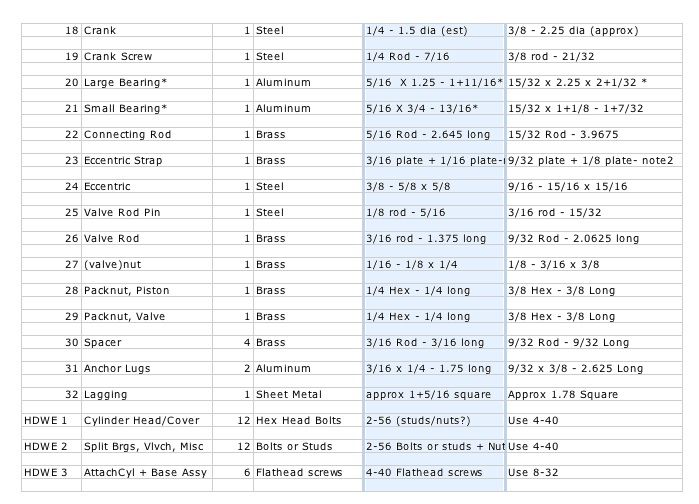
I took this out to my shop and determined what I had in stock and what would need to be ordered. I also made two other decisions at this stage. I will buy flywheel castings, because I think they will look "right" on this engine and I already have enough parts to make. I don't know how it will go with castings, but I can also change my mind if I want. I also decided that I will use unstudly studs made from threaded rod, instead of screws or bolts. Adding some tools and miscellaneous items to the fastener hardware and metal stock needed for this project, and some others, resulted in orders out to three places. I will probably also have to get some more cutters before I am done, but that can wait.
--ShopShoe
A few days later I ended up deciding that I might as well go through Elmer's drawings for and change the measurements to decimals, then figure out the sizes for the one-and-a-half sized version. I needed to determine what materials to order as well.
I digress a little here to explain that I used to have a techie job where I prepared proposals for installations, interpreting someone's needs to plans and specs, and ultimately to purchase orders and contracts. So it looks like a spreadsheet will get made and I'll decide how to name documents and everything.
So, I have also made the decision to show a lot of this stuff in the log as some of the newcomers to the hobby may find it useful. It is also going to be important for me to be organized as I expect to take a while to get this project done: I expect that I will be diverted by family caretaking, home improvements, and some other shop projects and tooling builds. I am afraid that there will be some of that "excrutiating minutiae" in this thread.
I have considered a parallel thread which summarizes and highlights the progress, perhaps in another place. This would be for those who may want to know how this progress is going, but without so many updates.
The first step is the spreadsheet I made to get an idea of materials. The second page looks like this:
I took this out to my shop and determined what I had in stock and what would need to be ordered. I also made two other decisions at this stage. I will buy flywheel castings, because I think they will look "right" on this engine and I already have enough parts to make. I don't know how it will go with castings, but I can also change my mind if I want. I also decided that I will use unstudly studs made from threaded rod, instead of screws or bolts. Adding some tools and miscellaneous items to the fastener hardware and metal stock needed for this project, and some others, resulted in orders out to three places. I will probably also have to get some more cutters before I am done, but that can wait.
--ShopShoe