Could be long - go get a coffee.
Right ready ?
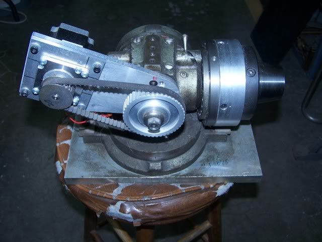
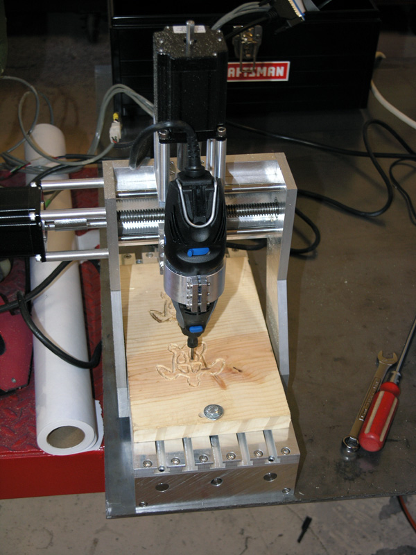
First off Gail's method and the ones on the Division master forum are the way to go. The one in the video in the first pic isn't a good idea and it's direct drive and the average stepper motor doesn't have enough detent torque to hold it accurately in position when parted. If you select microsteps to smooth it out that also reduces torque.
A worm and wheel drive of greater than 20:1 is required if the drive has to stop being reverse driven.
Dividing heads, rotary tables and even propitiatory off the shelf gearboxes make good 4th axis to give them one correct name.
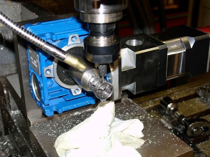
Here's one setup for use on a Taig.
Just a hollow shafted gearbox driven by a stepper thru an Oldham coupling, this one has a 14mm output shaft to give an idea on size.
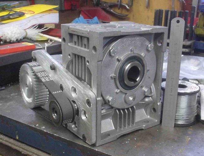
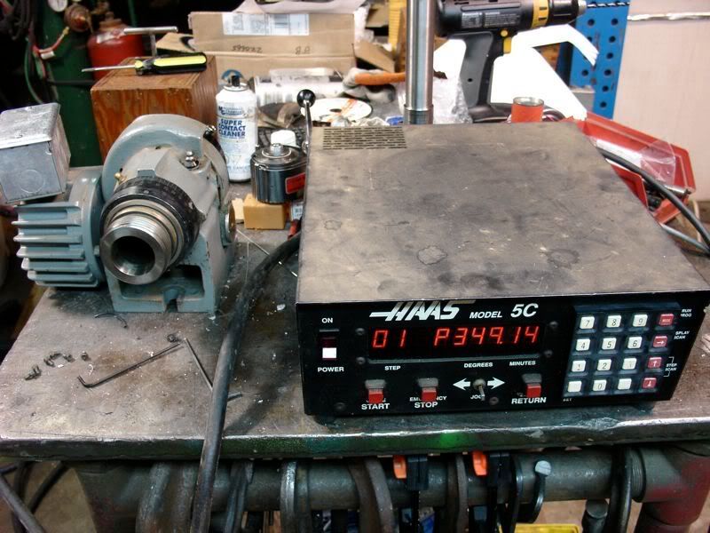
They come in all sizes and this one off my electronic hobber has a 25mm shaft size.
Build up of these heads / tables etc is very simple, a stepper mounting and a metod of driving the work usually thru a coupling to remove any mis-alignment.
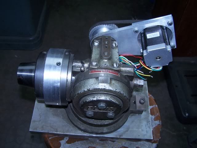
Here is one part done, the handwheel has been replaced with a drive dog that has thrust bearings inside it.
Simple enough job to do, anyone who can make a small engine has enough skills to do this purely mechanical conversion.
Here is one of those little 3" tilting rotabs that's been converted.
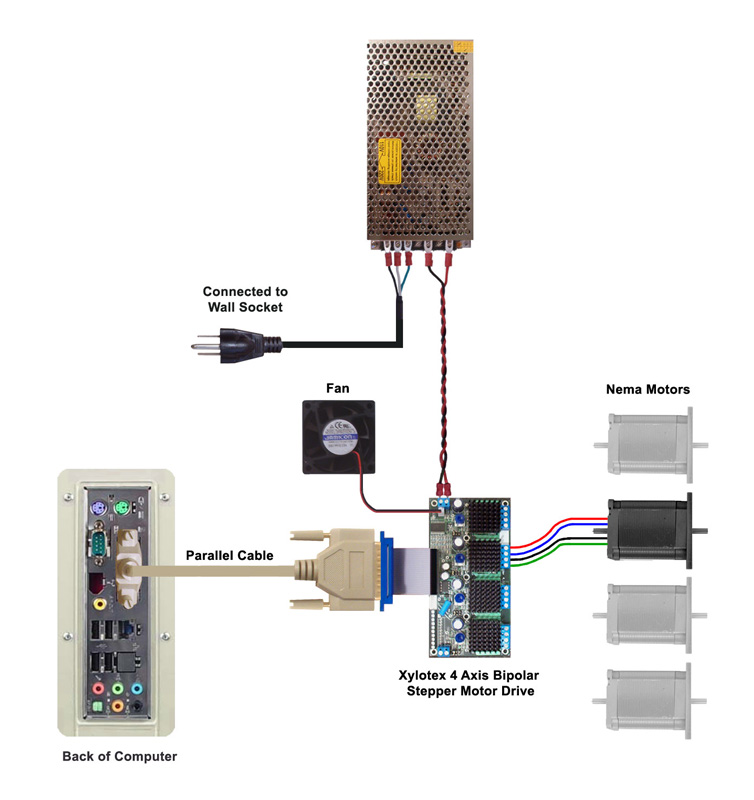
That takes care of the mechanics, next is the power supply and then the controller.
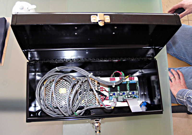
Power supply is just a transformer, large capacitor and a bridge rectifier, literally but we'll cover this in another post if there is enough demand.
Controller.
Can be varied.
PC based using a full CNC program like Mach 3 or TurboCNC
PIC based using something like the Division master down to small simple pulse generators.
There are even a couple of programs that run on the PC just to run a rotary table or dividing head for gearcutting or indexing
So depending on skill levels and equipment you can get a working 4th axis going for not much outlay.
.