
You are using an out of date browser. It may not display this or other websites correctly.
You should upgrade or use an alternative browser.
You should upgrade or use an alternative browser.
Edwards Radial 5 Build
- Thread starter LADmachining
- Start date


Help Support Home Model Engine Machinist Forum:
This site may earn a commission from merchant affiliate
links, including eBay, Amazon, and others.
- Joined
- Jun 12, 2012
- Messages
- 88
- Reaction score
- 68
Aloha everyone --
All the best intentions here in Hawaii to get back rolling with my Radial. Just having to knock a little Reality back into line.
Lantain82, whoever you are, that's a magnificent piece of work. Brian's a lucky lad to have you as a neighbor. I've marveled at those Bentleys for a while, trying to imagine just what they must sound like...also trying to picture what must be going on with all those gases flowing around inside, with all that centrifugal force going on. Don't they mind at all?
Brian, thanks so much for the step-by-step of the pipe-bending. As you may recall I got one of those bending machine kits from Hemingway, but it's still in the box, and will be until it's bending-time.
As things are I'm happy enough now with the bottom-end assembly to move on to the Cylinder Heads. Of course I hadn't ordered enough material to follow Brian's sensible example and make a sacrificial head, just to get the hang of things, so of course I trashed one immediately (by over-turning the combustion chamber) so now I'm waiting for a re-supply of 2" 7075. In the meanwhile I've been fabricating the head-milling fixture so successfully developed by the original LAD (founder of this thread):
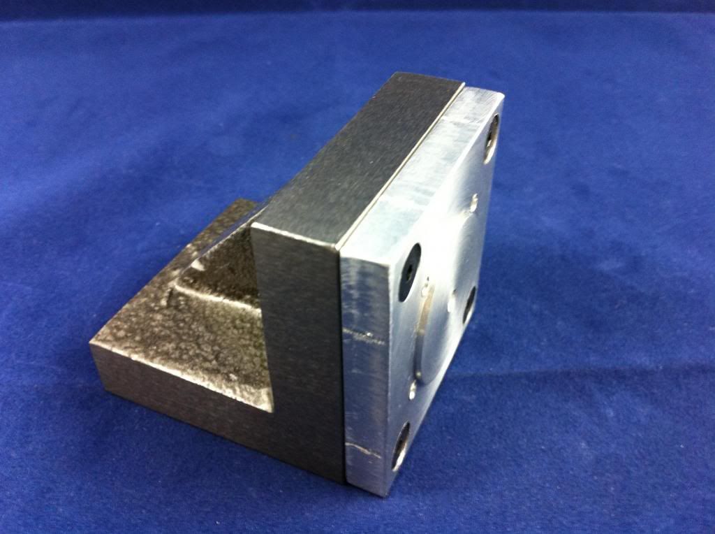
It's made per The LAD, just 1/4" aluminium plate screwed to a small angle fixture, with a nub turned on its face the same diameter as the recess cut into the bottom of the heads and some tapped holes to correspond to the head/cylinder screws. So of course now I'm really excited about getting all those fancy angles cut on the head blanks using this device, but I shan't start that part of it till my new supplies arrive, and I can get a couple more blanks cut. That's maybe the biggest drawback of living out here, where shipping doubles the price of stock, and quadruples the time it takes to get ahold of. Not that I'm complaining mark you -- I've been painfully aware of the extremes endured lately by HMEM correspondents in, say, chilly Ontario and warmish New South Wales. Honolulu may be a scruffy sort of place (road maintenance is as yet an undiscovered art, for example) but we're not too often inconvenienced by weather.
Brian, whatever became of that radial-powered plane that landed in your 'hood?
Happy chipping, everyone.
All the best intentions here in Hawaii to get back rolling with my Radial. Just having to knock a little Reality back into line.
Lantain82, whoever you are, that's a magnificent piece of work. Brian's a lucky lad to have you as a neighbor. I've marveled at those Bentleys for a while, trying to imagine just what they must sound like...also trying to picture what must be going on with all those gases flowing around inside, with all that centrifugal force going on. Don't they mind at all?
Brian, thanks so much for the step-by-step of the pipe-bending. As you may recall I got one of those bending machine kits from Hemingway, but it's still in the box, and will be until it's bending-time.
As things are I'm happy enough now with the bottom-end assembly to move on to the Cylinder Heads. Of course I hadn't ordered enough material to follow Brian's sensible example and make a sacrificial head, just to get the hang of things, so of course I trashed one immediately (by over-turning the combustion chamber) so now I'm waiting for a re-supply of 2" 7075. In the meanwhile I've been fabricating the head-milling fixture so successfully developed by the original LAD (founder of this thread):


It's made per The LAD, just 1/4" aluminium plate screwed to a small angle fixture, with a nub turned on its face the same diameter as the recess cut into the bottom of the heads and some tapped holes to correspond to the head/cylinder screws. So of course now I'm really excited about getting all those fancy angles cut on the head blanks using this device, but I shan't start that part of it till my new supplies arrive, and I can get a couple more blanks cut. That's maybe the biggest drawback of living out here, where shipping doubles the price of stock, and quadruples the time it takes to get ahold of. Not that I'm complaining mark you -- I've been painfully aware of the extremes endured lately by HMEM correspondents in, say, chilly Ontario and warmish New South Wales. Honolulu may be a scruffy sort of place (road maintenance is as yet an undiscovered art, for example) but we're not too often inconvenienced by weather.
Brian, whatever became of that radial-powered plane that landed in your 'hood?
Happy chipping, everyone.
Last edited:
Brian-in-Oz
Retired Swarf Maker
- Joined
- Mar 8, 2013
- Messages
- 137
- Reaction score
- 133
G'day Michael and all,
Great to see you back into the Edwards Michael - have you finished your micro drill press yet? I would like to see the finished product.
Interestingly I to faced the same situation with the supply of 2" 7075 Aluminium.
I first purchased from Speedy Metals as I could not find a supplier of 7075 in Australia (everyone has 6061) but the freight is the killer. I needed some more 2" 7075 (read sacrificial headS - as in plural) and after much searching found a supplier in Melbourne. The catch was though that they didn't cut and would only supply in a three metre length however it only worked out at about the same price as importing 2 X 1 foot lengths from the States when freight was included. Yes! you guessed it - I now have plenty of 2" 7075 for future projects.
Unfortunately I never did get to see the Stinson Reliant start up as it happened on a Sat. (my golf day) but it did do some passes over the golf course while I was playing and sounded very sweet.
It's funny how some of the seemingly most simple parts of a project can turn out to be problematical and those pesky little inlet and exhaust flanges had me worried. Doing them individually would drive you to drink so I had to come up with a plan to make them all at once. This is what I did.
Turned a piece of 1" brass bar to .900" and drilled a centre hole to fit the brass tube and then parted off 20 odd "washers" .060" thick. I decided to make the flanges of brass instead of the steel as shown in the plans as brass is much easier, quicker and safer to part off than steel but to make them .060" thick rather than the .040" as per plan. I am confident this will be OK. I then placed all of the "washers" onto the mandrel I made as shown in photo and did the nut up real tight so it acted like a solid brass bar and drilled the mounting holes and then milled to shape using the rotary table to give consistent angles. The end and side radii were achieved with a good old fashioned file - undo the nut and presto - a bunch of flanges all at once total time about two hours.
The next step is to make some jigs to hold the tube and flanges in alignment while they are silver soldered. The exhausts will be simple enough but the inlet jig will need to be very precise.
Some years ago my wife and I drove around the perimeter of O'ahu and I don't remember the roads being that bad - what I do remember though is being lined up by the local kids as we approached any bridge over a river - creek and they jumped en-mass into the water to make a huge splash to drench us. We were in a rented convertible (Pontiac Sunbird I think - gutless) so we were fair game but all good fun.
Cheers for now - Brian Rof}
- Joined
- Jun 12, 2012
- Messages
- 88
- Reaction score
- 68
That's a terrific approach to making the pipe flanges, Brian. So much better than making them one at a time and I'm sure making them of brass instead of steel will make for a prettier result.
On this end, 7075 reinforcements have arrived and a couple more head blanks are waiting to have their combustion chambers scooped out. Then it'll be fun and games on the mill for the next thirty-odd years (all those set-ups!). Brian, I recall that you made your screw-in valve guides before machining your heads. The way I'm going I'll probably finish the heads before turning the guides...unless there's a problem with that?
The micro drill press is coming along, but even more slowly than the Radial...remember, it's just a therapy project to help stop me taking a hammer to the Radial in those too-passionate "DUH!!!" moments. That said, a few more pieces have been added, and I should have the quill assembly done by the weekend. I'm also looking around for a suitable brushless motor.
So sorry you missed the Stinson. Every now and again I'll spot the radial-powered Bellanca in the sky over Honolulu taking some other lucky bugger for a ride...but I always hear it before I see it. Beautiful thing. I'm sure if Beethoven had lived just a little bit later he'd have written a Concerto for 9-Cylinder Radial and Orchestra.
Here's a pic of my partially-assembled puppy...five rods, three pistons, one cylinder. Most of the other bits are around somewhere, and the heads are in a State Of Becoming...
More soon I hope.
m
On this end, 7075 reinforcements have arrived and a couple more head blanks are waiting to have their combustion chambers scooped out. Then it'll be fun and games on the mill for the next thirty-odd years (all those set-ups!). Brian, I recall that you made your screw-in valve guides before machining your heads. The way I'm going I'll probably finish the heads before turning the guides...unless there's a problem with that?
The micro drill press is coming along, but even more slowly than the Radial...remember, it's just a therapy project to help stop me taking a hammer to the Radial in those too-passionate "DUH!!!" moments. That said, a few more pieces have been added, and I should have the quill assembly done by the weekend. I'm also looking around for a suitable brushless motor.
So sorry you missed the Stinson. Every now and again I'll spot the radial-powered Bellanca in the sky over Honolulu taking some other lucky bugger for a ride...but I always hear it before I see it. Beautiful thing. I'm sure if Beethoven had lived just a little bit later he'd have written a Concerto for 9-Cylinder Radial and Orchestra.
Here's a pic of my partially-assembled puppy...five rods, three pistons, one cylinder. Most of the other bits are around somewhere, and the heads are in a State Of Becoming...

More soon I hope.
m
Brian-in-Oz
Retired Swarf Maker
- Joined
- Mar 8, 2013
- Messages
- 137
- Reaction score
- 133
Hi Michael and all Radial Engine Worshippers :bow:
Edwards is looking great Michael - how are the heads coming along.
I am currently away baby sitting the grand kids so no workshop for a few weeks.
When I get home I hope I can finish my Edwards Radial in a few weeks as I only have the inlet tubes ( I think these are going to be real fiddly ) and prop. boss to do. Then I will have to organise an oil tank and engine mount and glo driver before finally seeing if it will run.
Cheers Michael and all - :wall:
- Joined
- Jun 12, 2012
- Messages
- 88
- Reaction score
- 68
Aloha Brian & Radialeros all --
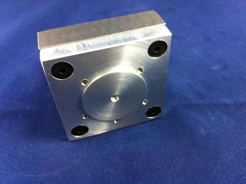
Anything anyone has ever said about the labor-intensiveness of the Edwards' cylinder heads wasn't exaggerating. Very time consuming process, which gets even more so as you get more cautious, not wanting to waste the investment made so far. But -- so far, so good. All the boring and counterboring and tapping and scooping seems to have been accomplished to specs, so now it's all over bar the fin-nishing.
Making 0.030" cuts with a 0.040" slitting saw seems to produce a nice result. After much deliberation I decided to space the fins 0.080" apart, same as those on the cylinder barrels, not because I think it'll aid the cooling -- which I'm sure it won't -- but, just because I liked the look of it. So there.
Here's an in-progress piece, still a little rough around the edges...
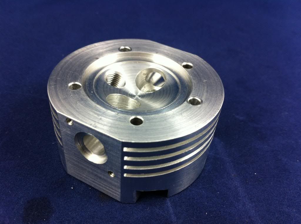
Next stop, of course, will be cutting the fins on the top of the heads, then fabricating the valve guide inserts (bronze or brass, haven't decided yet), making some valves, and fashioning some sort of cutter for the valve seats.
As one of the sages on this site says, every day a little piece, sometimes the same little piece...
Brian, I'm sure you're a terrific grandfather, but you must be going crazy playing tiddlywinks with toddlers when a completed Radial 5 is just a few pieces of piping away. I know I would be.
All best everyone...
m
Anything anyone has ever said about the labor-intensiveness of the Edwards' cylinder heads wasn't exaggerating. Very time consuming process, which gets even more so as you get more cautious, not wanting to waste the investment made so far. But -- so far, so good. All the boring and counterboring and tapping and scooping seems to have been accomplished to specs, so now it's all over bar the fin-nishing.

Making 0.030" cuts with a 0.040" slitting saw seems to produce a nice result. After much deliberation I decided to space the fins 0.080" apart, same as those on the cylinder barrels, not because I think it'll aid the cooling -- which I'm sure it won't -- but, just because I liked the look of it. So there.
Here's an in-progress piece, still a little rough around the edges...

Next stop, of course, will be cutting the fins on the top of the heads, then fabricating the valve guide inserts (bronze or brass, haven't decided yet), making some valves, and fashioning some sort of cutter for the valve seats.
As one of the sages on this site says, every day a little piece, sometimes the same little piece...
Brian, I'm sure you're a terrific grandfather, but you must be going crazy playing tiddlywinks with toddlers when a completed Radial 5 is just a few pieces of piping away. I know I would be.
All best everyone...
m
- Joined
- Jun 12, 2012
- Messages
- 88
- Reaction score
- 68
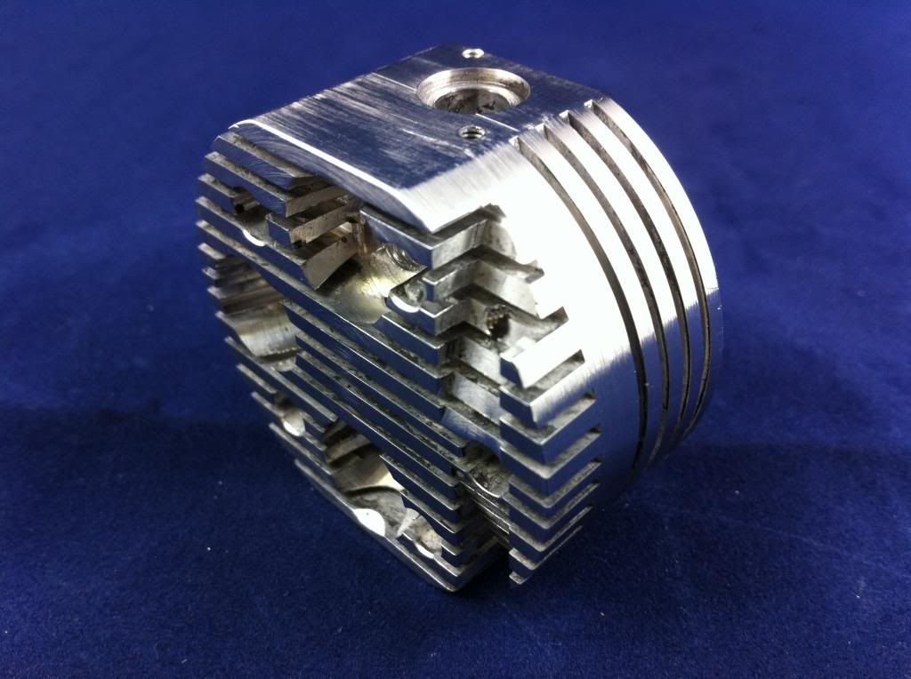
First head actually achieved, fins and all. Others on the way within days, I expect, since their short back and sides is the only operation left. But then I'm afraid there has to be a short interlude while I overhaul my little Grizzly lathe...as soon as I started setting up to make some valves it became apparent how out-of-true it's become. Less than perfection on this little engine will never do. Anyway, here's Head #1:
More soon I'm sure.
m

More soon I'm sure.
m
- Joined
- Jul 16, 2007
- Messages
- 2,987
- Reaction score
- 1,055
Michael,
You're absolutely correct on the amount of time it takes to make a head, or in your case 5 heads. When I made the heads for my engine I went through all the same processes that you did, roughing, finishing, finning, guides and seats. Before you know it you'll have them finished and you can take a deep breath and relax.
gbritnell
Brian-in-Oz
Retired Swarf Maker
- Joined
- Mar 8, 2013
- Messages
- 137
- Reaction score
- 133
Your heads are coming along nicely Michael - and yes I am going crazy not being able to get stuck into bending those last few bits of pipe.
As for playing tiddlywinks with the grandkids these modern kids wouldn't know what they are. They don't seem to be happy unless they've got an iPod or iPhone within reach and Gramps duties is more like chasing an out of control RC helicopter across the neighbourhood rooftops. When I get home my workshop is going to be like a temple of utter serenity.
Anyhow - keep at those heads - I am looking forward to seeing all five completed.
Cheers Michael and all. :rant:
- Joined
- Jun 12, 2012
- Messages
- 88
- Reaction score
- 68
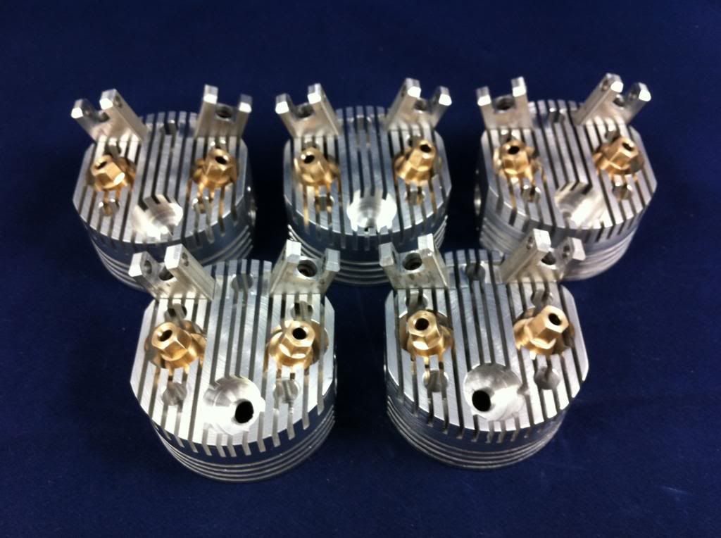
Five heads, all kitted out with valve guides and rocker supports. Valve train is next -- pushrods, rocker arms, cam followers, valves, all that -- before the last rough assembly to make sure everything works when it's supposed to in relation to everything else. And oh yes, a valve seat cutter, I'll be needing to make one of those too.
Then, it should be down to things like gaskets and carburetion and some sort of ignition, and see how many places the oil squirts out. Hmmm. Shouldn't take more than another eon or two.
Something that's puzzling me...I bought a set of Fox "long" glowplugs, as specified, but they seem so tiny when I put them in place. The thread's ok, but the business end of the plug is at least 3/16" shy of the end of the threaded hole when screwed all the way in. Also the plug body just seems so titchy in that great big countersunk hole, like a fire hydrant at the bottom of the Grand Canyon. Do I have the wrong plugs I wonder?
Hope you've survived your babysitting duties, Brian. How's them pipes?
All best,
m
Brian-in-Oz
Retired Swarf Maker
- Joined
- Mar 8, 2013
- Messages
- 137
- Reaction score
- 133
Hi Michael and all,
The heads look great Michael - when I looked at the photo of them I couldn't help thinking they looked like five faces with ears pricked up, eyes boggled and a mouth exclaiming ohww! I'm glad that's over. I know just how you feel now that they are finished.
I also purchased the Fox long gloplugs (with idle bar) as specified in the plans and I know what you mean when you say they they look a bit lost when in position but I am am sure this must be OK. I intend to purchase an automatic glo driver that provides current to the plugs only when needed. I guess when we actually get to the point of trying to get our engines to run we will enter a whole new area of problem solving.
I am still on baby sitting duty in Newcastle but head for home on Friday with even less hair (a two day drive) and intend to spend 24/7 in the workshop next week and will keep information flowing as to success or otherwise with the inlet tubes.
Cheers for now Michael and all from Brian in Oz. :big:
- Joined
- Jun 24, 2010
- Messages
- 2,361
- Reaction score
- 931
..I bought a set of Fox "long" glowplugs, as specified, but they seem so tiny when I put them in place. The thread's ok, but the business end of the plug is at least 3/16" shy of the end of the threaded hole when screwed all the way in. Also the plug body just seems so titchy in that great big countersunk hole, like a fire hydrant at the bottom of the Grand Canyon. Do I have the wrong plugs I wonder?
m
I'm kind of intrigued by this. I don't have any Fox brand plugs to measure myself, but I seem to recall 2 basic lengths, long & short. Eyeballing what I think is a long plug picture & using ~1/4" diameter thread as a visual measurement guide, guessing the threaded apportion is ~0.25" long as well <less> the copper washer & maybe [plus] idle bar? The Edwards section view looks like it calls for 0.25" threaded length? But I guess that's the minimum distance relative to piston because the combustion chamber is a cone. So the fore/aft edges of the plug would be inside the cone by some amount. Is this what you mean?
Or maybe I'm misunderstanding & you mean the 0.5" counter bore to accommodate the socket wrench over the hex to tighten/loosen plug?


- Joined
- Jun 12, 2012
- Messages
- 88
- Reaction score
- 68
Gentlemen --
Brian, its always a temptation to anthropomorphize our little creations (stroking the aluminum, "how are you this mornin' Sadie, a little less snarly perhaps, ready to take a drop of kerosene coolant today without spittin' at yer ol' man...?") But I just loved your descriptions of what my heads were saying to you. So animated and human and needy. But then I'm in downtown LA just now, and I've seen any number of faces jUst this evening that could fit that description.
Petertha, thanks for your observations...I'm going to measure up .that whole cast of characters when I get back, and let you know.
m
Brian-in-Oz
Retired Swarf Maker
- Joined
- Mar 8, 2013
- Messages
- 137
- Reaction score
- 133
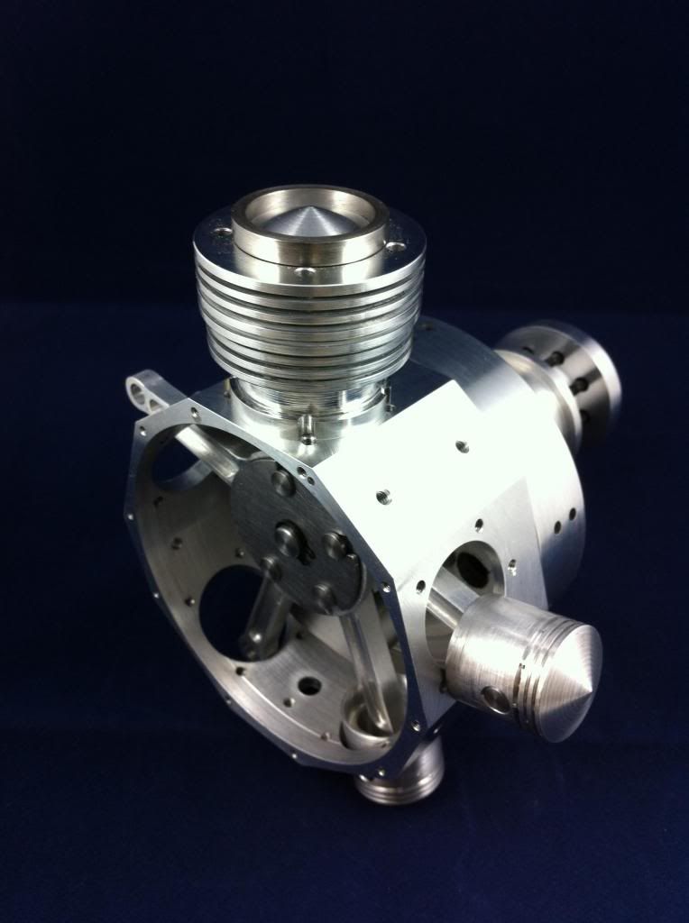
Hi Michael and all of HMEM
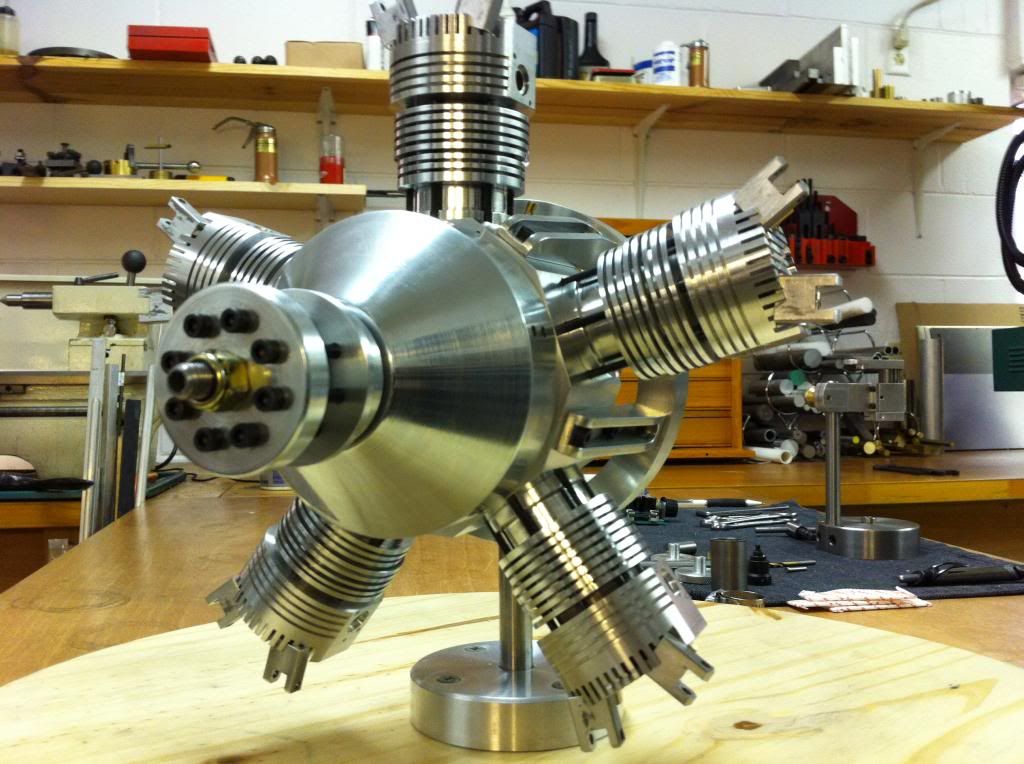
after a month of looking after the grandkids I am finally back in the sanctity of my workshop. First job was to make a jig to hold the exhaust pipe and flange in the correct alignment while silver soldering them. All went well and the things that hopefully will produce that lovely radial symphony are now bolted in place.
Perhaps the German language anthropomorphises (now you've taught me a new word Michael I can't help but use it) our engines as there is no direct translation for radial engine as they call it a sternmotor i.e translated - a star engine.
The inlet tubes are next and an accurate jig will be need as they have to fit precisely on both ends not like the exhausts that just have to bolt on and can point almost anywhere.
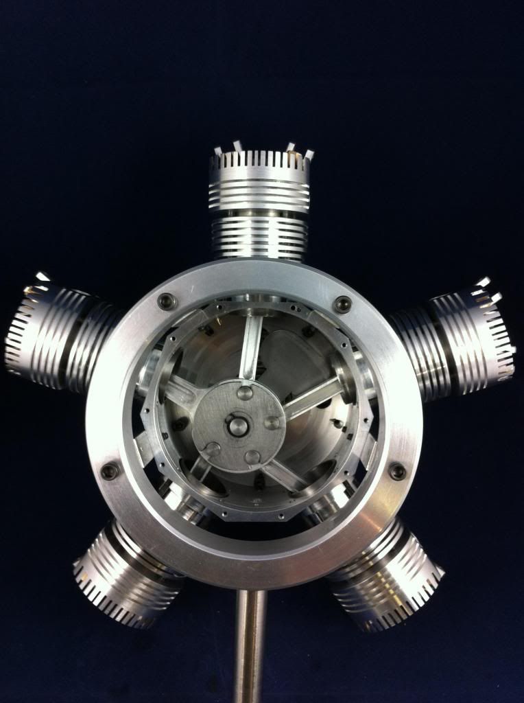
In case anyone is wondering the round boss in the middle of the engine is just to hold it while working on it - this is where the inlet manifold bolts on.
Cheers all - Brian scratch.gif


after a month of looking after the grandkids I am finally back in the sanctity of my workshop. First job was to make a jig to hold the exhaust pipe and flange in the correct alignment while silver soldering them. All went well and the things that hopefully will produce that lovely radial symphony are now bolted in place.
Perhaps the German language anthropomorphises (now you've taught me a new word Michael I can't help but use it) our engines as there is no direct translation for radial engine as they call it a sternmotor i.e translated - a star engine.
The inlet tubes are next and an accurate jig will be need as they have to fit precisely on both ends not like the exhausts that just have to bolt on and can point almost anywhere.
In case anyone is wondering the round boss in the middle of the engine is just to hold it while working on it - this is where the inlet manifold bolts on.
Cheers all - Brian scratch.gif
LADmachining
Well-Known Member
- Joined
- Sep 22, 2009
- Messages
- 53
- Reaction score
- 11
That is looking excellent Brian - I am inspired to get out in the workshop and get working on my one! ")
Anthony
Anthony
- Joined
- Jun 12, 2012
- Messages
- 88
- Reaction score
- 68
Welcome back to the Land of Swarf, Brian, and congratulations on your (as always) first-rate work. Your collection of parts is beginning to take on a most engine-like appearance, and pretty soon I expect to be able to hear it roar from here.
My collection of parts still looks like a collection of parts, however, and I haven't been adding much to it lately since I've got my lathe torn apart for tuning, and in between things I've been nibbling away at my micro-drill press project. Which makes your creation all the more humbling.
BTW I'm not sure if this shows up on your screen but, as one of the by-products of HMEM's recent expansion of advertising activities, both of your pictures have interesting captions: the second is headlined "Brain Training Games," and urges us all to "challenge [our] memory and attention with scientific brain games." Pretty appropriate, I thought. But the first picture is captioned "The Fountain of Youth," which struck me as well-intentioned though perhaps a bit of an exaggeration.
Best all,
m
Brian-in-Oz
Retired Swarf Maker
- Joined
- Mar 8, 2013
- Messages
- 137
- Reaction score
- 133
Hi Anthony - thanks for your comments and interest.
It was your original posts that got me going on the Edwards in the first place.
If Michael and myself can inspire you to get back into your workshop and finish yours that would be great, however as much as we love making swarf Parenting (and Grand Parenting) comes first.
Cheers and keep us in touch with your progress - Brian Thm:
Brian-in-Oz
Retired Swarf Maker
- Joined
- Mar 8, 2013
- Messages
- 137
- Reaction score
- 133
Hi Michael and Edwards Radial fans one and all,
I have just put in a solid few days in the shop and the inlet pipes are now complete and mounted and it has hit home to me that the engine is almost complete, only the prop. hub and breather tubes on the back of the crankcase to go. It is a bit of a strange feeling really, after spending three and a half years on the project and I am sure I can hear voices in the back of my head saying what next! - what next!.
There is still a bit to keep me occupied for a while making the oil and fuel tank,
engine mount and a stand to hold all the bits together so I can (hopefully) get it to run. I will also need to source a glow plug driver as well.
My posts will continue with reports on success, failure or otherwise in my attempt to get the Edwards to run successfully. Undoubtedly some mods or re-maching of some parts may be required.
Below the picture of the inlet pipes is the simple jig I used to orientate the flanges to the pipe and hold them in place while silver soldering. Because a different amount is machined off the top of each of the cylinder liners to adjust the compression ratio each inlet pipe is slightly different so a separate jig is required for each one.
I hope the HMEM members who have been following my build have enjoyed it as much as I have had in sharing it with them and I thank you all for your interest and comments.
Have a Happy and Safe Easter everyone.
Cheers - Brian woohoo1 woohoo1
- Joined
- Jun 12, 2012
- Messages
- 88
- Reaction score
- 68
That's a beautiful thing, Brian. I'm sure it's impossible to take your eyes of it for a moment, which makes me wonder how Mrs. Brian feels about the three of you sitting at the breakfast table every morning?
A couple of questions:
What did you end up using for a carburetor?
Are your pipes thinwall 9/64" a la Edwards, or did you substitute?
When you say you needed a different jig for every inlet pipe, presumably you meant you incrementally adjusted the one in the pic?
My Edwards isn't looking quite so grand, but is still very slowly coming along. It's now sufficiently re-assembled that I can sit for hours twirling the prop mount and watching the lovely do-si-do dance of the crankshaft and master rod and link rods and pistons in that special way that can only happen in the Radial Ballroom...
In between reveries I've managed to finish a dozen or so valves, and am currently nibbling away at a set of pushrods. Terrifically tedious, and I'm so happy right now I'm only dealing with five cylinders. But...it is giving me an opportunity to think about something else, namely making the valve seat cutter, the next project on the list.
Oh, and I solved the mystery of the glo-plug that seemed oddly placed...for reasons I can only put down to senility I simply didn't make the counterbore in the top of the heads deep enough...so I had 3/8" of threaded bore rather than just 1/4". Better than the other way around I suppose...at least it's something I can fix.
All best all....
m
A couple of questions:
What did you end up using for a carburetor?
Are your pipes thinwall 9/64" a la Edwards, or did you substitute?
When you say you needed a different jig for every inlet pipe, presumably you meant you incrementally adjusted the one in the pic?
My Edwards isn't looking quite so grand, but is still very slowly coming along. It's now sufficiently re-assembled that I can sit for hours twirling the prop mount and watching the lovely do-si-do dance of the crankshaft and master rod and link rods and pistons in that special way that can only happen in the Radial Ballroom...


In between reveries I've managed to finish a dozen or so valves, and am currently nibbling away at a set of pushrods. Terrifically tedious, and I'm so happy right now I'm only dealing with five cylinders. But...it is giving me an opportunity to think about something else, namely making the valve seat cutter, the next project on the list.
Oh, and I solved the mystery of the glo-plug that seemed oddly placed...for reasons I can only put down to senility I simply didn't make the counterbore in the top of the heads deep enough...so I had 3/8" of threaded bore rather than just 1/4". Better than the other way around I suppose...at least it's something I can fix.
All best all....
m
Last edited:
Brian-in-Oz
Retired Swarf Maker
- Joined
- Mar 8, 2013
- Messages
- 137
- Reaction score
- 133
Hi Michael - I'll attempt to answer your questions coherently and in order.
The carburettor that I have is a Perry 2100.
The Perry #302 and #205 carby's are discontinued. I emailed Conley Precision Engines who now own Perry with the details of the Edwards Radial and received an immediate reply from Gary Conley himself recommending the model 2100 as being a suitable and newer alternative. I gave him the OK to send me one and the whole deal was done in about half an hour including Gary saying it was packed and ready to post. Fantastic service!
Now the pipes, och the pipes. I used 7mm thin walled K&S brass tubing which is about 5 thou smaller than the 9/32" (not 9/64" I think you had a typo) listed in Edward's plans. I didn't think this small amount would matter.
As for the jigs for the inlet tubes I did make individual ones for each cylinder. To make and adjustable jig for the precision required would be (for me anyhow) much more time consuming. The main part of the jig is 2" X 1/8" aluminium angle with the end milled dead square as this is used as a reference point for taking measurement with an edge finder. The distance from the centre of the inlet port to the crankcase backplate where the inlet manifold is bolted on can be calculated from dimensions on the plan and thus be proportionately drilled to accept a flange on the side flat on the alum. angle. The other part of the jig is made from a milled down piece of the same alum. angle and also drilled proportionately the same as one flat on the inlet manifold to accept a flange. A hole is drill exactly in line with the centre of the flange and .500" away from the face the same as the actual inlet manifold.
Depending on the distance calculated to adjust the compression ratio's ( i.e. the height of the barrel plus the distance from where the head sits on the barrel taking in to account any head gasket used plus the radius of the crankcase where the barrel sits and the relative position of the inlet port ) a hole is drilled and tapped in a position on the adjacent angle face at what would be the cylinder centre line.
The part of the jig representing the inlet manifold is then set at 72 deg and firmly bolted in position.
I don't know if you can follow my description but I think the jig is pretty self explanatory in the photo apart from actual dimensions which I am sure you can calculate ( I did mine with a calculator and didn't write them down) and while on the surface of it it may seem tiresome to make individual jigs ( the inlet manifold part is reused as dimensions don't change here) they didn't really take long at all to make .
I have just read through my description and have come to believe I have a God given talent for making something very simple appear indescribably difficult.
Anyhow I can only hope I may have been of help.
Cheers Brian scratch.gif scratch.gif scratch.gif scratch.gif scratch.gif
P.S. I love the photo of the Edwards from the rear with the innards exposed. This really exemplifies the heart of a radial engine.
Last edited: