Dumb... Wiring an electric motor

Home Model Engine Machinist Forum

Help Support Home Model Engine Machinist Forum:

This site may earn a commission from merchant affiliate links, including eBay, Amazon, and others.

booth

Member
Joined
Dec 24, 2009
Messages
8
Reaction score
0
Just like the title says Dumb.

I am struggling to wire up an electric motor. This should be a nothing job but but my brain has just froze up.

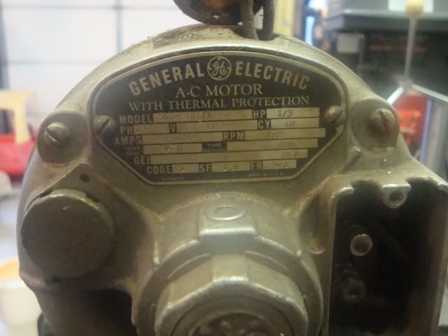
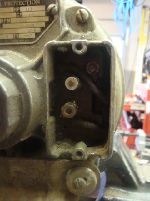
I have a 110v motor the plate is missing with the wiring diagram. I have a L1 L2 and possibly a L3 on the motor, and a 1 way switch that I have to mount. Now what... can someone out there give my brain a kick start.
Thank You
Paul Booth
 
Let's talk colors

110v motor(single speed only)

Black is Hot
White is Neutral
Green is ground

Twospeed motors
Black/Red Hot for Hi/Low
White Neutral
Green ground

If the motor is 110/220 dual wired things get slightly more complicated but still doable. What colors do you see?
 
Unfortunately no colors! The motor is an old GE model I don't believe the the terminal is L3 I can only make out L1 L2. Wiring the switch does not bother me its the motor. I just can't seem to find ground.
 
booth said:
Unfortunately no colors! The motor is an old GE model I don't believe the the terminal is L3 I can only make out L1 L2. Wiring the switch does not bother me its the motor. I just can't seem to find ground.


Usually there is no ground wire coming out of the motor. The ground you bring over with the circuit will be attached to the motor in the little juntion box called the "pecker head". What you might have there is a 3 phase motor. 3 phase motors will have a L1, L2, L3 leads. If you use an ohm meter like i previously described, and all 3 ways have about the same ohms, I am reasonably sure it would be 3 phase.
 
I agree with Steve. With L1, L2, L3 it sounds like a 3 phase motor.
 
Could still be a 110/220 volt motor. Especially if you are not sure there is an L3. The ohm meter check mentioned would let us know that.

What is really needed in this situation is a picture of what you see. Between you, me and the other very very knowledge people here, someone will be able to get you up and running.

But we really do need a picture of what you have and what you are looking at.
Any possiblity of that happening?
Kermit
 
Yes we could use a photo and the ohm readings also full nameplate data which will list phase voltage amps and usually a few other things. With this information there are several folks here that can solve the problem.

Dan
 
048.jpg

Hard to read 110v 1/3hp

049.jpg

Missing this plate

047.jpg

Used in this
 
OK
Going from the center post to bottom=1.4
center to top=1.5
top to bottom=it keeps changing I can't get an accurate reading.
 
Paul,
If you can read L1 and L2 the standard is that is Line 1 and Line 2 or the two legs of the 110 wire. It looks like there might be a ground screw in the top of the connection box.

If there is a resistance reading between L1 and L2 and an open circuit between both L1 to the frame and L2 to the frame then I am fairly certain that that you simply hook the white and black wire to the two terminals.

Also measure the third wire further in, if it is the ground connection it will read zero ohms to the frame. The ground wire needs to connect to the frame one of the cover screws could be used for a ground connection.

Dan
 
Thanks, I'll try that.

The lathe is an old Barnes 4 1/2. Treadle was taken off a long time ago. My 78 year old grandfather used this lathe when he was a boy. I'm just getting it back into shape...
Regards,
Paul
 
Yes the upper most, slightly out of line terminal is most likely the ground lug. The other two are Hot and Neutral.

Could use some cleaning, so you get a good metal to metal contact. Toothbrush and WD40? :big:

Suspect a blown fusible link if you hook it up and don't get any action. Notice the 'thermally protected' OEM printing. You would have to open the motor and find the link and replace or bypass it. It will be located 'on' the field coil to be responsive to overheating. looks like a tape wrapped lump in the wiring pigtail. Some units had them against the motor frame on the inside, may even have a screw and hold down plate over it.

wonderful that you have that piece of your grandfathers life in yours now.

Take care,
Kermit
 
I might as well throw in my guess along with all the others. The varying readings you get from the top terminal indicate that is one lead from the capacitor. The original instructions told you how to connect that lead to reverse the motor.

Since the motor came off the lathe then it will be connected for correct rotation so just connect your black and white wires to the L! and L2 terminals. Put a ring terminal on the end of the green wire (in your supply cord) and put it under the cover plate (which you are going to make) on the retaining screw. Alternately, you can drill a hole for a number 8 screw in the side of the junction box and use a screw, star washers l and a nut for the green wire.
 
the bottom one is live the middle one is neutral and the top one is an earth its non reversible its the same as the motor on my raglan little john the motor has the coveer but no label on the inside but thats how mine is wired up for forward (clockwise) running on the shaft my motor has been modified with 2 verry large capacitors to enable non biast to polarity meaning it can be run in reverse by wiring the live and neutral the other way
just my observations here fellas
regards john
 
Dan, I have to appologize. :-[ I miss read the introduction. I'll be more careful next time before I try to point something out.

Paul, that is one nice machine! ;D
 
Thanks guys, I'll try that tonight. It's to darn hot in the shop right now.
 

Latest posts

Back
Top