
You are using an out of date browser. It may not display this or other websites correctly.
You should upgrade or use an alternative browser.
You should upgrade or use an alternative browser.
Double-Cross. Elmer's #34 Cross Twin Engine
- Thread starter Sshire
- Start date


Help Support Home Model Engine Machinist Forum:
This site may earn a commission from merchant affiliate
links, including eBay, Amazon, and others.
Sshire
Well-Known Member
- Joined
- Jun 29, 2011
- Messages
- 936
- Reaction score
- 259
Double-Cross
Elmers #34 - Cross Twin Engine
Part 9
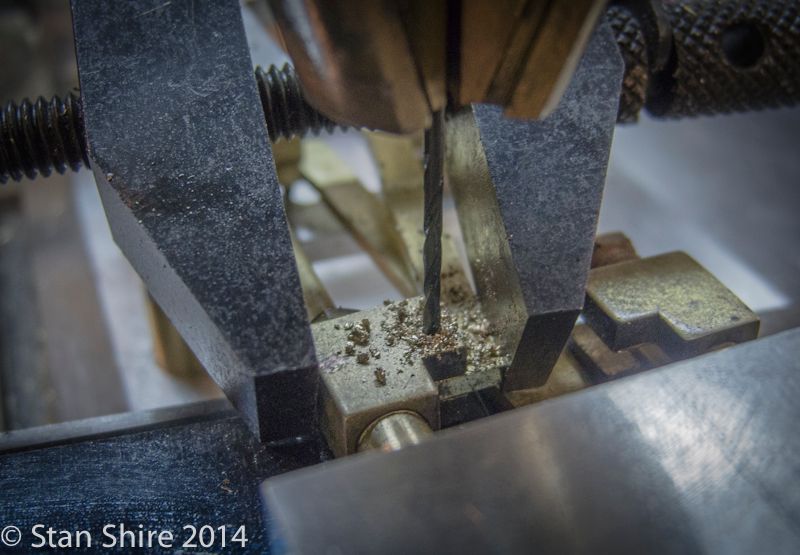
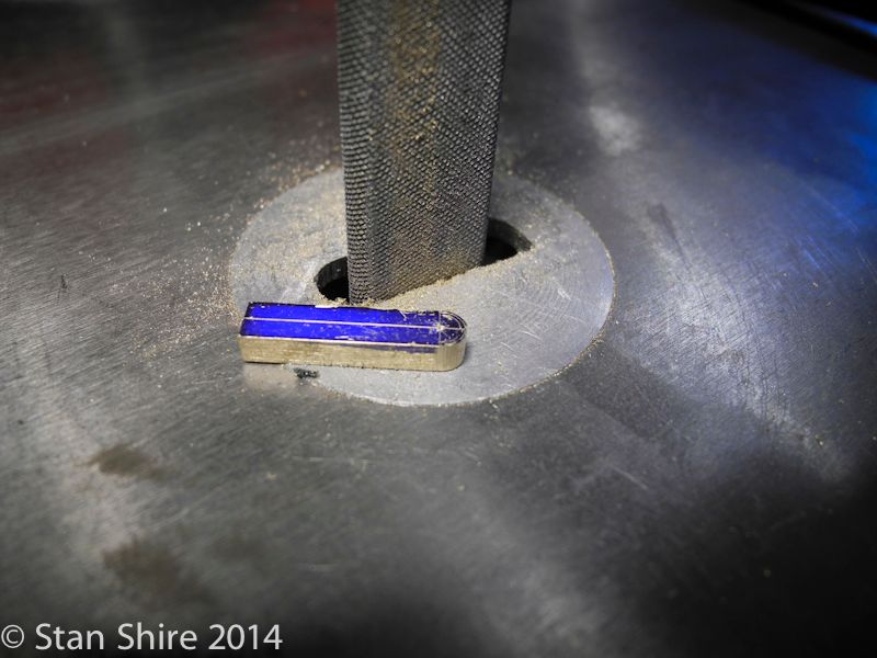
I cut the oil grooves in the piston [.015"x.008"] and then spot drilled.
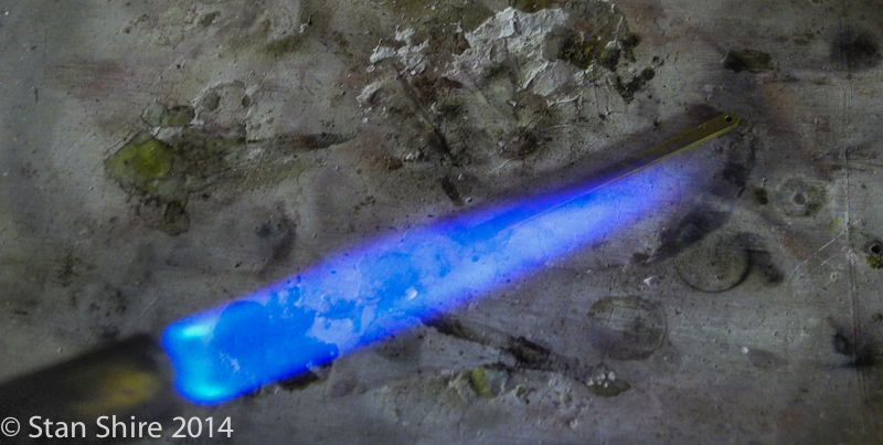
Elmer has the piston rods silver brazed in the piston. I set up the parts and soon after the torch hit the 3/32 rod, it bent to one side. The torch was not that hot.
I love making parts twice. The piston was a 10 minute job so no major loss. Heres Plan B.
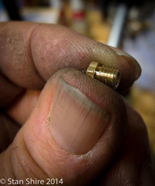
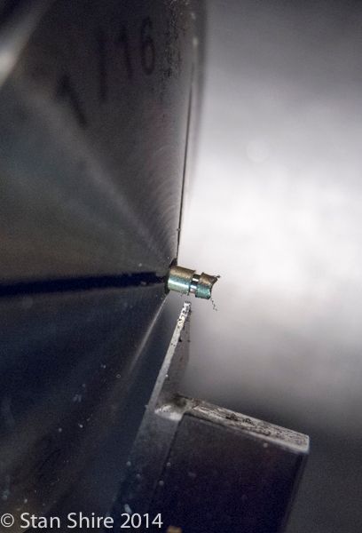
The short rod is threaded for the stuffing box. Test fit here.
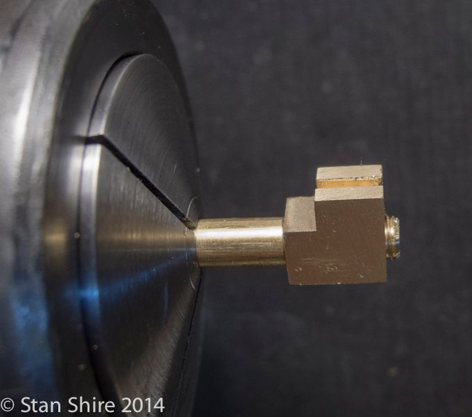
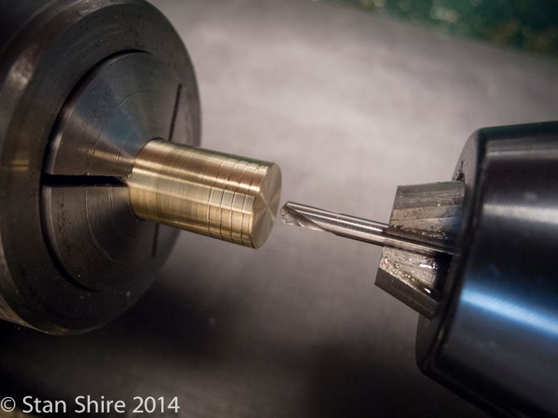
Then drilled for the 3/32 rod to slide through.
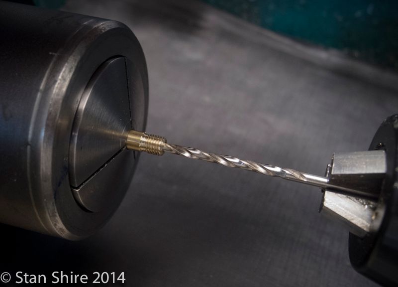
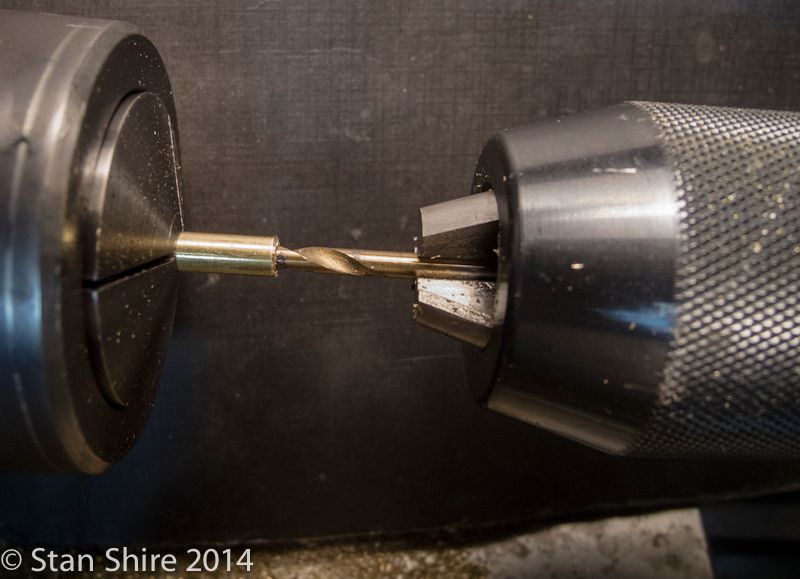
The rod is flipped, end for end, and drilled .125
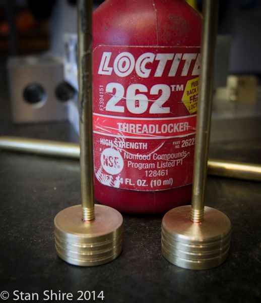
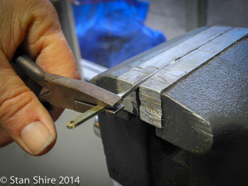
Ready for Loctite 609. Parts cleaned in acetone and then Loctite primer painted on.
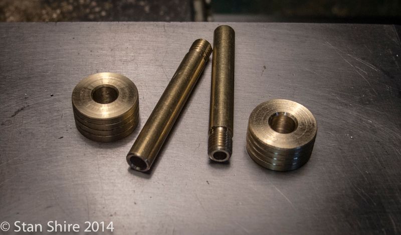
Waiting until tomorrow for the Loctite to cure.
Looks like the crossheads are on the schedule for tomorrow.
Stay tuned.
Elmers #34 - Cross Twin Engine
Part 9
I cut the oil grooves in the piston [.015"x.008"] and then spot drilled.

Elmer has the piston rods silver brazed in the piston. I set up the parts and soon after the torch hit the 3/32 rod, it bent to one side. The torch was not that hot.

I love making parts twice. The piston was a 10 minute job so no major loss. Heres Plan B.


The short rod is threaded for the stuffing box. Test fit here.

Then drilled for the 3/32 rod to slide through.

The rod is flipped, end for end, and drilled .125

Ready for Loctite 609. Parts cleaned in acetone and then Loctite primer painted on.

Waiting until tomorrow for the Loctite to cure.

Looks like the crossheads are on the schedule for tomorrow.
Stay tuned.
vascon2196
Well-Known Member
- Joined
- Oct 2, 2009
- Messages
- 1,026
- Reaction score
- 312
Great job Stan...keep her going.
Sshire
Well-Known Member
- Joined
- Jun 29, 2011
- Messages
- 936
- Reaction score
- 259
Double-Cross
Elmers #34 - Cross Twin Engine
Part 10
Crossheads
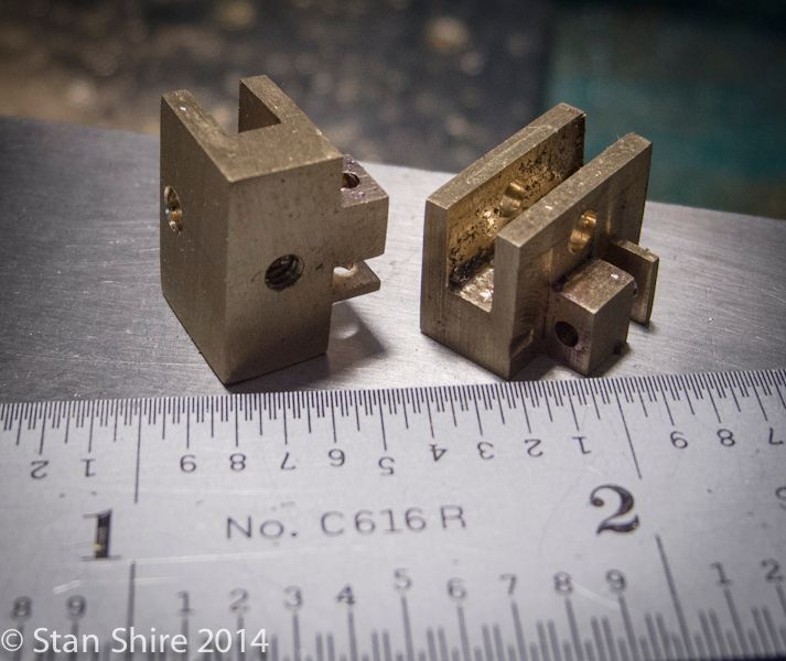
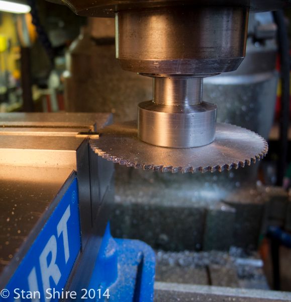
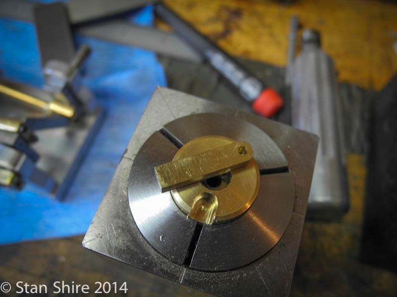
I machined both crossheads on one piece of brass and then cut each to length. I started with enough material to make three crossheads (just in case)
Elmer has a four step procedure which eliminates the which cut do I do first so Im not backed into a corner issue. The first two are done without moving the part
And after those cuts, we have this.
Then the part is flipped in the vise to machine the cross cuts. The slot will accept the crosshead link.

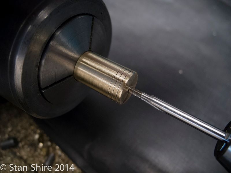
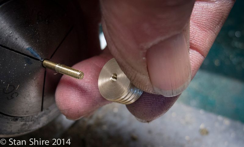
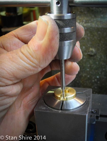
Then another turn for drilling and tapping for the piston rod.
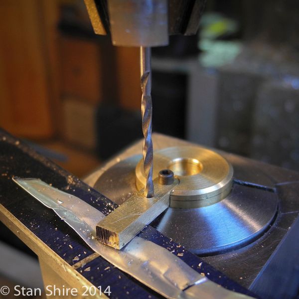
Now, with the crossheads separated, the part is turned again for another hole . This one is for the 1/16 retaining pin for the crosshead link.
In standard Elmer design, the pin gets a #70 hole cross drilled to accept a piece of wire to keep the pin in position. Ive never liked this method of retaining pins. A few engines ago, I discovered 1/16 e-clips and a neat tool to snap them onto a .053 O.D. groove on the 1/16 shaft. When I make the pins, Ill be sure to show that tool again. Its used by RC airplane and car people.
Two crossheads, hot off the mill.
I had left the pistons a few thou large and this seemed like a good time to fit them. Various grits of paper and some Scotchbrite with many test fits.
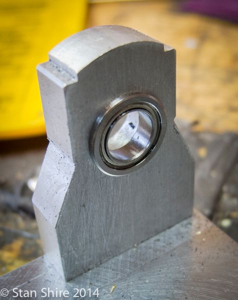
With the pistons fitted, I needed to Loctite the bearings into the housings. The people that I spoke with at Boca Bearings said finger press fit. I also had the same advice from some folks at MEM when I built the RV-2. (I believe they speak from experience about tight fits on these bearings)
Originally, I had the bearings on the inside of the housings but didnt like the big, empty clearance hole on the outside. So, those were relocated to the outer face. Loctite 609.
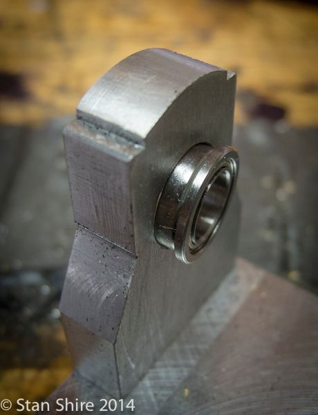
Finger press and
I now had enough parts made to do a trial assembly to find any places that needed attention. I had lots of binding. I just love following the builds which go So I machined the 834 parts, put it together and it runs on 2 PSI. A bit of running-in should get that down to running on a light breeze.
OK. That NEVER happened on any of my builds, but after some fettling, sanding, more fettling, more fettling, more fettling, I can turn the crankshaft with my fingers and its all moving with nary a bind.
Im quite sure that as I add the rest of the parts, Ill have some issues but at least I know that its not the pistons, rods, crossheads, crankshaft, bearings or con rods.
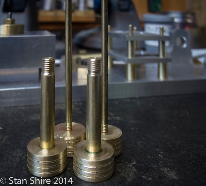
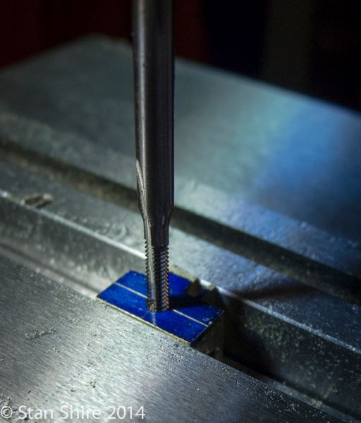
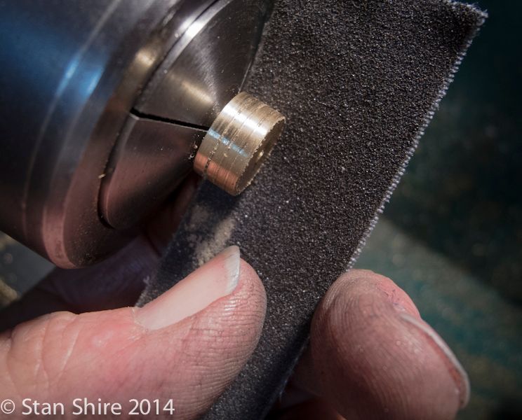
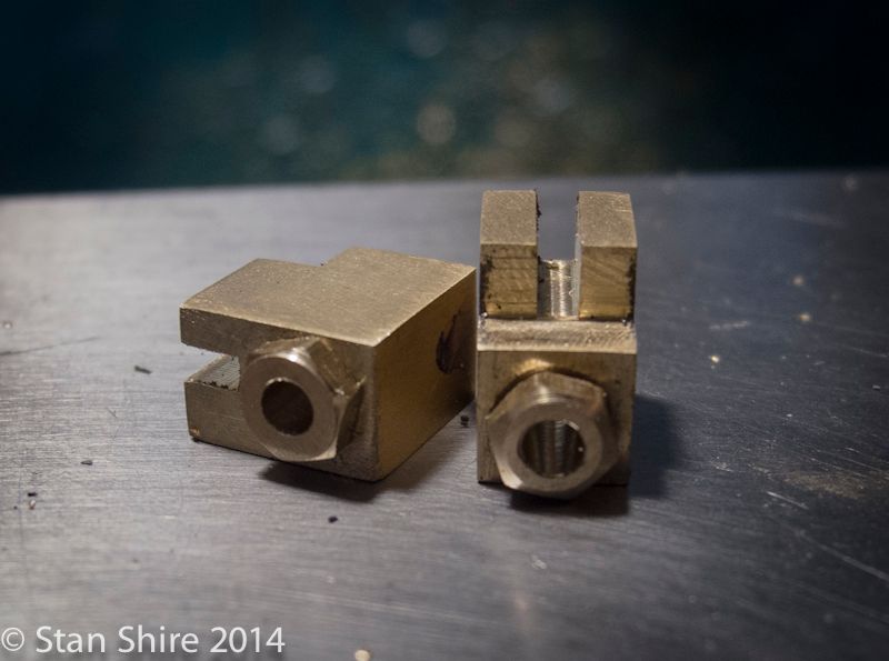
A pair of pack nuts for the stuffing box.

I really should have just taken a picture of my fingers yesterday when they were squeaky-clean.
Installed in the stuffing boxes.
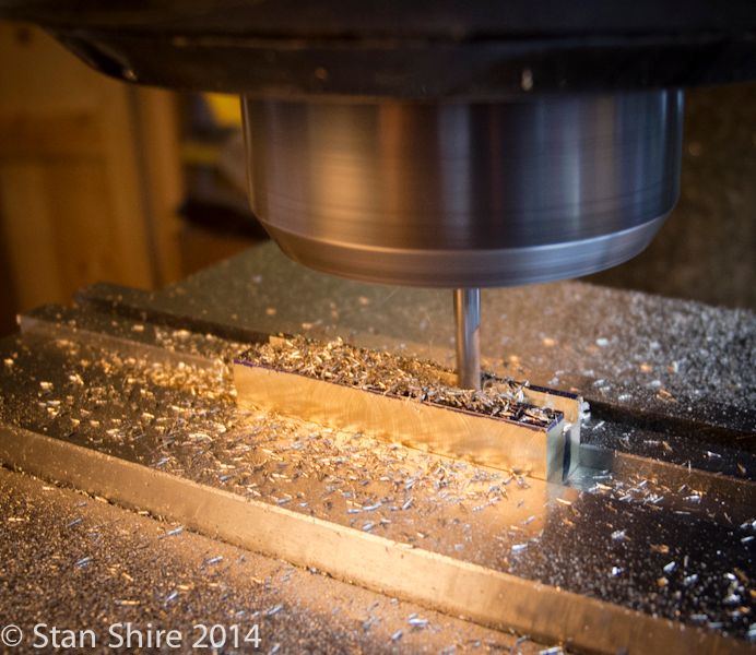
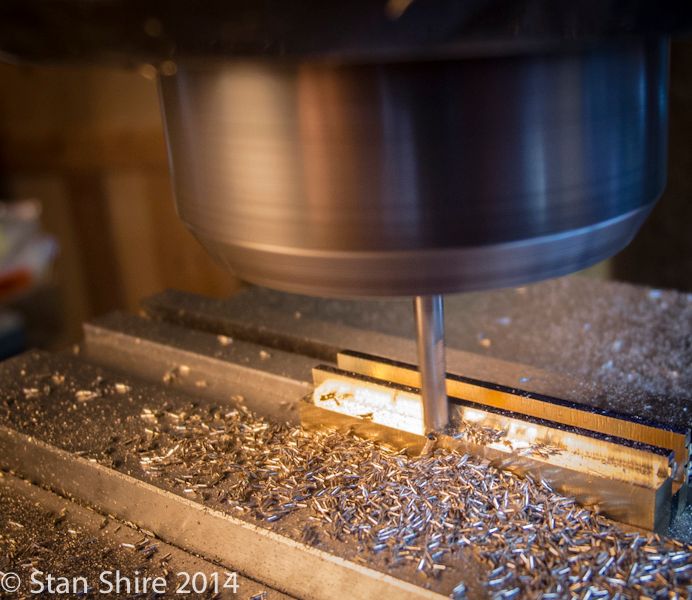
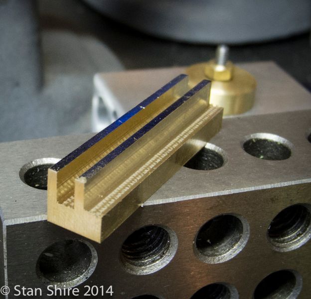
Now onto the crosshead links. I laid them out on 1/16 brass sheet, rough cut on the bandsaw, on finished by milling to the line.
Then a 1/16 hole in each for the retaining pin.
Then they are silver brazed into the slot on the stuffing box.
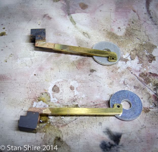
More polishing to do, but these are done.
Thanks for pulling up a chair.
Elmers #34 - Cross Twin Engine
Part 10
Crossheads
I machined both crossheads on one piece of brass and then cut each to length. I started with enough material to make three crossheads (just in case)
Elmer has a four step procedure which eliminates the which cut do I do first so Im not backed into a corner issue. The first two are done without moving the part


And after those cuts, we have this.

Then the part is flipped in the vise to machine the cross cuts. The slot will accept the crosshead link.

Then another turn for drilling and tapping for the piston rod.

Now, with the crossheads separated, the part is turned again for another hole . This one is for the 1/16 retaining pin for the crosshead link.
In standard Elmer design, the pin gets a #70 hole cross drilled to accept a piece of wire to keep the pin in position. Ive never liked this method of retaining pins. A few engines ago, I discovered 1/16 e-clips and a neat tool to snap them onto a .053 O.D. groove on the 1/16 shaft. When I make the pins, Ill be sure to show that tool again. Its used by RC airplane and car people.

Two crossheads, hot off the mill.

I had left the pistons a few thou large and this seemed like a good time to fit them. Various grits of paper and some Scotchbrite with many test fits.

With the pistons fitted, I needed to Loctite the bearings into the housings. The people that I spoke with at Boca Bearings said finger press fit. I also had the same advice from some folks at MEM when I built the RV-2. (I believe they speak from experience about tight fits on these bearings)
Originally, I had the bearings on the inside of the housings but didnt like the big, empty clearance hole on the outside. So, those were relocated to the outer face. Loctite 609.

Finger press and

I now had enough parts made to do a trial assembly to find any places that needed attention. I had lots of binding. I just love following the builds which go So I machined the 834 parts, put it together and it runs on 2 PSI. A bit of running-in should get that down to running on a light breeze.
OK. That NEVER happened on any of my builds, but after some fettling, sanding, more fettling, more fettling, more fettling, I can turn the crankshaft with my fingers and its all moving with nary a bind.
Im quite sure that as I add the rest of the parts, Ill have some issues but at least I know that its not the pistons, rods, crossheads, crankshaft, bearings or con rods.

A pair of pack nuts for the stuffing box.


I really should have just taken a picture of my fingers yesterday when they were squeaky-clean.
Installed in the stuffing boxes.

Now onto the crosshead links. I laid them out on 1/16 brass sheet, rough cut on the bandsaw, on finished by milling to the line.

Then a 1/16 hole in each for the retaining pin.

Then they are silver brazed into the slot on the stuffing box.

More polishing to do, but these are done.

Thanks for pulling up a chair.
Sshire
Well-Known Member
- Joined
- Jun 29, 2011
- Messages
- 936
- Reaction score
- 259
Double-Cross
Elmers #34 - Cross Twin Engine
Part 11
Getting near the end of the line. Except for one little glitch.
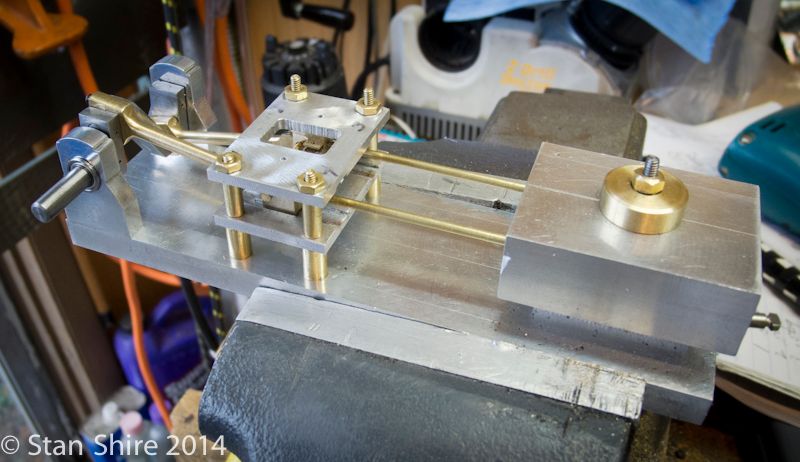
I had been running the engine (powered by the Bridgeport) with Timesaver in the cylinders to smooth out a slight bind. After about 10 minutes, it was turning by finger power smooth as silk. Binding gone.
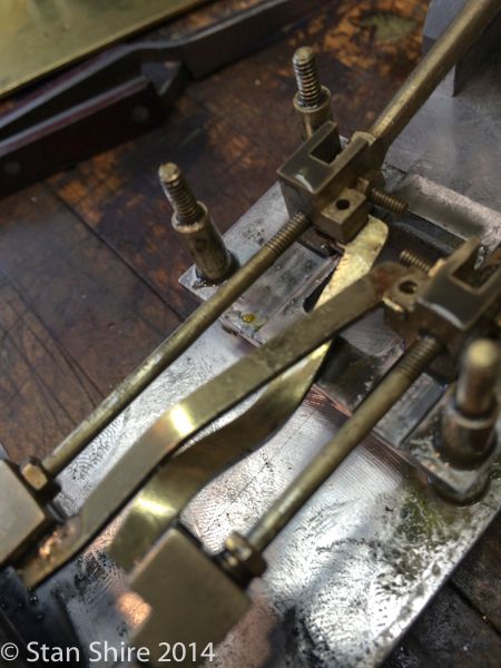
I figured since that went so well, Id install the crosshead links and run it in a bit more on the mill.
Links installed, I hand turned the crankshaft about a half turn forward and a half turn back. Felt good.
Note to self. Turn the damn crank a full turn to check.
The VFD on the Bridgeport was set very slow.
Question: What happens when you make the links from a 2 wide piece of brass and layout the crosshead links perfectly except you forget to mill the 2 long piece to the correct (shorter) dimension?
Answer: This is what happens.
They did end up at precisely the correct length after the Bridgeports correction.
I was able to unsolder the links from the stuffing boxes and remade the links. This time at the correct length. I also decided to bag the soldering and fix then to the stuffing boxes with 0-80 screws. These will be replaced with 0-=80 hex head brass screws when they arrive from Microfasteners.
So, the new links were attached to the crossheads and I clamped the other end in position and drilled, tapped and made a clearance hole 0-80.
The new links were fixed in place and I tested the movement with a number of full revolutions of the crank.
[ame]http://www.youtube.com/watch?v=gxKml5m2gIs[/ame]
I had mentioned that I was less than happy with Elmers retaining parts on shafts with a hole and wire. If you missed the magic E-clip tool in one of my past builds, heres a rerun from this engine.
The 1/16 shaft is grooved to .052. Im using a Warner grooving tool although Ive heard good things about the Kaiser Thinbit tooling.
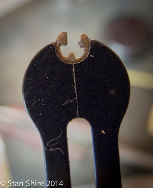
Heres the 1/16 E-clip.

This is the tool. Although its metric, the imperial clips work just fine. I got it from one of the model RC airplane/car sites. Seems to be a pretty standard item.
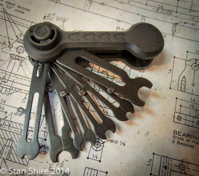
My technique is to grab the clip with tweezers and push it into the tool.
And you just push it into the groove. To remove a clip, you push the tool against the clips open end.
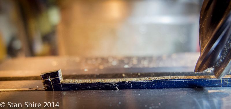
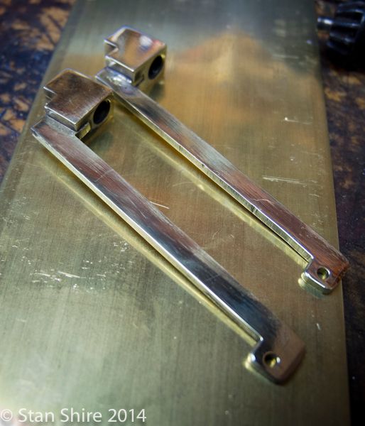
With the grooves and clips done, I moved onto the other two links. Rough cut on the bandsaw and milled to the line.
The link ends were rounded at Oliver. and then drilled.
The link from the crankshaft to the crank is 1/16 thick soldered into a ⅛ built-up end. Using a .062 slitting saw to cut the ⅛ end piece.
So, the valve linkage tomorrow and a temporary flywheel, and hopefully, a first run on air.
Just to hold you over, heres a run-in with the new cross links.
[ame]http://www.youtube.com/watch?v=wsDF4q39ijs[/ame]
Elmers #34 - Cross Twin Engine
Part 11
Getting near the end of the line. Except for one little glitch.
I had been running the engine (powered by the Bridgeport) with Timesaver in the cylinders to smooth out a slight bind. After about 10 minutes, it was turning by finger power smooth as silk. Binding gone.
I figured since that went so well, Id install the crosshead links and run it in a bit more on the mill.
Links installed, I hand turned the crankshaft about a half turn forward and a half turn back. Felt good.
Note to self. Turn the damn crank a full turn to check.
The VFD on the Bridgeport was set very slow.
Question: What happens when you make the links from a 2 wide piece of brass and layout the crosshead links perfectly except you forget to mill the 2 long piece to the correct (shorter) dimension?
Answer: This is what happens.

They did end up at precisely the correct length after the Bridgeports correction.
I was able to unsolder the links from the stuffing boxes and remade the links. This time at the correct length. I also decided to bag the soldering and fix then to the stuffing boxes with 0-80 screws. These will be replaced with 0-=80 hex head brass screws when they arrive from Microfasteners.
So, the new links were attached to the crossheads and I clamped the other end in position and drilled, tapped and made a clearance hole 0-80.


The new links were fixed in place and I tested the movement with a number of full revolutions of the crank.
[ame]http://www.youtube.com/watch?v=gxKml5m2gIs[/ame]
I had mentioned that I was less than happy with Elmers retaining parts on shafts with a hole and wire. If you missed the magic E-clip tool in one of my past builds, heres a rerun from this engine.
The 1/16 shaft is grooved to .052. Im using a Warner grooving tool although Ive heard good things about the Kaiser Thinbit tooling.

Heres the 1/16 E-clip.

This is the tool. Although its metric, the imperial clips work just fine. I got it from one of the model RC airplane/car sites. Seems to be a pretty standard item.

My technique is to grab the clip with tweezers and push it into the tool.

And you just push it into the groove. To remove a clip, you push the tool against the clips open end.

With the grooves and clips done, I moved onto the other two links. Rough cut on the bandsaw and milled to the line.

The link ends were rounded at Oliver. and then drilled.


The link from the crankshaft to the crank is 1/16 thick soldered into a ⅛ built-up end. Using a .062 slitting saw to cut the ⅛ end piece.

So, the valve linkage tomorrow and a temporary flywheel, and hopefully, a first run on air.
Just to hold you over, heres a run-in with the new cross links.
[ame]http://www.youtube.com/watch?v=wsDF4q39ijs[/ame]
Walltoddj
Well-Known Member
- Joined
- Aug 5, 2013
- Messages
- 145
- Reaction score
- 57
I like your little E-clip pliers they look very handy, I loose a lot of them because they try to fly off. Nice job on the engine it looks great!!
Ps. I'll have to see when GM has another open house they just did a 75th last fall.
Todd
Ps. I'll have to see when GM has another open house they just did a 75th last fall.
Todd
Sshire
Well-Known Member
- Joined
- Jun 29, 2011
- Messages
- 936
- Reaction score
- 259
Thanks for the kind words. 2 ½ years ago, I hadn't ever seen a metal lathe, didn't know 6061 from Reynolds Wrap and thought coolant was something the HVAC guy put in my central A/C if it was too hot.
It is consuming and I love it.
It is consuming and I love it.
Sshire
Well-Known Member
- Joined
- Jun 29, 2011
- Messages
- 936
- Reaction score
- 259
Double-Cross
Elmers #34 - Cross Twin Engine
Part 12
The link that connects to the valve has a 90 degree twist. It seemed like a good idea to anneal the link before bending.
and the twist went without incident (amazing in itself)
Now, a tricky part and a story.
My son sent me this for my birthday last August.
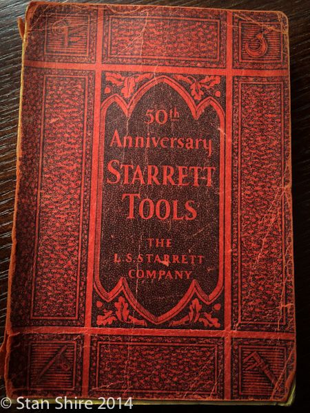
In it, I saw these. I had never seen (nor heard of) Key Seat clamps, but after reading the old catalog, I went to Starretts website to see if theyre still made because it seemed like they could be useful for something.
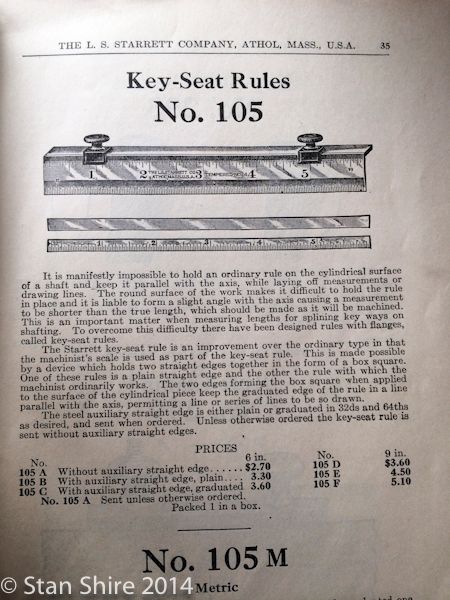
So, there they were, although the price has gone up a bit. $134.00 the pair!
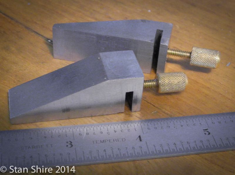
Hell, I thought, I can make those. I couldnt get a real sense of the size from the catalog (and paid no attention to the size which was clearly on the Starrett website.)
So, here they are.
But wait, theres more to the story.
I was on a recent aluminum buying excursion to Fazzios in the wilds of New Jersey, In addition to the supermarket-like aluminum and stainless building, Fazzios has a secret building with the most amazing collection of used stuff from machine, welding and fab shops. Need a 4 end mill or a circa 1960 stick welder? Thats the place. Its a rabbit warren of room after room of absolutely neat stuff.
Now, imagine this block-long building, marginally lit, filled 20 feet high with shelf after shelf of stuff.
I was quickly passing an aisle of vises when my Starrett Detector went to full alert. I carefully looked at the shelves in front of me and something was calling my name. Stuffed between 20 beaten-to-death Bridgeport vises was this tiny box.
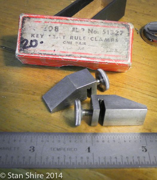
Of course, they came home with me and went into the toolbox.
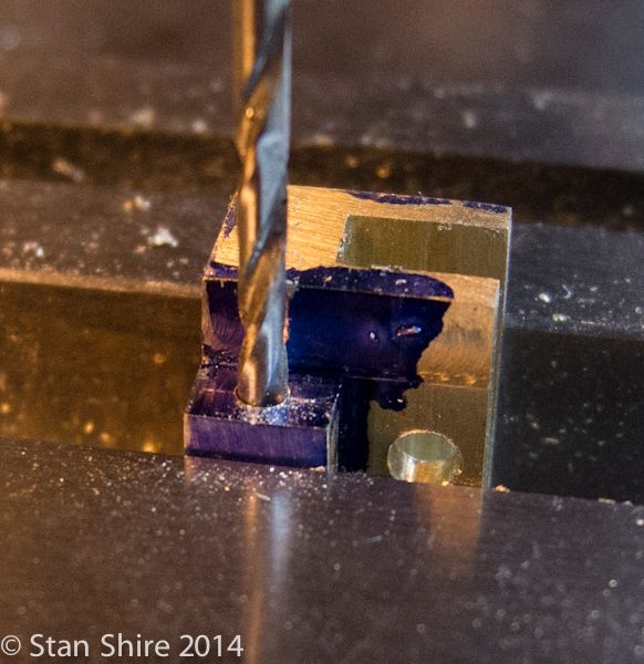
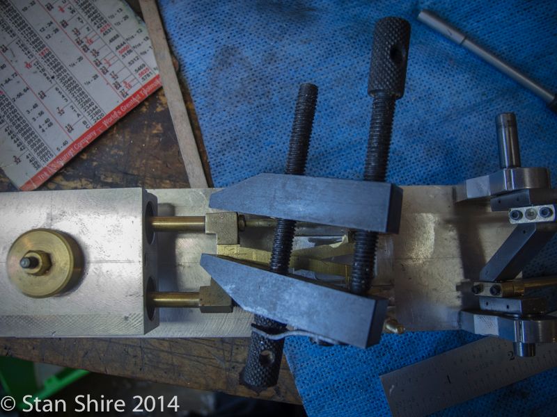
So, now Im trying to figure out how to transfer a line from the bottom of the valve to cut an aligned slot on the top of the valve for the 90 degree twisted link.
KEY SEAT CLAMPS!!!
First scribing a line with the center head to bisect two ports.
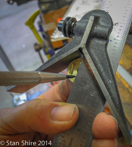
Then the key seat clamps to scribe a parallel line down to edge.
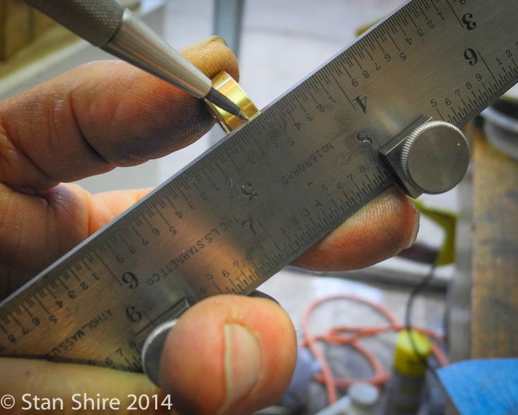
My friend, Fred, who got me into this stuff, suggested the parallels to get the centerline closer to the edge of the ruler.
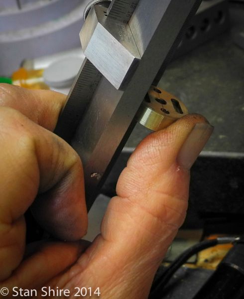
With the scribe line perpendicular to the face of the collet block
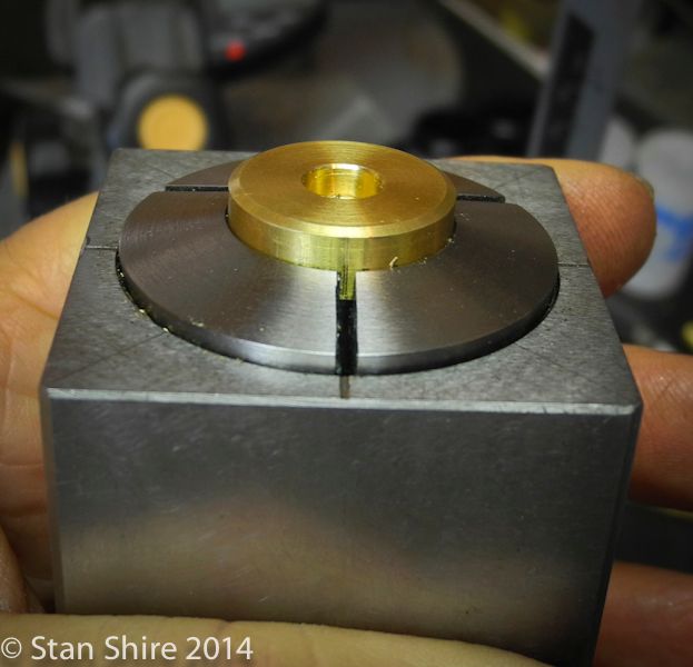
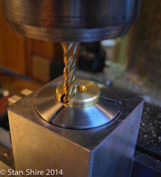
the slot was easily cut.
The valve crank (which goes into the slot) was rounded over at Oliver.
The plans call for silver brazing this piece into the slot. I really wanted to leave my options open because if there was binding, I was going with Gails ball joints. I decided to insert the crank with a 1-72 screw and then, if all is well, Ill either replace the SHCS with a brass hex head bolt or silver braze it in.
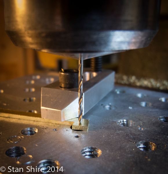
So, a 1-72 clearance hole and a tiny, shop-made 1-72 transfer punch (wire brad).
Then, a 1-72 tap, turned with thumb and finger.

Now a 1/16 hole for the crank pin, .50 from the valve center.
I found an aluminum plug in the scrap box for a temporary flywheel, so theres nothing for it but to plug in some air.
[ame]http://www.youtube.com/watch?v=D1bboqTd3lM[/ame]
ITS A RUNNER!!!
Now I have to take it apart for some finish machining and polishing.
Elmers #34 - Cross Twin Engine
Part 12
The link that connects to the valve has a 90 degree twist. It seemed like a good idea to anneal the link before bending.

and the twist went without incident (amazing in itself)

Now, a tricky part and a story.
My son sent me this for my birthday last August.

In it, I saw these. I had never seen (nor heard of) Key Seat clamps, but after reading the old catalog, I went to Starretts website to see if theyre still made because it seemed like they could be useful for something.

So, there they were, although the price has gone up a bit. $134.00 the pair!
Hell, I thought, I can make those. I couldnt get a real sense of the size from the catalog (and paid no attention to the size which was clearly on the Starrett website.)
So, here they are.

But wait, theres more to the story.
I was on a recent aluminum buying excursion to Fazzios in the wilds of New Jersey, In addition to the supermarket-like aluminum and stainless building, Fazzios has a secret building with the most amazing collection of used stuff from machine, welding and fab shops. Need a 4 end mill or a circa 1960 stick welder? Thats the place. Its a rabbit warren of room after room of absolutely neat stuff.
Now, imagine this block-long building, marginally lit, filled 20 feet high with shelf after shelf of stuff.
I was quickly passing an aisle of vises when my Starrett Detector went to full alert. I carefully looked at the shelves in front of me and something was calling my name. Stuffed between 20 beaten-to-death Bridgeport vises was this tiny box.

Of course, they came home with me and went into the toolbox.
So, now Im trying to figure out how to transfer a line from the bottom of the valve to cut an aligned slot on the top of the valve for the 90 degree twisted link.
KEY SEAT CLAMPS!!!
First scribing a line with the center head to bisect two ports.

Then the key seat clamps to scribe a parallel line down to edge.

My friend, Fred, who got me into this stuff, suggested the parallels to get the centerline closer to the edge of the ruler.

With the scribe line perpendicular to the face of the collet block

the slot was easily cut.

The valve crank (which goes into the slot) was rounded over at Oliver.

The plans call for silver brazing this piece into the slot. I really wanted to leave my options open because if there was binding, I was going with Gails ball joints. I decided to insert the crank with a 1-72 screw and then, if all is well, Ill either replace the SHCS with a brass hex head bolt or silver braze it in.
So, a 1-72 clearance hole and a tiny, shop-made 1-72 transfer punch (wire brad).

Then, a 1-72 tap, turned with thumb and finger.


Now a 1/16 hole for the crank pin, .50 from the valve center.

I found an aluminum plug in the scrap box for a temporary flywheel, so theres nothing for it but to plug in some air.
[ame]http://www.youtube.com/watch?v=D1bboqTd3lM[/ame]
ITS A RUNNER!!!
Now I have to take it apart for some finish machining and polishing.
vascon2196
Well-Known Member
- Joined
- Oct 2, 2009
- Messages
- 1,026
- Reaction score
- 312
Another great Elmer's engine...awesome job Stan!
vascon2196
Well-Known Member
- Joined
- Oct 2, 2009
- Messages
- 1,026
- Reaction score
- 312
I would love to attend the show again...I have to take another look at the dates to see if I can. I drove down there by myself a few years back and it was amazing to see how many people in this hobby under one roof.
I know your going...its right in your backyard isn't it?
We'll see...
I know your going...its right in your backyard isn't it?
We'll see...
Sshire
Well-Known Member
- Joined
- Jun 29, 2011
- Messages
- 936
- Reaction score
- 259
Double-Cross
Elmers #34 - Cross Twin Engine
Part 13
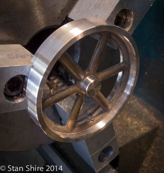
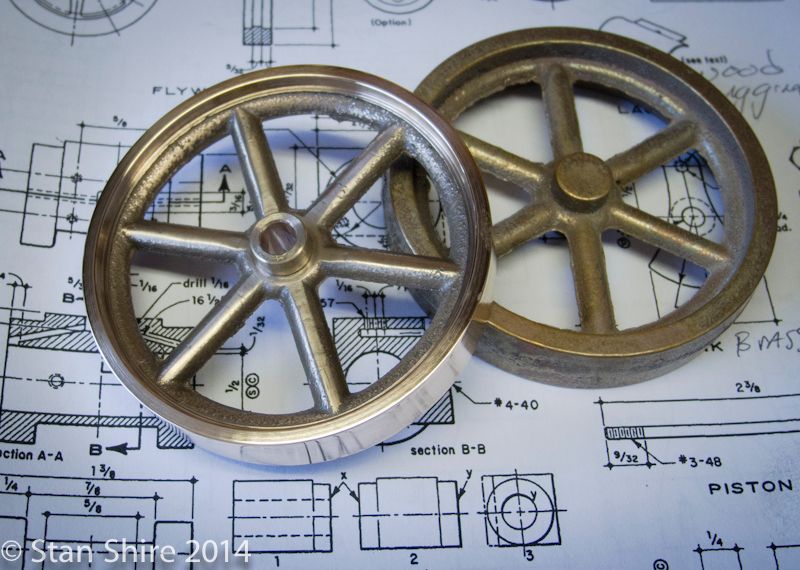
I was thinking that this engine was done. The cast iron flywheel (solid, with recessed center and drilled through with 5 holes) just looked wrong. Two things were bothering me. First, it looked too small (made to Elmers plans) and second, I felt that a heavier flywheel would allow the engine to run a bit slower.
After checking the engine for clearance, it seemed that a spoked, 3 flywheel would be a better choice. I do have a 3 round bar of C.I. and Marvs flywheel program does the spokes dead on. Then, I remembered how nice the PM Research cast flywheels were when I saw them at Cabin Fever last year. Ordered 2, 3 bronze, spoked, 7.5 oz flywheels on Monday and Richie, my UPS guy dropped them off on Wednesday. Id never machined a flywheel casting (or any casting) but, what the hell.
Mounted the three-jaw and bolted a set of home-brew soft jaws. I preloaded the jaws and bored a 0.25 deep recess and mounted the casting.
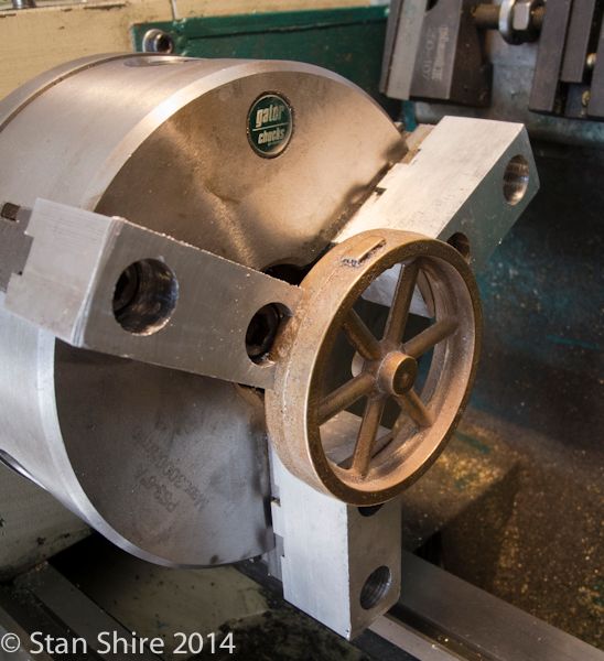
I was able to face the rim and hub and then turn the hubs O.D. Did a bit more than half of the rim O.D.
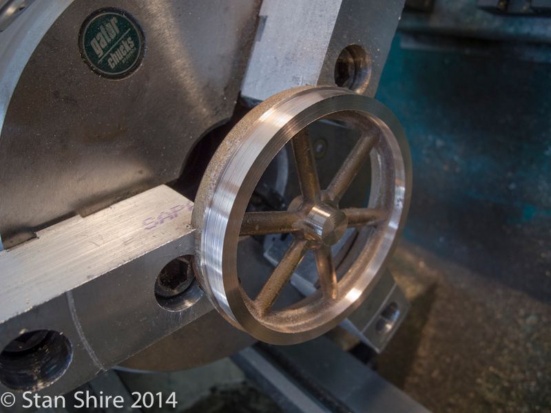
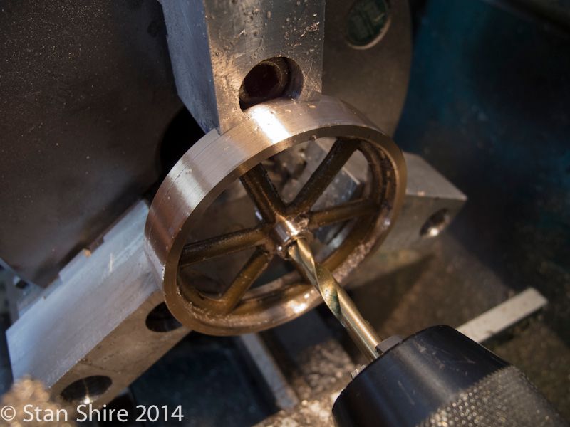
Then flipped around and repeat on the other side.
It was easier to see what was happening by cutting the inside of the rim from the rear with the lathe running in reverse.
Good so far.
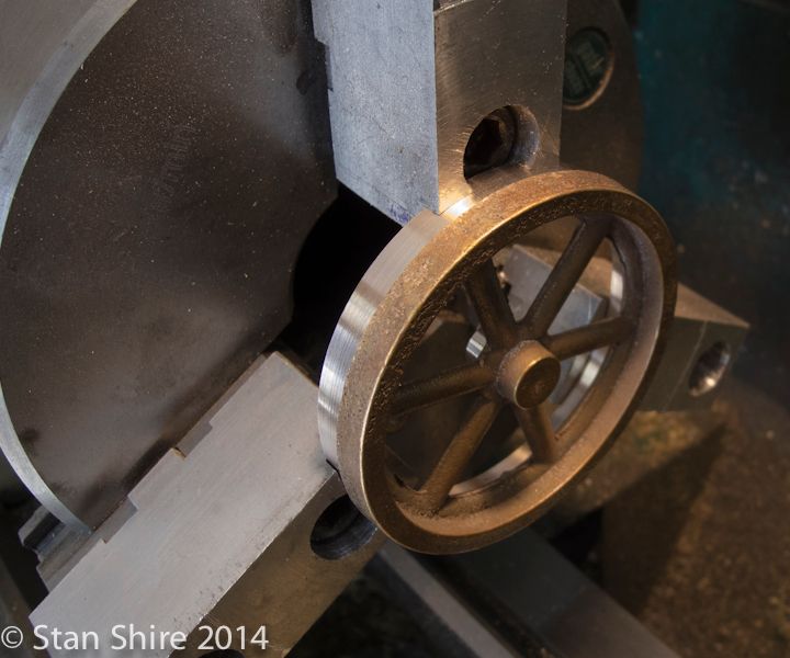
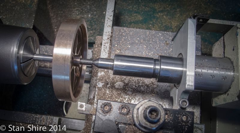
Drilling and reaming for the shaft.
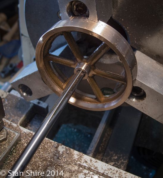
I pressed a tapered mandrel into the hole and went back to the 5C and the thin live center.
There was some wobble, but a bit of facing and turning had it running wobble-free.
I had ordered two flywheels figuring that I might screw one up, but it was less stressful than I thought.
Now, Ive got one for the next engine.
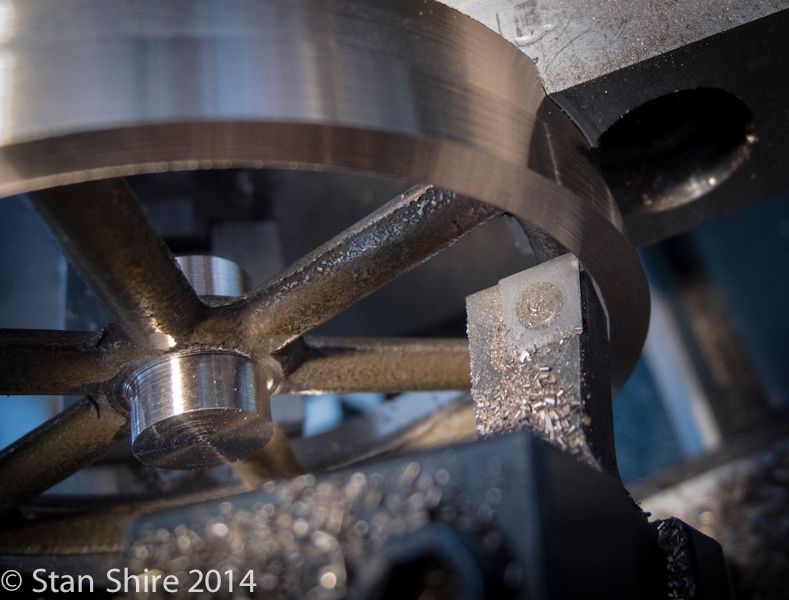
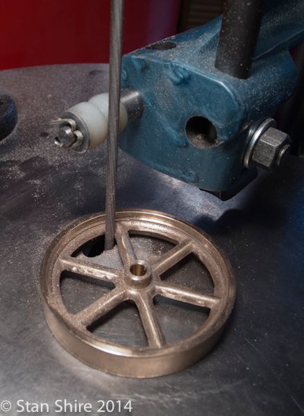
Oliver made short work of removing the flash, then 1 rolls of abrasive, small files, and about an hour finished the spokes.
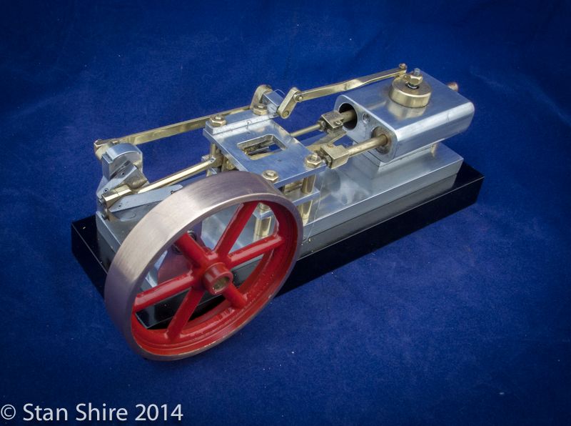
Self-etching primer (2 coats) and paint (3 coats) and Im definitely calling this one done.
Thanks for following along.

Since I have that extra flywheel, watch for this build in the next few days.
Elmers #34 - Cross Twin Engine
Part 13
I was thinking that this engine was done. The cast iron flywheel (solid, with recessed center and drilled through with 5 holes) just looked wrong. Two things were bothering me. First, it looked too small (made to Elmers plans) and second, I felt that a heavier flywheel would allow the engine to run a bit slower.
After checking the engine for clearance, it seemed that a spoked, 3 flywheel would be a better choice. I do have a 3 round bar of C.I. and Marvs flywheel program does the spokes dead on. Then, I remembered how nice the PM Research cast flywheels were when I saw them at Cabin Fever last year. Ordered 2, 3 bronze, spoked, 7.5 oz flywheels on Monday and Richie, my UPS guy dropped them off on Wednesday. Id never machined a flywheel casting (or any casting) but, what the hell.
Mounted the three-jaw and bolted a set of home-brew soft jaws. I preloaded the jaws and bored a 0.25 deep recess and mounted the casting.

I was able to face the rim and hub and then turn the hubs O.D. Did a bit more than half of the rim O.D.

Then flipped around and repeat on the other side.

It was easier to see what was happening by cutting the inside of the rim from the rear with the lathe running in reverse.

Good so far.

Drilling and reaming for the shaft.


I pressed a tapered mandrel into the hole and went back to the 5C and the thin live center.
There was some wobble, but a bit of facing and turning had it running wobble-free.

I had ordered two flywheels figuring that I might screw one up, but it was less stressful than I thought.
Now, Ive got one for the next engine.

Oliver made short work of removing the flash, then 1 rolls of abrasive, small files, and about an hour finished the spokes.

Self-etching primer (2 coats) and paint (3 coats) and Im definitely calling this one done.
Thanks for following along.


Since I have that extra flywheel, watch for this build in the next few days.

- Joined
- Mar 9, 2010
- Messages
- 597
- Reaction score
- 704
Nice work on the flywheel - the one picture where you are filing the spokes though - what kind of machine is that? Is it a jig saw with a file mounted somehow?
You called it Oliver - must be a favorite tool....
You called it Oliver - must be a favorite tool....
Sshire
Well-Known Member
- Joined
- Jun 29, 2011
- Messages
- 936
- Reaction score
- 259
Thanks, Crueby
Oliver is a 1970 Oliver of Adrian (Michigan) S-4 Die Filer.
Some info here but unlike these pictures, mine has the optional 16" table, the roller and spring- loaded file support and looks like brand new.
http://vintagemachinery.org/photoindex/detail.aspx?id=12190
Here's mine
Oliver is a 1970 Oliver of Adrian (Michigan) S-4 Die Filer.
Some info here but unlike these pictures, mine has the optional 16" table, the roller and spring- loaded file support and looks like brand new.
http://vintagemachinery.org/photoindex/detail.aspx?id=12190
Here's mine

Last edited:
Similar threads
- Replies
- 31
- Views
- 3K
- Replies
- 1
- Views
- 1K