


Sshire
Well-Known Member
- Joined
- Jun 29, 2011
- Messages
- 936
- Reaction score
- 259
Double-Cross
Elmers #34 - Cross Twin Engine
Part 1
Other than polishing, the Liney RV-2 is done. So, here we go with the next engine.
Ive always wanted to do a horizontal engine and Elmers #34 - Cross Twin Engine seemed intriguing.
After reading the drawings, so that I understand how the engine works, I called my neighbor, Fred, who has a virgin copy of the actual Elmers Engine book. The John-Tom drawings are fine but the pictures look like the result of someone who has a $3.00 scanner and has no idea how to use it. As far as I could tell, the picture was either an engine or a Koala in heat. Having the book, with Elmers very clear pictures, is a major help.
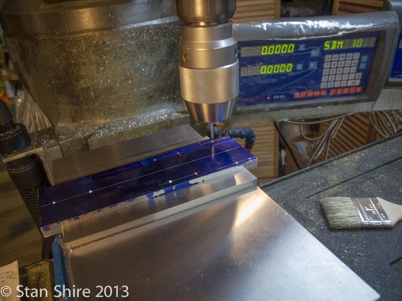
I started with the base. 6061 aluminum plate. My normal procedure is to mark the piece as a sanity check with the DRO.
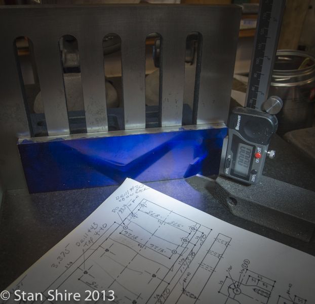
After cutting a rough-size piece, squaring and sizing it from the 3/8 6061 plate, spot drilling, drilling and tapping commenced.
All holes were put in as SDM (sub data memory) in the DRO. This way I can do all spot drilling, then all drilling, then all tapping just by going to the 10 sub-data points.
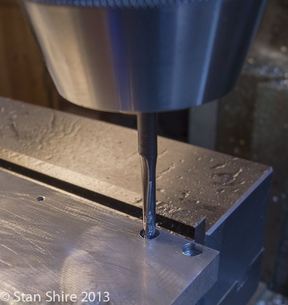
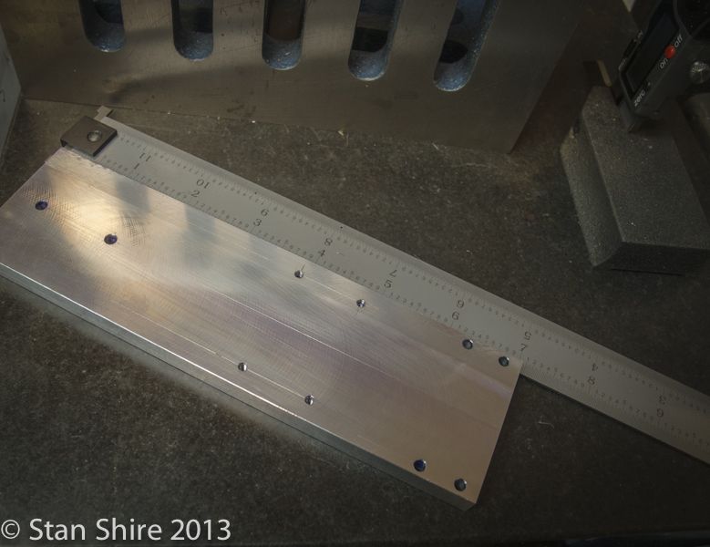
When that was all finished, I flipped the piece over and did the counterbores.
And done.
Im going to do the bearing block next. The RV-2 was the first engine that I had done with bearings. Im a believer! Ive got some extra .25 ID Boca Bearings from the RV-2 build.
So heres the question.
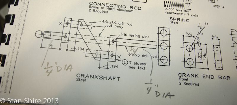
Is there any reason that I shouldnt (or cant) increase the crankshaft ends to .25 (to fit the bearings) from Elmers .1875?
There seems to be plenty of metal available in the bearing block for this increase.
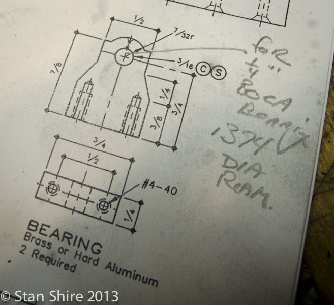
My thought is to only increase the crankshaft ends and leave the middle at .1875.
Elmers #34 - Cross Twin Engine
Part 1
Other than polishing, the Liney RV-2 is done. So, here we go with the next engine.
Ive always wanted to do a horizontal engine and Elmers #34 - Cross Twin Engine seemed intriguing.
After reading the drawings, so that I understand how the engine works, I called my neighbor, Fred, who has a virgin copy of the actual Elmers Engine book. The John-Tom drawings are fine but the pictures look like the result of someone who has a $3.00 scanner and has no idea how to use it. As far as I could tell, the picture was either an engine or a Koala in heat. Having the book, with Elmers very clear pictures, is a major help.
I started with the base. 6061 aluminum plate. My normal procedure is to mark the piece as a sanity check with the DRO.

After cutting a rough-size piece, squaring and sizing it from the 3/8 6061 plate, spot drilling, drilling and tapping commenced.
All holes were put in as SDM (sub data memory) in the DRO. This way I can do all spot drilling, then all drilling, then all tapping just by going to the 10 sub-data points.

When that was all finished, I flipped the piece over and did the counterbores.

And done.

Im going to do the bearing block next. The RV-2 was the first engine that I had done with bearings. Im a believer! Ive got some extra .25 ID Boca Bearings from the RV-2 build.
So heres the question.
Is there any reason that I shouldnt (or cant) increase the crankshaft ends to .25 (to fit the bearings) from Elmers .1875?
There seems to be plenty of metal available in the bearing block for this increase.

My thought is to only increase the crankshaft ends and leave the middle at .1875.


