Cutting a cam with radiused flanks

Home Model Engine Machinist Forum

Help Support Home Model Engine Machinist Forum:

This site may earn a commission from merchant affiliate links, including eBay, Amazon, and others.
Vietti--I don't run my mill in reverse with a boring tool in it, because I am afraid the boring head will unscrew itself apart and cause a disaster. Not all boring heads will do this, but mine will.---Brian
 
Be careful running boring heads in reverse, many screw onto the arbor and could come undone.

If you don't want to make a special tool a quick regrind of a righthand one make sit usable for external cuts when running in the usual direction

DSC01244_zpsz46mbks0.jpg
 
So, here we have a 3D model of the larger cam cutter, which will cut a cam the same size as the one used on my T-head engine, and the finished part in steel.--as finished 5 minutes ago. all I have to do now is cut a cam and see if it works.
ZPf6fc.jpg

ETrHvV.jpg
 
I turned a piece of 1" diameter round stock to an outer diameter of 0.764" as called for on the drawing, mounted it in my machine vice and centered the mill spindle over the center hole which is reamed to 0.375". I then offset the spindle in the y axis by 0.200" as called for on the drawing, and offset the spindle 0.346" in the x axis, again as called for on the drawing. I zeroed out the vertical tool position at the point where the tool contacted the top of the workpiece, put my mill into low range, and used the manual low speed advance to move the tool vertically 0.400". This took about 5 minutes. I then offset the spindle 0.346 in the opposite direction and took another cut to a total depth of 0.400". this again took about 5 minutes.
PVCEVt.jpg
 
After cutting the two flanks in the previous step, I moved over to the 3 jaw chuck mounted on my rotary table and machined away the remaining material exactly as I explained earlier in this thread. that took about 10 minutes.
l6jomw.jpg
 
I then moved the material over to my lathe and polished it with some 200 grit paper.---What do I think?--I think this is absolutely awesome!!! It took less than an hour to make the cam, start to finish. Now this was a "try out", using a piece of 1045 cold rolled shafting. If it was a real cam I would have machined it from 01 material so I could flame harden it. However, unhardened 01 material machines about the same as any cold rolled steel, so I don't anticipate any problem there. thanks everybody for watching.---Brian
HGadYH.jpg
 
Thanks Brian, I knew there was a simple way to make cams when one doesn't have a CNC miller! I must plan a model with cams so I can have a play! (After the dozen jobs still to complete?).
Your brilliance lies in simplicity. I had thought the use of a side mill was the "simple" way, but the surface "grain" from a milling cutter would not be as good from a "cam-follower rubbing action" perspective as the tool you made. Your tool will apply the cutting surface marks in-line with cam-to-follower interaction so need less polishing after hardening. Will your steel take nitriding instead of case hardening? Done the same way as case-hardening but using High Nitrogen fertilizer as a nitrogen additive powder? (I haven't tried it, but was told "That's the way to do it!" decades ago.). I have also (inadvertently!) case-hardened mild steel tube by using a carbon-arc torch on my weld set to braze steel brackets onto exhaust pipes. I had decided to post-drill the brackets after brazing, tweaking, etc. to fit and took the edge off a new high speed steel twist drill trying to penetrate the hard carbonized skin. - Used a cobalt steel centre drill in the end.
K2
 
It's curious that no one mentioned that it's best to only use a drill chuck for drilling. A chuck will flex on high lateral loads thereby causing chatter and inaccuracies. Yes I'm guilty of it also but only when counterboring holes with an end mill. Even then you have to be careful otherwise the end mill will turn into an ugly boring bar.
 
Jason--I lay in bed last night trying to see how your method of holding the blank in the three jaw chuck on the rotary table would work better than holding my part in the vice. I finally figured it out. It WOULD work better than transferring the part from the vice to the three jaw chuck, as you would never lose track of exactly where the high point on the cam was.---Sometimes it takes me a while------Brian
 
Just by coincident, I found this video of a man making a cam lobe using the Edgar Westbury/Bob shores offset turning jig.
watch

watch
 
And here is the Randall Cox method of cutting a cam using a boring head running in reverse. This method again requires many, many cuts in 4 degree increments. It's close to my method, but my method does not require many steps to cut the cam.
 
Some good stuff in the videos. I prefer the "boring bar" method I think?
These videos show very well the principles involved, even if some of the details are a little imperfect.
Of course, as much as possible, stiffness of tools and workpiece and mounting is paramount to accurate machining. If things "move" use a smaller cut, slower feed, etc. until repeatable accuracy is achieved.
And be aware of maximum cutting speeds for the material.
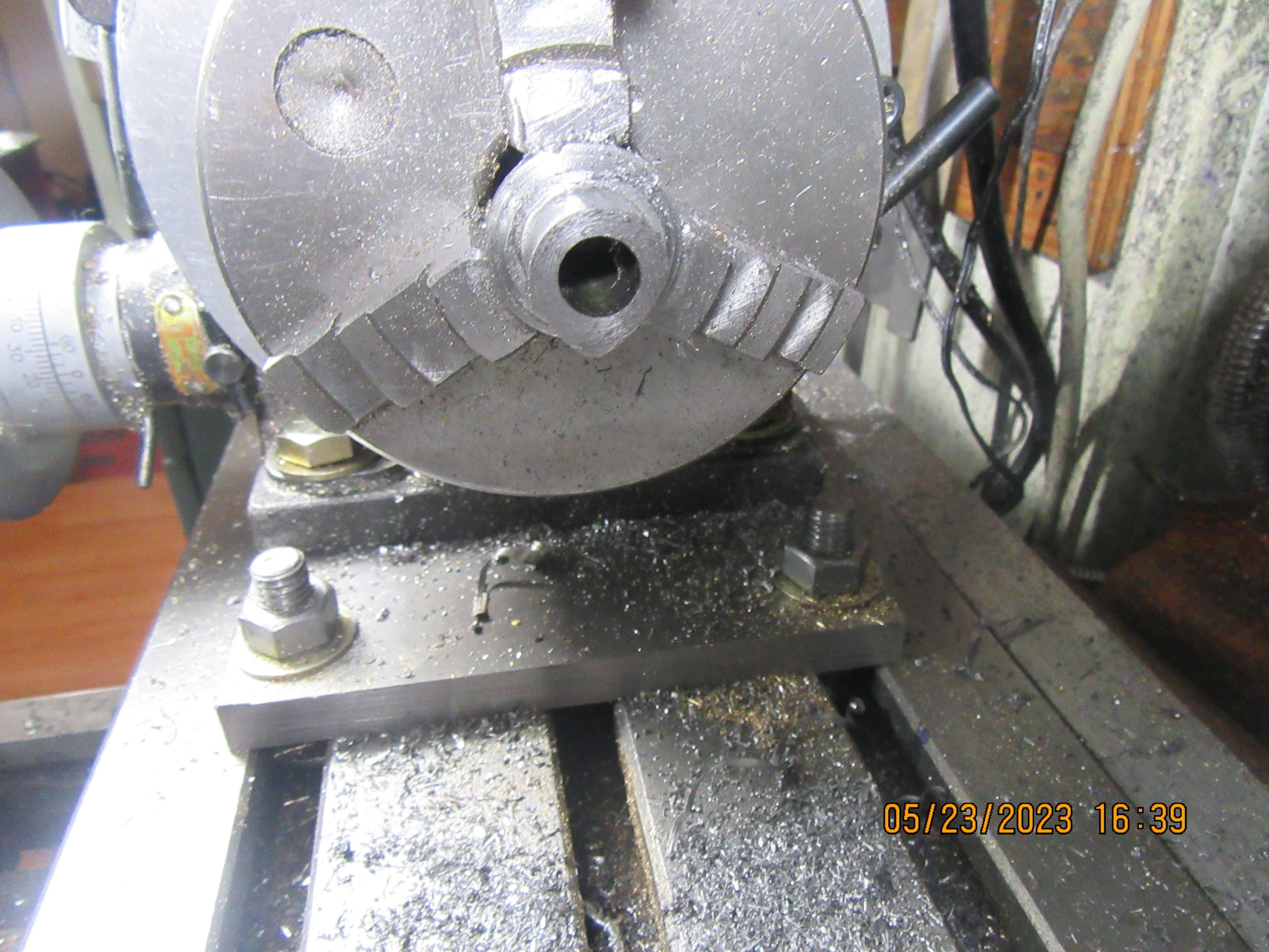
I was taught "slowly, slowly, catchy monkey" - which also applies to repeatable accurate machining, especially of tougher materials like silver steel, or weaker, more flexible materials like aluminium. Often the most flexible part is the workpiece. Perhaps in the Hoglet aluminium demo it would have been better to have a bar at full size, instead of using the recessed grooves between the cams, then turning shafts down to size and the grooves after making the cams? If the original is a bar with centres in both ends, then this means the final lathe setting can be between centres and accuracy is maintained.
Please correct me if I have got this wrong? I'm just learning!
K2
 
I think it is always better to have the shaft supported on both ends. Of course, that being said, I have made at least 50 cams with the material supported at one end only. If the parent material you are cutting the cam from is at least 3/4" diameter and it is held securely by one end, than it won't move enough that you will notice it. On the video posted by Andrew Whale, the material was definately moving around as he was cutting it.
 
.............., instead of using the recessed grooves between the cams, then turning shafts down to size and the grooves after making the cams? If the original is a bar with centres in both ends, then this means the final lathe setting can be between centres and accuracy is maintained.
Separating the cam blanks by grooving first gives you free air to put on the cut and run the tool out at the end of each of the three lobes

Brian, you tend to only cut single cam lobes so don't have much stick out so you won't get the possibility of flexing that the longer Hoglet cam can cause as there are effectively 4 cams on that one piece not just a single one. Hoglet cams are also more slender than your usual ones on a 3/8" shaft, they are on a 1/4" shaft

That big CSK screw he is using to clamp the tool bit is not going him any favours either as he needs a lot of material sticking out of the collet so the clamp screw won't hit it. Compare that to my earlier picture where the tool is held by a grub screw from the side
 
Last edited:
It's curious that no one mentioned that it's best to only use a drill chuck for drilling. A chuck will flex on high lateral loads thereby causing chatter and inaccuracies. Yes I'm guilty of it also but only when counterboring holes with an end mill. Even then you have to be careful otherwise the end mill will turn into an ugly boring bar.
It's been mentioned to Brian before...... But you know, some times them old dogs......:cool:
 
Steamchick,
I use a regular 1/2" R8 (not collet) holder in my spindle. I have bushings for 3/8 and 1/4 inch shanked tools. I have several different sized drill chucks mounted on 1/2 shanks. To change tools it's just a matter of loosening the set screw and swapping out whatever tools I need. Quick and easy!
Good machining practices should always tried to be followed!
 
Pileskis is correct.--It would have been a more secure set up if I had held the shank of my new cam cutting tool in an R8 holder. I only have two sizes of R8 holders, one being for 1/2" shanks, the other being for 3/8" shanks. To be honest, I never even thought of using them. The maximum diameter my drill chuck will take is 5/8", so that's what I made the shank on my new tool from.
 

Latest posts

Back
Top