


Cedge
Well-Known Member
- Joined
- Jul 12, 2007
- Messages
- 1,727
- Reaction score
- 28
Warning.... this will be a long post with heavy photo content. Strong Coffee and heavy Donut supplies should be laid in before attempting to read it all in one go.
When I began the Water Pressure Engine Project, the idea of using curved spoked flywheels quickly floated to the top of the "I want" list. Powderkeg was gracious enough to offer me a pair of his cast flywheels, but his work circumstances and some serious health issues made it impractical for him to do so. I still thank him for his generous offer, but I also told him to concentrate on the important real life issues and forget about the castings.
Bogstandard came to my rescue by sharing an article written by the legendary Philip Duclos. The article shared the secrets of manually machining curved spoke flywheels. At first glance, the instructions were a little intimidating but after a little study, a couple of things became clear. Philip Duclos was a genius with a flair for making potentially difficult things easy to understand. As I progressed, I also learned that he had boiled the process down to its most essential form. No wasted steps and no wasted advice... he gave it all to you in as few words as were required to get the job done.
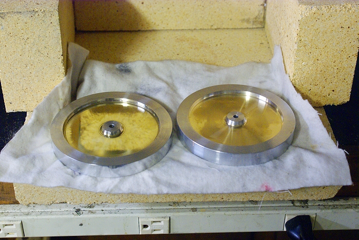
Once I was relatively sure of the process Duclos described, I decided to give it a go. The first step was to come up with blanks of the right size for the engine. After some testing, the engine looked best with 4 1/2 inch diameter wheels. Since I only had 3 1/2 and 4 inch brass and no cast iron, I decided to build the blanks by pressing the brass inside aluminum rims. This lead to choosing a 3 piece design where the inner hub would be aluminum, the spokes brass and the outer rim in aluminum.
Flywheel blanks after press fitting and surfacing for mill cutting
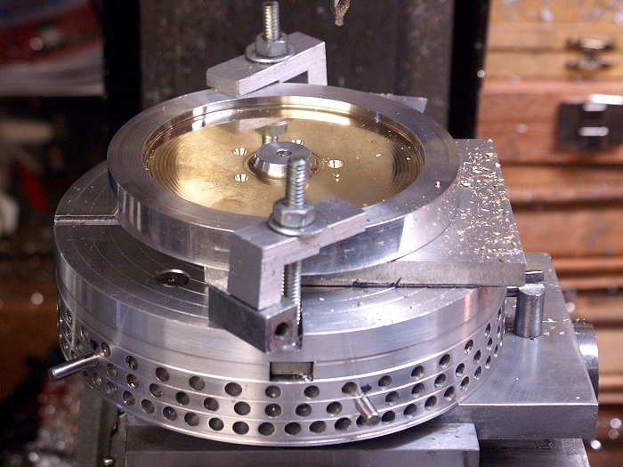
The center holes were reamed to 3/16 so that I could use a 3/16 dowel pin for centering purposes as well as for adding stability to the set up when the blanks were placed on the rotary indexer. Since I didn't have a rotary table until a couple of weeks after this project was completed, my handy dandy home made manual indexer was Hobson's choice for the project.
You'll notice the blank is placed atop a piece of 3/8 aluminum plate. This plate will become a very important milling ji,g as we go along. It too was reamed for the 3/16 dowel pin and was visually squared and a witness mark was made on the indexer for quick positioning when required.
Blank mounted on the indexer in preparation for creating the milling jig

The process began with locating the required holes which would serve as the corners of the openings between spokes. For a 5 spoked wheel, the wholes are located at 72° intervals, 5 at the hub and 5 at the outer rim. These were first center drilled and the placement from the hub was noted for double checking when drilling the actual holes.
The blank with 5 of the first 10 locations being center drilled.
The larger holes form the corners of the opening at the hub while they form only one corner of the outer rim. The typical straight spoked flywheel would have the same size holes on either side of the spoke, but not when doing curved spokes. The opposing side will require a much smaller hole to allow for the curves.
The large diameter (7/16 in.) corner holes drilled to size

Here you can see the complete set of holes. The smaller holes allow for a tighter corner radius than the larger corner holes. This gives a nice graceful blending of both sides of the spokes into the rim of the flywheel.
All the required holes have been located and drilled prior to cutting the openings

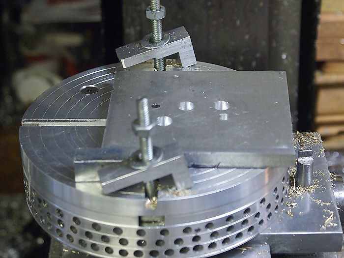
The first 4 holes drilled were specified by Duclos so that they could be used to form a milling jig. The first 2 inner holes and the first 2 other holes were drilled into the sub-plate beneath the flywheel blank. This jig is used to position the flywheel and to prevent movement of the work piece as the heavy milling is done. They also served as reference points for sizing and locating the pivot points for the cutting arcs.
The milling jig with the corner holes in their proper places
The curvature of the spokes can be varied, although Mr. Duclos made no mention of this fact. I discovered this while tinkering with pencil drawings that I used to wrap my head around the project. Since Duclos suggested that different sized flywheels would require reducing or increasing his dimensions, the pencil drawings were an excellent aid and helped me see how the curves and holes related. This exercise let me go for a different curvature than his instructions showed.
The alteration is done by varying the diameter of the 2 radii of the second small template that had to be made. The template tool is made with 2 different radii, allowing one template to be used to lay out the arcs for both sides of the spokes.
The second template being used to locate the "inside arc " pivot points on the milling jig

In the above photo, the dowel pins are in two holes of the same size. This allows the center point to fall on the centerline between them. The drill bit is used to mark the location so that a 3/16 in hole can be reamed to accept the 3/16 dowel pin that will be used as the pivot point for the inside cut.
The photo below shows the second pivot point being located. The 3rd large hole is from of the adjacent cut out, since it is located on the opposing side of the spoke. It will have a larger radius, but the use of the 7/16 inch dowel pin and the smaller 1/4 inch pin throws the pivot off the centerline and creates an offset that will effectively control the amount of taper the spokes will have. As mentioned previously, varying these two arcs will let you vary the visual style and taper. The 2 new 3/16 holes will become placed over the indexer's center pin so that any rotation is centered on the arcs of the spokes.
The second template being used to locate the offset of the "outside arc" pivot points on the milling jig

Here's where the sweating began...and Brian, I definitely know the feeling well. The small 1/4 inch dowel was used as an anchor while cutting the inside arcs of the spokes. The large holes took some of the stress out of the operation by providing an "escape" point that didn't require intense attention to the DRO. The cuts were made to the final dimensions which is something I would do differently on the next project. Leaving about 1/64 of material would have made final clean up much, much easier. The cutter was a 3/16 inch 4 flute which made multiple cuts to prevent breakage or heavy deflection.
The inner arcs are cut... note the work piece offset and dowel pin used for indexing the flywheel

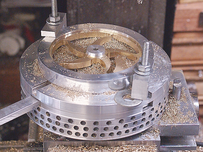
Here you can see the "outer" curves being cut. Once these cuts were completed, the spokes were visible for the first time. It was still hard to see the final shape but the curves were now there and things were getting a lot less stressful. A word to the wise... when the stress comes off too early, look out... the gods are just about to have a belly laugh at your expense.
The outer arcs being cut... again...note the work piece offset and dowel pin used for indexing the flywheel

The next series of cuts got me into trouble. Milling the slots along the outer rim took place after the "stress relief" had occurred. Like I said... look out!! The rhythm of repeating cuts set in and when I got momentarily distracted, I dropped the quill down and began a cut from the wrong end of the slot that I was cutting. This resulted in the end mill doing some serious climb cutting, which wasn't noticeable until it exited the slot. When it escaped into the "safety" of the large drill hole, it never slowed down.
The results of that brie moment of inattention was a cutter sitting halfway through the previously freed spoke right along the outer rim. No.. I didn't throw the part, but the air was distinctly blue for a few minutes. What had seconds ago been a perfectly curved spoke now had a huge chunk missing and hiding it from view was not an option. At times like this, I've learned to just stop and walk away for a bit. When i returned, I sat down and began to study the damage. Then i picked up a file and began picking at the damage to see what could be done. In a matter of minutes the situation went from a bummer to excitement. There in front of me was a perfect example of the classic Cretors style S spoke.
If you look closely, you can see where the "mistake" is being added to each spoke
After the panic and excitement of finding such an easy and attractive solution. the rest of the project was almost anticlimactic. The spokes were cut and the S spokes were uniform, so the rest of the action was doing clean up. As I mentioned earlier... I made the foolish mistake of going for finish depths when making the cuts. Now the tool marks had to be hand filed due to the thin rim my design. I continued the hand flining and added rounded edges to the spokes. The rest... as they say was history.

Steve
When I began the Water Pressure Engine Project, the idea of using curved spoked flywheels quickly floated to the top of the "I want" list. Powderkeg was gracious enough to offer me a pair of his cast flywheels, but his work circumstances and some serious health issues made it impractical for him to do so. I still thank him for his generous offer, but I also told him to concentrate on the important real life issues and forget about the castings.
Bogstandard came to my rescue by sharing an article written by the legendary Philip Duclos. The article shared the secrets of manually machining curved spoke flywheels. At first glance, the instructions were a little intimidating but after a little study, a couple of things became clear. Philip Duclos was a genius with a flair for making potentially difficult things easy to understand. As I progressed, I also learned that he had boiled the process down to its most essential form. No wasted steps and no wasted advice... he gave it all to you in as few words as were required to get the job done.
Once I was relatively sure of the process Duclos described, I decided to give it a go. The first step was to come up with blanks of the right size for the engine. After some testing, the engine looked best with 4 1/2 inch diameter wheels. Since I only had 3 1/2 and 4 inch brass and no cast iron, I decided to build the blanks by pressing the brass inside aluminum rims. This lead to choosing a 3 piece design where the inner hub would be aluminum, the spokes brass and the outer rim in aluminum.
Flywheel blanks after press fitting and surfacing for mill cutting
The center holes were reamed to 3/16 so that I could use a 3/16 dowel pin for centering purposes as well as for adding stability to the set up when the blanks were placed on the rotary indexer. Since I didn't have a rotary table until a couple of weeks after this project was completed, my handy dandy home made manual indexer was Hobson's choice for the project.
You'll notice the blank is placed atop a piece of 3/8 aluminum plate. This plate will become a very important milling ji,g as we go along. It too was reamed for the 3/16 dowel pin and was visually squared and a witness mark was made on the indexer for quick positioning when required.
Blank mounted on the indexer in preparation for creating the milling jig
The process began with locating the required holes which would serve as the corners of the openings between spokes. For a 5 spoked wheel, the wholes are located at 72° intervals, 5 at the hub and 5 at the outer rim. These were first center drilled and the placement from the hub was noted for double checking when drilling the actual holes.
The blank with 5 of the first 10 locations being center drilled.
The larger holes form the corners of the opening at the hub while they form only one corner of the outer rim. The typical straight spoked flywheel would have the same size holes on either side of the spoke, but not when doing curved spokes. The opposing side will require a much smaller hole to allow for the curves.
The large diameter (7/16 in.) corner holes drilled to size
Here you can see the complete set of holes. The smaller holes allow for a tighter corner radius than the larger corner holes. This gives a nice graceful blending of both sides of the spokes into the rim of the flywheel.
All the required holes have been located and drilled prior to cutting the openings
The first 4 holes drilled were specified by Duclos so that they could be used to form a milling jig. The first 2 inner holes and the first 2 other holes were drilled into the sub-plate beneath the flywheel blank. This jig is used to position the flywheel and to prevent movement of the work piece as the heavy milling is done. They also served as reference points for sizing and locating the pivot points for the cutting arcs.
The milling jig with the corner holes in their proper places
The curvature of the spokes can be varied, although Mr. Duclos made no mention of this fact. I discovered this while tinkering with pencil drawings that I used to wrap my head around the project. Since Duclos suggested that different sized flywheels would require reducing or increasing his dimensions, the pencil drawings were an excellent aid and helped me see how the curves and holes related. This exercise let me go for a different curvature than his instructions showed.
The alteration is done by varying the diameter of the 2 radii of the second small template that had to be made. The template tool is made with 2 different radii, allowing one template to be used to lay out the arcs for both sides of the spokes.
The second template being used to locate the "inside arc " pivot points on the milling jig
In the above photo, the dowel pins are in two holes of the same size. This allows the center point to fall on the centerline between them. The drill bit is used to mark the location so that a 3/16 in hole can be reamed to accept the 3/16 dowel pin that will be used as the pivot point for the inside cut.
The photo below shows the second pivot point being located. The 3rd large hole is from of the adjacent cut out, since it is located on the opposing side of the spoke. It will have a larger radius, but the use of the 7/16 inch dowel pin and the smaller 1/4 inch pin throws the pivot off the centerline and creates an offset that will effectively control the amount of taper the spokes will have. As mentioned previously, varying these two arcs will let you vary the visual style and taper. The 2 new 3/16 holes will become placed over the indexer's center pin so that any rotation is centered on the arcs of the spokes.
The second template being used to locate the offset of the "outside arc" pivot points on the milling jig
Here's where the sweating began...and Brian, I definitely know the feeling well. The small 1/4 inch dowel was used as an anchor while cutting the inside arcs of the spokes. The large holes took some of the stress out of the operation by providing an "escape" point that didn't require intense attention to the DRO. The cuts were made to the final dimensions which is something I would do differently on the next project. Leaving about 1/64 of material would have made final clean up much, much easier. The cutter was a 3/16 inch 4 flute which made multiple cuts to prevent breakage or heavy deflection.
The inner arcs are cut... note the work piece offset and dowel pin used for indexing the flywheel
Here you can see the "outer" curves being cut. Once these cuts were completed, the spokes were visible for the first time. It was still hard to see the final shape but the curves were now there and things were getting a lot less stressful. A word to the wise... when the stress comes off too early, look out... the gods are just about to have a belly laugh at your expense.
The outer arcs being cut... again...note the work piece offset and dowel pin used for indexing the flywheel
The next series of cuts got me into trouble. Milling the slots along the outer rim took place after the "stress relief" had occurred. Like I said... look out!! The rhythm of repeating cuts set in and when I got momentarily distracted, I dropped the quill down and began a cut from the wrong end of the slot that I was cutting. This resulted in the end mill doing some serious climb cutting, which wasn't noticeable until it exited the slot. When it escaped into the "safety" of the large drill hole, it never slowed down.
The results of that brie moment of inattention was a cutter sitting halfway through the previously freed spoke right along the outer rim. No.. I didn't throw the part, but the air was distinctly blue for a few minutes. What had seconds ago been a perfectly curved spoke now had a huge chunk missing and hiding it from view was not an option. At times like this, I've learned to just stop and walk away for a bit. When i returned, I sat down and began to study the damage. Then i picked up a file and began picking at the damage to see what could be done. In a matter of minutes the situation went from a bummer to excitement. There in front of me was a perfect example of the classic Cretors style S spoke.
If you look closely, you can see where the "mistake" is being added to each spoke
After the panic and excitement of finding such an easy and attractive solution. the rest of the project was almost anticlimactic. The spokes were cut and the S spokes were uniform, so the rest of the action was doing clean up. As I mentioned earlier... I made the foolish mistake of going for finish depths when making the cuts. Now the tool marks had to be hand filed due to the thin rim my design. I continued the hand flining and added rounded edges to the spokes. The rest... as they say was history.
Steve
 Sadly, your Donut warning came around 4 minutes after the local store shut :wall: ............... however coffee is always on hand so I tackled the post only 75% armed ......... (we do have choccy biccy's in stock) ............ ;D