Casting a tapping guide arm for my drill press

Home Model Engine Machinist Forum

Help Support Home Model Engine Machinist Forum:

This site may earn a commission from merchant affiliate links, including eBay, Amazon, and others.

CallMeAL

Member
Joined
Mar 29, 2008
Messages
118
Reaction score
40
Hello,
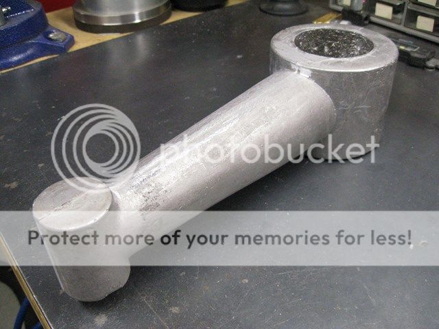
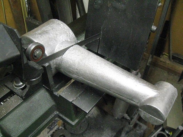
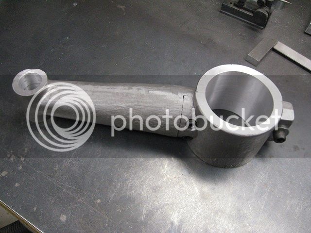
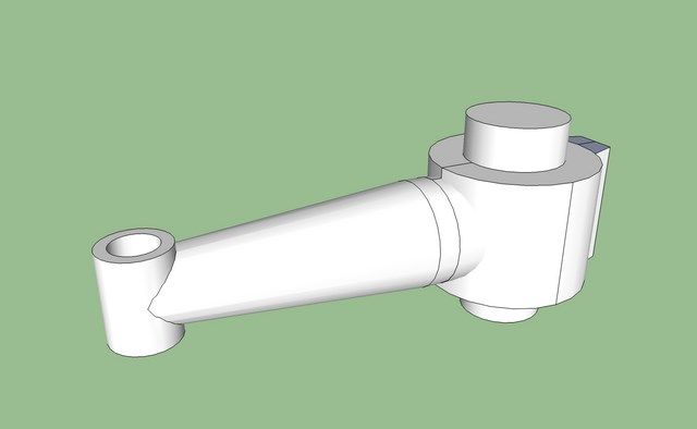
In my wandering on the net and in tool catalogs, I have seen various renditions of a tapping guide machines. I thought it would be interesting to try to make one, more of a challenge to use my foundry and machine tools rather than something I really need. My intention is to cast a guide arm that will attach to the column of my drill press and use the adjustable table to allow a great deal of flexibility. Also, since I have a small shop, I will be able to combine two tools in one without taking up a lot more space!

Here is the model of the pattern I came up with in Sketchup:

DrillguideCopy.jpg


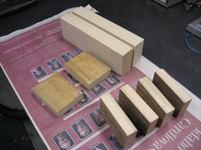
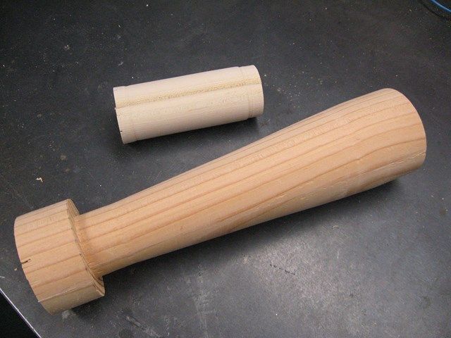
I chopped up some scrap wood to turn parts for this pattern

IMG_1677Copy.jpg


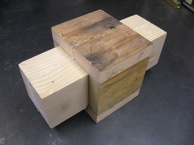
This will be a split pattern so here is what the glue up looks like with a sheet of paper glue into the mid-line.

IMG_1679Copy.jpg


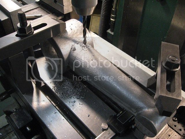
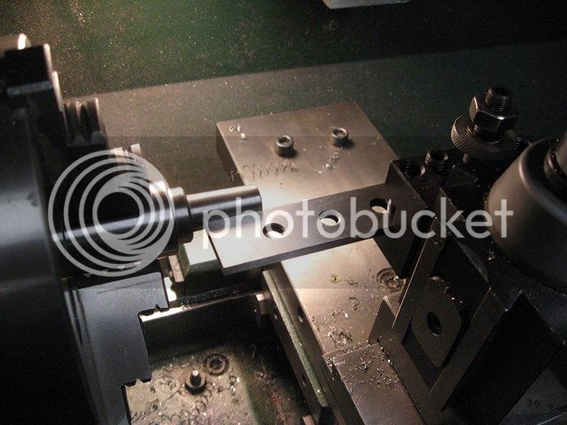
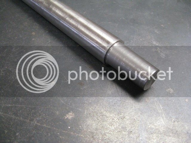
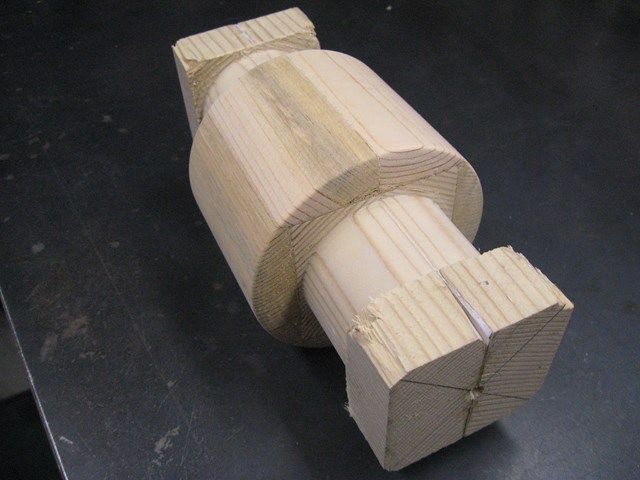
Here is the main body turned with the ends left square so I could drill the hole for the arm with the biggest forester bit I have.

IMG_1700Copy.jpg


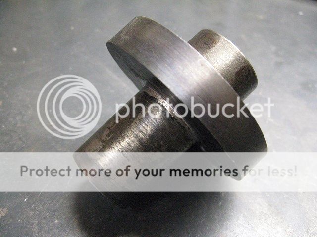
The other two pieces of the split pattern.

IMG_1702Copy.jpg


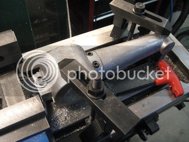
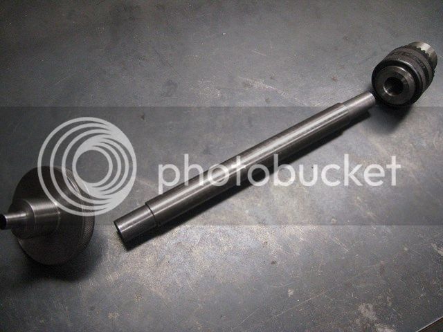
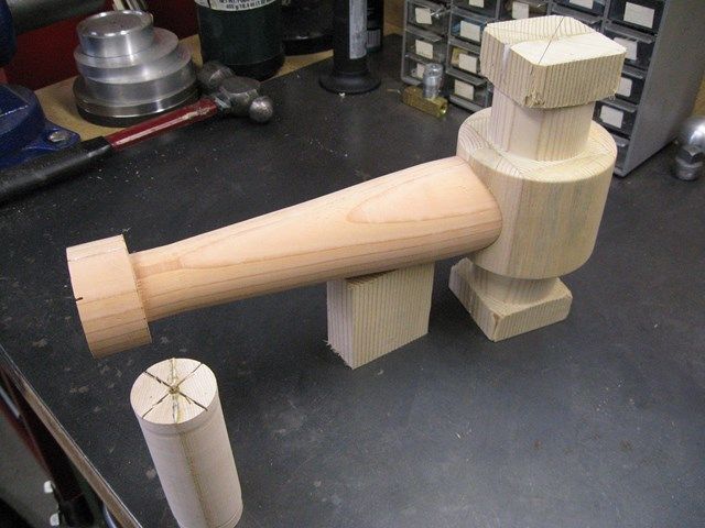
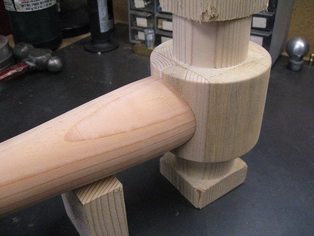
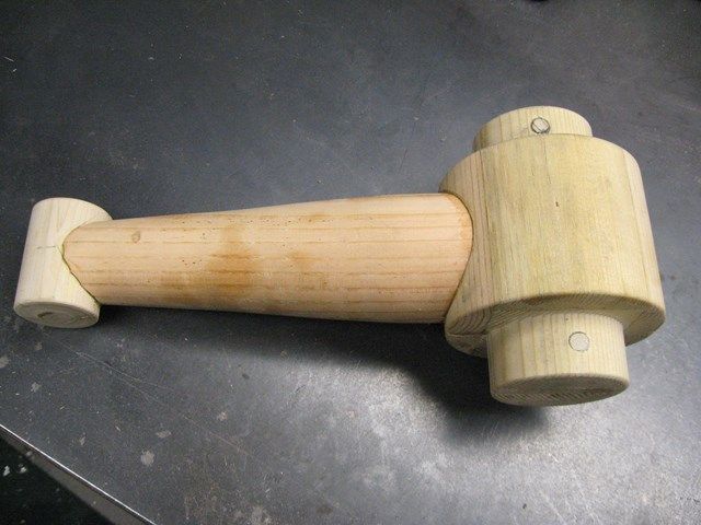
Hole drilled for the arm and test fit.

IMG_1704Copy.jpg


IMG_1705Copy.jpg


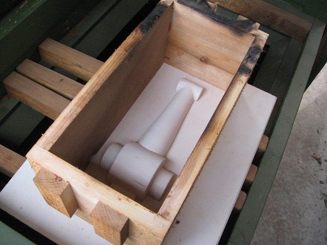
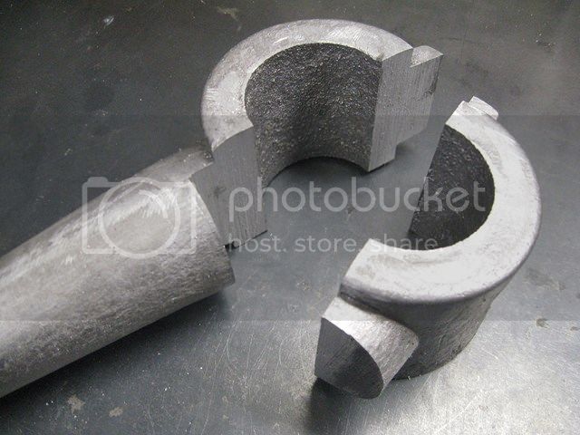
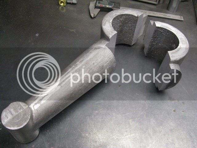
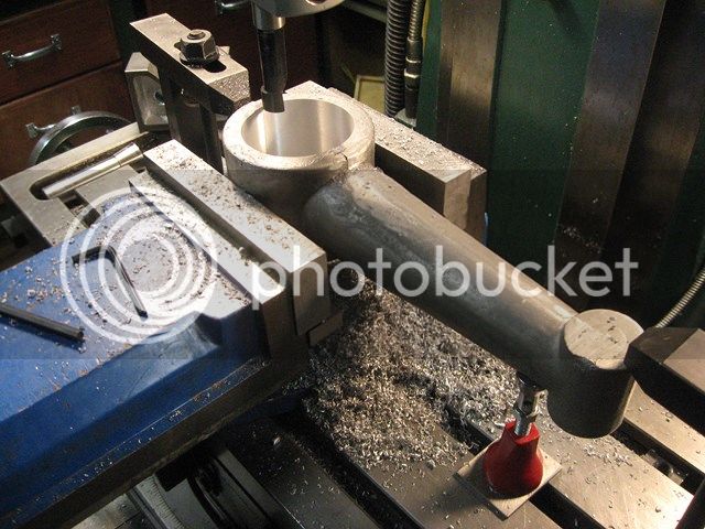
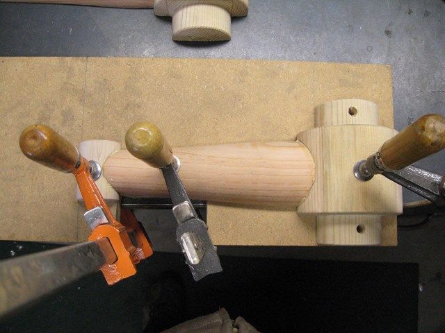
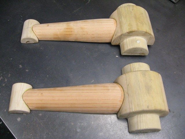
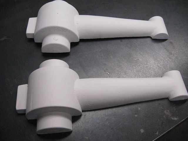
Ends trimmed off, patterns split apart, and glued up. Locating dowel holes were drilled before splitting apart.

IMG_1708Copy.jpg


The holes were drilled into the protrusions for the core print.
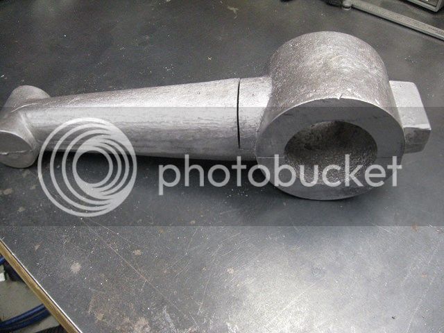
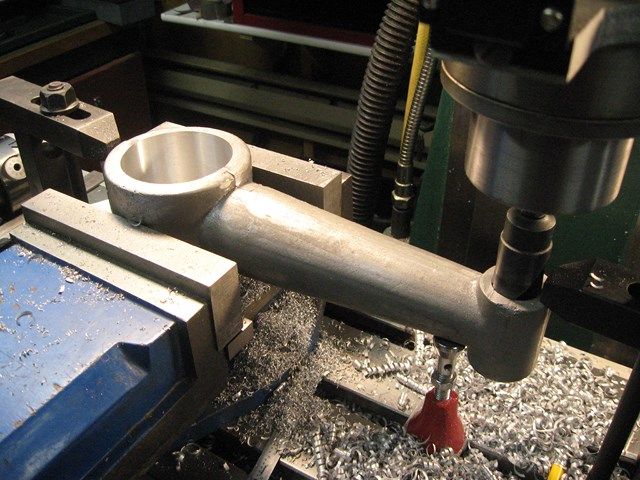
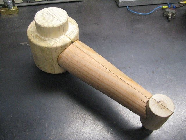
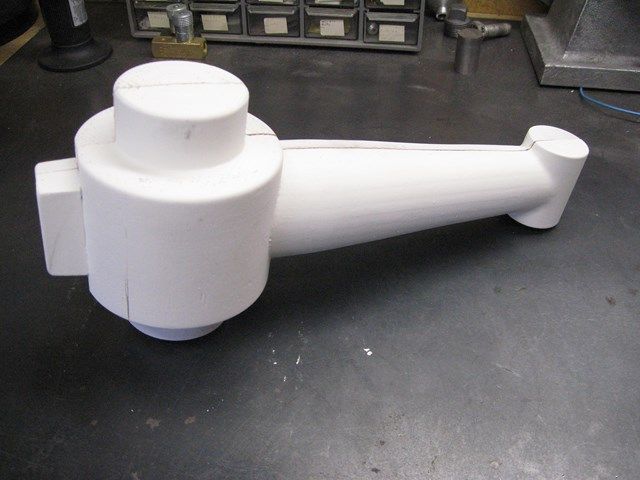
Pattern glued up.

IMG_1709Copy.jpg


IMG_1712Copy.jpg


IMG_1711Copy.jpg
.

IMG_1714Copy.jpg


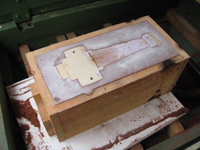
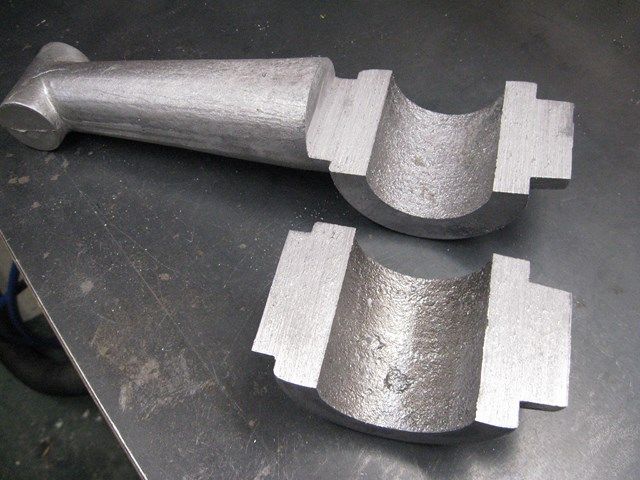
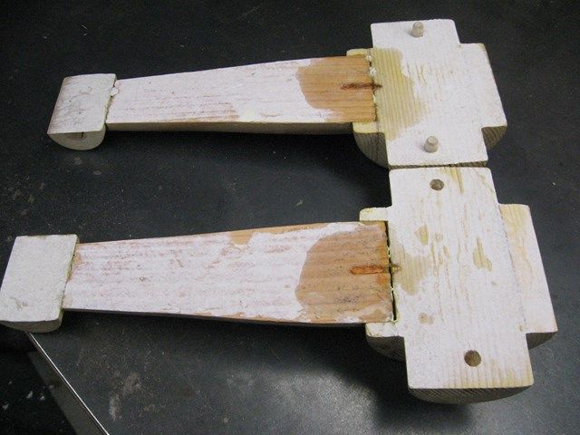
Sanded, a little spackle filler in places, and primer applied.

IMG_1719Copy.jpg


IMG_1720Copy.jpg


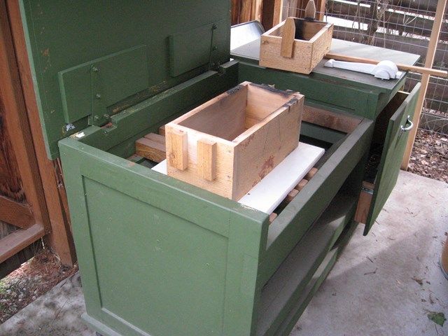
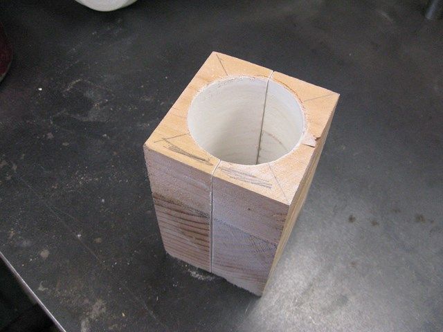
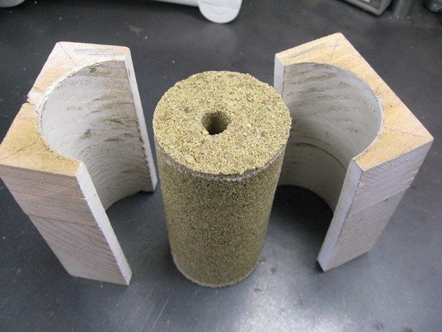
Glued up the core box and drilled out the hole with the same forester bit.

IMG_1721Copy.jpg


IMG_1722Copy.jpg


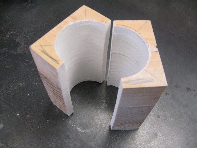
Mixed up some sand and sodium silicate, tamped it into the core box, and put it in a plastic bag with CO2 from my wire feed welder and made the core for the hole in the casting for the drill press column. The hole in the center is to allow the CO2 get into the middle of the core.

IMG_1726Copy.jpg


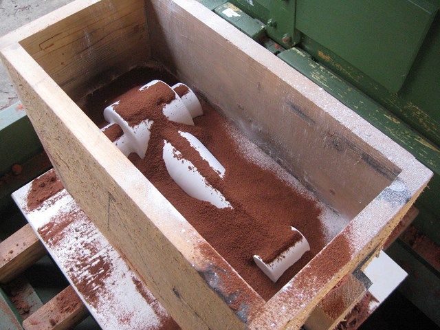
Now that I have the pattern done I hope to ram it up and cast the arm tomorrow. It's a long process to get to this point, but if the pour goes well it is worth it. It's fun to see the casting come out of the sand!

More to come!

Thanks for your interest.
 
Cool! Thor's Hammer!

Or that's what I thought before I read the post AL ;-)

Seriously though, Im very interested in what your doing here as my efforts to date at casting have been somewhat less than awesome! It's always great and very helpful to see how people approach projects, and the results along the way. Video of the casting would be good!

cheers, Ian
 
Hi Al
Looking forward to the pour!
Pete
 
Thanks for the comments aarggh and metalmad.

Sorry I didn't get any video of the pour, it was threatening rain so I was busting as to it done.
 
I'm kind of sparse on pictures of the ram up of the flask and the actual pour, but sandy hands, hot metal and cameras don't mix, it looked like it was going to rain, and I just got wrapped up in doing the process and forgot take as many pictures as I would liked to.
Here is my molding bench at the start of ramming up the flask.

IMG_1727Copy.jpg


IMG_1728Copy.jpg


I might point out here I had the drag upside down and did not notice it till I went to put the cope on. It looks nice, but I had to redo it :(

IMG_1729Copy.jpg


Now I got it going the correct way

IMG_1730Copy.jpg


The pour was kind of sloppy. Shaking out the flask.

IMG_1731Copy.jpg


You can see the core poking out.

IMG_1732Copy.jpg


The casting turned out great. Notice the core held together, but it was kind of a chore breaking it out. I had to soak it in water and get after it with a big chisel.

IMG_1734Copy.jpg


The casting turned out very good! Sprue and riser cut off and parting lines filed a bit.

IMG_1741Copy.jpg


IMG_1743Copy.jpg


Now to dig into the machining!
 
How cool is that, you've done this before ;D
I love the casting bench Al
I need to make something like that, is there a slide out sand box on the bottom?
Id love a couple more pics of the casting table to give me a better idea of what to make.;D
Pete
 
Great job on the casting. How is the drive on your DP setup so that you can tap, or are you adding a tapping head to slow down the spindle speed.? Does the arm guide an arbor, or the tap itself.
 
MachineTom: Thanks for the comment. No my drill press will not be used for the tapping. It is only donating it's table, column, and light. The tapping is manual or if my idea works out will use a reversible hand drill which is variable speed.

gus: I am using melted down hydraulic pump cast aluminum housings. What is "de-fetter"?

metalmad: Thanks, Yes I've made several pours and many mistakes, but I learn something each time. Here is a few still shots and video of my bench. It's great to have the mess contained in one area. :)

IMG_1305Upload.jpg


IMG_1307Upload.jpg


[ame]http://youtu.be/GbYw5P0V6As[/ame]
 
That really is a fantastic foundry bench Al, very nicely made!

cheers, Ian
 
callMeAL How much sodium silicate do you use? I use about 4%.

How do you find it when digging out the core? At cast iron temperatures those cores are very hard to remove, also the sand sticks to the metal and I have to remove it using a grinder.
 
Nice job on both the part and bench.
Rob over on Madmodder made one of these about a year or more ago, though his was a weldment that he stressed relieved.
John Stevenson made a good comment on Robs thread about just using the drills original table support with a bush in it for a tapping guide.
It's something to think about for others here that don't want to go to the hassle.

Really nice job on the casting though.

Dave
 
Ian: Thanks, I want to have a bench to contain the mess and tools for ramming up flasks and be able to roll it out with the top folded down and have a good sized work surface for projects outside when the weather is nice.

100model: I did not measure out the sodium silicate. I used just enough to make the sand slightly damp. I have used too much before (sand soggy) and had trouble getting to set up. Yes the cores get very solid after the heat of the pour, but I soaked it in water which seemed to soften it some what. I used a screw driver and masonry chisel it came out and with a little scrubbing I got 99% of the sand out without grinding. It bored out with out destroying the bit!

Dave: Thanks, I have seen Robs work on Madmodder, very impressive. I haven't seen his tap guide though. I got my inspiration from myfordboy on Youtube, though I'm doing my tap guide very different. Bushing the hole in the table or taking the table off and using the hole in the table arm seems like a lot of work every time you want to tap something. With a separate arm you can drill your holes and then rotate the table over and tap them out. I hope to have powered tapping with a hand drill. Stay tuned, hopefully it will work.
 
When I first conceived this project, I thought I would just remove the base and table from the column of the drill press and just slide the arm on and then reinstall the base and table. Well, the more I thought about it and I considered how decrepit I am, I thought it better to try and split the casting and have it bolt together around the column. Better idea! It will be much easier to remove if need to.
I started the cross cut on the band saw then finished the cut and split the casting length ways by hand following the parting line. I turned out surprisingly good.

IMG_1746Copy.jpg


IMG_1747Copy.jpg


IMG_1748Copy.jpg


IMG_1751Copy.jpg


IMG_1750Copy.jpg


Assembled clamped in the mill to drill and tap for the bolts to hold it together so I can bore out the hole for the column.

IMG_1752Copy.jpg


IMG_1753Copy.jpg


Boring for the column.

IMG_1755Copy.jpg


Drilling the small end for the tap chuck shaft bushing.

IMG_1757Copy.jpg


Turned out great

IMG_1759Copy.jpg


Next slit the back for the pinch bolt

IMG_1760Copy.jpg


Ready install tap shaft bushing and mount!

IMG_1762Copy.jpg


So far no mistakes (that I will admit to)! :D
 
Instead of slitting an existing parting joint, I would shim the rear .020 with brass and then the bore the column hole. A little too big a chance of catching the top piece and breaking it off. Must have some big chatter at least
 
Nice!

I've contemplated building a pillar tool for, in part anyways, a tapping stand. This idea gives me an alternative idea to think about.

Obviously you are not done yet, how will you appraoch drilling and boring the other end. Will you do it on the drill press? Your center to center distance should be close to exact that way.

In any event very nicely done bench and all.
 
MachineTom: I thought about doing it that way, but the way I did it I had the parts bolt securely together and got a perfectly round hole. No chatter or interrupted cutting. Slitting it afterword was easy.

Wizard69: Thanks for the comment. If you notice in the above pictures, I drilled out he small end while I had it on the mill and then cut a bushing later to fit the hole with a light press fit. I have a DRO on the mill so I can get the measurement from the drill press column to the center of table hole exact. Unfortunately, though my pattern was exact, I didn't allow for shrinkage in the part and my arm is about .125 of a inch short to get the arbor perfectly centered on the table hole. Oh well, most things will be held in a vice or is the tap is less than 1/2" the table hole will still work. This is the first time part shrinkage has bit me. Live and learn!
 
I test mounted the arm on the drill press - hey I must have measured ok because if fit perfectly. I machined up a brass bushing for the small end and test fitted a piece of ¾ shaft.

IMG_1764Copy.jpg


I set up to cut the taper on the shaft by chucking the morse taper drill chuck adapter I knocked out of the drill chuck I was going to use and put it in a R8 to morse adapter so I could get a round surface to mount in the lathe chuck. Whew, a lot of chucking going on in this sentence. Then I used a parallel to set the compound angle.

IMG_1767Copy.jpg


I stopped cutting when the measurements matched the sample chuck taper.

IMG_1778Copy.jpg


Next I soldered what was going to be the other end on the shaft from scrap pieces to save whittling down big chunk of shaft to get the diameters I wanted.

IMG_1775Copy.jpg


Pieces ready to assemble.

IMG_1777Copy.jpg


The chuck fit great. The other end was turned down and knurled. It is a slip fit on the shaft end and will be pinned to allow assembly.

IMG_1776Copy.jpg


The next thing I wanted to try out was an adjustable friction detent to keep the shaft up when moving the work around. This is sort of experiment. I want it adjustable so I can set it tocompensate for different situations or back it completely off. The knob is soldered up, after knurling,using an Allen head bolt. The brass plunger is to let the spring apply tension without scoring the shaft. My idea came from friction detents on hydraulic valves.
IMG_1769Copy.jpg


Arm drilled, tapped and spot faced for the detent.

IMG_1770Copy.jpg


Seems to work as well as expected. It holds the shaft at any position.

IMG_1773Copy.jpg


Now for the finishing - handle etc. and see how it works!

Thanks for watching.


Hi Al,
This is the reason I enjoy these sites, Homemade tools using the little grey cells that we have all been given................and to those who share their tooling skills I say thank you.
Well done very professional presentation. and a very informative on "How To Construct".
Kindest regards
Beagles
 

Latest posts

Back
Top