


As many of you know, I have just spent a month revisiting my Kerzel engine, in hopes of getting a better "hit and miss" action. One of the things I did was to make a new exhaust cam lobe based on the original drawing be Kerzel. Prior to that, I had been using a cam which I made based on the original Webster cam. I am now trying to wrap my head around the differences in these two cam profiles. in truth, I don't see the engine behaving a lot differently with the new cam than I did with the old cam.
I am getting into the scientific end of cam design and operation, and some of it stretches me.
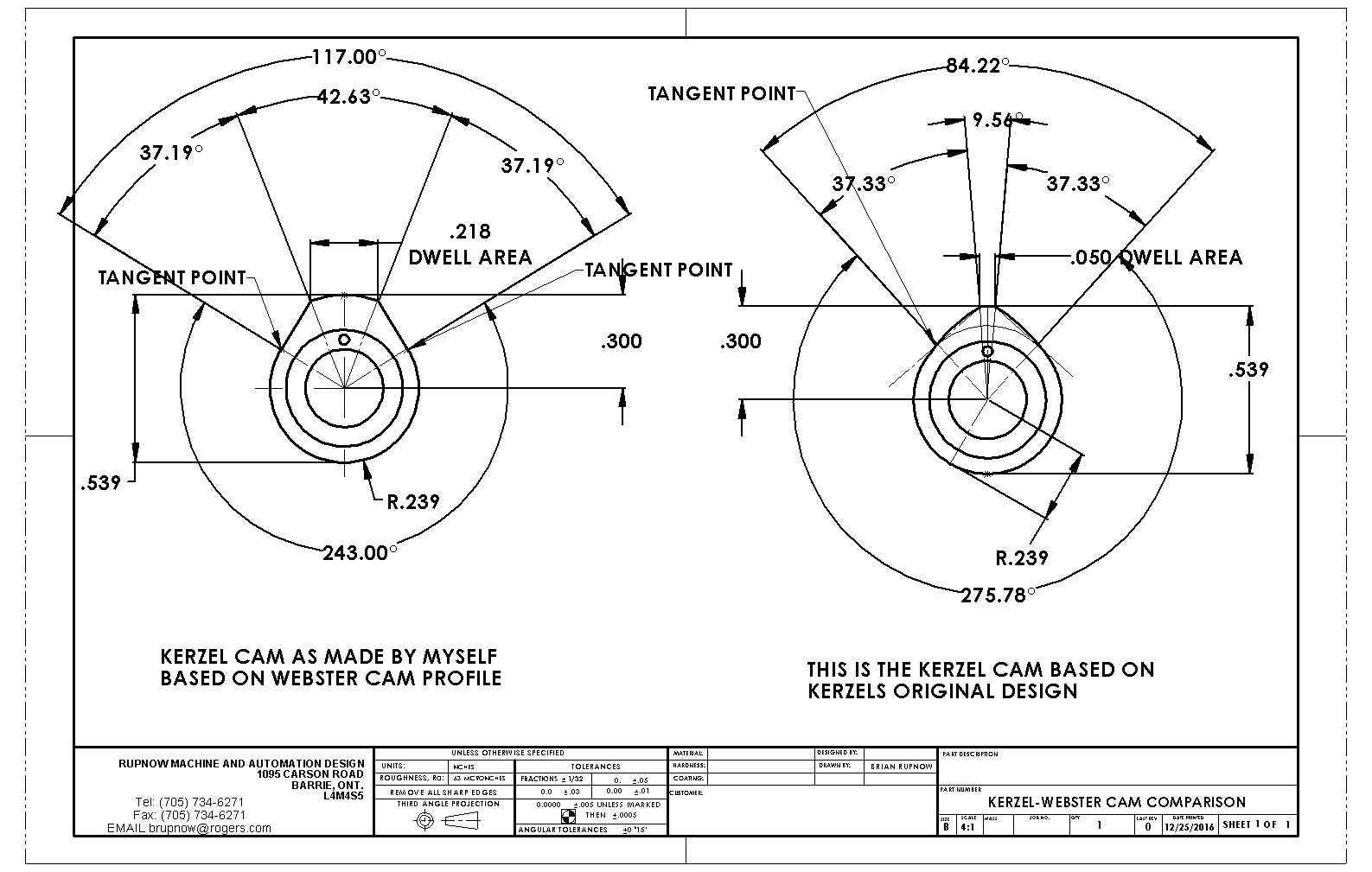
The area on the mainly round portion of the cams at the bottom, which is a true diameter, has no effect at all on the valves. When the lifter or cam follower is riding on these surfaces, there is actually a gap called the "valve lash" between the lifter and other components in the valve train. For purpose of simplicity, we are going to overlook the effect of that "valve lash" in this discussion. It does have some effect on valve timing, but the effect is very small and can be safely ignored on these small engines.
.......It is only the portion of cam that extends beyond the base circle profile that has any effect on the valve, and even then there is a trick. Since the camshaft revolves at only half the speed of the crankshaft, then the 117 degrees on the left hand valve actually has 234 degrees of effect on the valve as relates to the crankshaft, and the 84.22 degrees on the right hand cam has an actual effect of 168.44 degrees on the valve, as related to the crankshaft.
.....The kerzel cam shown on the right is for a slow running hit and miss engine with an atmospheric intake valve, so there is no benefit in having the exhaust valve stay open during a portion of the intake stroke. When the piston moves from bottom dead center thru to top dead center on the exhaust stroke, the crankshaft revolves thru 180 degrees. The Kerzel cam as originally designed by Kerzel exhibits only 168.4 degrees of influence on the valve as related to crankshaft revolution. So ---what does that mean to us? Well, it means that if the Kerzel cam just begins to influence the valve when the piston is at bottom dead center, then by the time the crankshaft has advanced 168. 4 degrees towards top dead center on the exhaust stroke, the valve will have opened, expelled any exhaust in the cylinder, and then fully closed 11.6 degrees before the piston reaches top dead center. Consequently, there is no benefit in having the valve begin to open before the piston reaches bottom dead center.
-----The cam on the left however, was designed for a faster running throttled engine (the Webster), still with an atmospheric intake valve. Again, since the intake valve is atmospheric, there is no advantage in having the exhaust valve stay open during any part of the intake cycle. However, that 117 of cam influence relates to 234 degrees of crankshaft rotation. Since the crankshaft rotates only 180 degrees getting the piston to move from bottom dead center to top dead center, and we want the exhaust valve to be closed by the time the piston gets to top dead center, then we have to begin opening the exhaust valve while it is still 234-180=54 degrees before the piston reaches bottom dead center on the power stroke.--and surprisingly enough, that is almost exactly what Webster asks for in his engine plans.
.....I am still not totally clear as to why the Webster cam has a much wider "dwell" area at 0.218" wide as compared to the 0.050" "dwell" area on the kerzel engine, but I'm sure if I keep plugging away at this cam business it will become clear to me. Notice that both valves go from fully closed to fully open in about 37 degrees of movement, and both close in about 37 degrees of movement. It could very well be that the longer dwell time on the Webster cam is only there to extend the amount of time that the exhaust valve remains open on the Webster, since it is a faster running throttled engine and needs the extended time period to allow time for a full charge of exhaust to leave the cylinder and have no pressure remaining in the cylinder when the piston reaches top dead center and begins it's descent on the intake stroke....Very, very interesting stuff indeed.---Brian
I am getting into the scientific end of cam design and operation, and some of it stretches me.
The area on the mainly round portion of the cams at the bottom, which is a true diameter, has no effect at all on the valves. When the lifter or cam follower is riding on these surfaces, there is actually a gap called the "valve lash" between the lifter and other components in the valve train. For purpose of simplicity, we are going to overlook the effect of that "valve lash" in this discussion. It does have some effect on valve timing, but the effect is very small and can be safely ignored on these small engines.
.......It is only the portion of cam that extends beyond the base circle profile that has any effect on the valve, and even then there is a trick. Since the camshaft revolves at only half the speed of the crankshaft, then the 117 degrees on the left hand valve actually has 234 degrees of effect on the valve as relates to the crankshaft, and the 84.22 degrees on the right hand cam has an actual effect of 168.44 degrees on the valve, as related to the crankshaft.
.....The kerzel cam shown on the right is for a slow running hit and miss engine with an atmospheric intake valve, so there is no benefit in having the exhaust valve stay open during a portion of the intake stroke. When the piston moves from bottom dead center thru to top dead center on the exhaust stroke, the crankshaft revolves thru 180 degrees. The Kerzel cam as originally designed by Kerzel exhibits only 168.4 degrees of influence on the valve as related to crankshaft revolution. So ---what does that mean to us? Well, it means that if the Kerzel cam just begins to influence the valve when the piston is at bottom dead center, then by the time the crankshaft has advanced 168. 4 degrees towards top dead center on the exhaust stroke, the valve will have opened, expelled any exhaust in the cylinder, and then fully closed 11.6 degrees before the piston reaches top dead center. Consequently, there is no benefit in having the valve begin to open before the piston reaches bottom dead center.
-----The cam on the left however, was designed for a faster running throttled engine (the Webster), still with an atmospheric intake valve. Again, since the intake valve is atmospheric, there is no advantage in having the exhaust valve stay open during any part of the intake cycle. However, that 117 of cam influence relates to 234 degrees of crankshaft rotation. Since the crankshaft rotates only 180 degrees getting the piston to move from bottom dead center to top dead center, and we want the exhaust valve to be closed by the time the piston gets to top dead center, then we have to begin opening the exhaust valve while it is still 234-180=54 degrees before the piston reaches bottom dead center on the power stroke.--and surprisingly enough, that is almost exactly what Webster asks for in his engine plans.
.....I am still not totally clear as to why the Webster cam has a much wider "dwell" area at 0.218" wide as compared to the 0.050" "dwell" area on the kerzel engine, but I'm sure if I keep plugging away at this cam business it will become clear to me. Notice that both valves go from fully closed to fully open in about 37 degrees of movement, and both close in about 37 degrees of movement. It could very well be that the longer dwell time on the Webster cam is only there to extend the amount of time that the exhaust valve remains open on the Webster, since it is a faster running throttled engine and needs the extended time period to allow time for a full charge of exhaust to leave the cylinder and have no pressure remaining in the cylinder when the piston reaches top dead center and begins it's descent on the intake stroke....Very, very interesting stuff indeed.---Brian

")
