
You are using an out of date browser. It may not display this or other websites correctly.
You should upgrade or use an alternative browser.
You should upgrade or use an alternative browser.
Building Fred
- Thread starter arnoldb
- Start date


Help Support Home Model Engine Machinist Forum:
This site may earn a commission from merchant affiliate
links, including eBay, Amazon, and others.
arnoldb
Well-Known Member
- Joined
- Apr 8, 2009
- Messages
- 1,792
- Reaction score
- 12
Thank you Gail ") . It's a lot of fun; I can't wait to finish the loco!
. It's a lot of fun; I can't wait to finish the loco!
I managed to grab an hour and a half shop time this evening. Made the regulator-to-boiler fitting from some brass rod bits soldered together. At least I remembered to check where the side that screws onto the boiler bottomed out on its thread, and drilled the hole for the angle piece in the right position so that the regulator would be nice and square. Some more finishing required though; I think I need to take fuzzy photos!:
Regards, Arnold
. It's a lot of fun; I can't wait to finish the loco!I managed to grab an hour and a half shop time this evening. Made the regulator-to-boiler fitting from some brass rod bits soldered together. At least I remembered to check where the side that screws onto the boiler bottomed out on its thread, and drilled the hole for the angle piece in the right position so that the regulator would be nice and square. Some more finishing required though; I think I need to take fuzzy photos!:
Regards, Arnold
arnoldb said:Thank you Gail
No, no, Arnold. That kind of stuff happens enough without trying.
Show us warts and all. We all have a wart or two in the shop, you know.
Dean
arnoldb
Well-Known Member
- Joined
- Apr 8, 2009
- Messages
- 1,792
- Reaction score
- 12
Thank you Dean ;D
Some work on the regulator this evening...
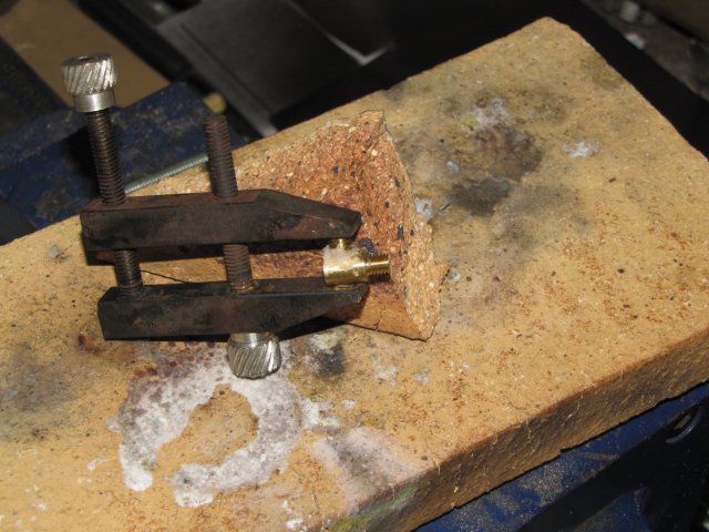
First up some more bits of brass turned & threaded to make the regulator body. Ready to solder on the pipe connection piece on the body; I just filed the bit of threaded brass to fit the contour of the main body. The toolmaker's clamp is showing what frequent use on the firebrick, combined with regular rainy days is doing to it...
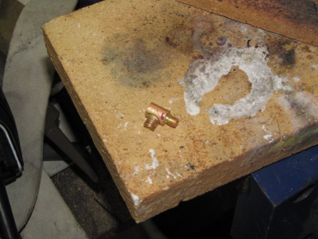
And done... I think my silver soldering is slowly improving:
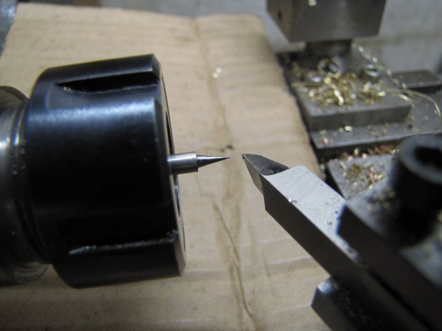
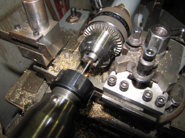
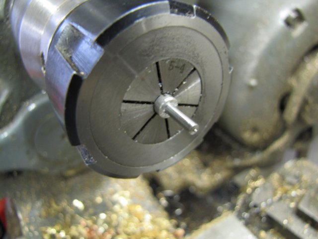
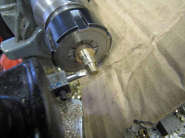
Next up, the valve spindle; some 4mm stainless rod in the collet chuck, turned down to a taper point:
Then it needed to get turned down length-wise for 3mm thread and clearance at the back. I improvised tailstock support using a scrap brass part-off piece with a centered hole (I think this was from my rocking engine's crank!) in the tailstock chuck on the taper on the workpiece; worked a treat:
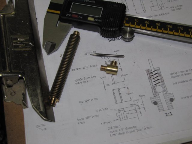
Results of this evening's work; the piece of threaded brass rod on the lower left is the source for nearly all the brass pieces I've been machining up the last couple of days...
Regards, Arnold
I think I'm building up a bullfrog colonyWe all have a wart or two in the shop, you know.
Some work on the regulator this evening...
First up some more bits of brass turned & threaded to make the regulator body. Ready to solder on the pipe connection piece on the body; I just filed the bit of threaded brass to fit the contour of the main body. The toolmaker's clamp is showing what frequent use on the firebrick, combined with regular rainy days is doing to it...
And done... I think my silver soldering is slowly improving:
Next up, the valve spindle; some 4mm stainless rod in the collet chuck, turned down to a taper point:
Then it needed to get turned down length-wise for 3mm thread and clearance at the back. I improvised tailstock support using a scrap brass part-off piece with a centered hole (I think this was from my rocking engine's crank!) in the tailstock chuck on the taper on the workpiece; worked a treat:
Results of this evening's work; the piece of threaded brass rod on the lower left is the source for nearly all the brass pieces I've been machining up the last couple of days...
Regards, Arnold
arnoldb
Well-Known Member
- Joined
- Apr 8, 2009
- Messages
- 1,792
- Reaction score
- 12
Thank you very much Ian
A bit more done on the regulator this afternoon after work.
First up, I made the "inner" part of the regulator that the spindle operates in; nothing major; just a convenient piece of 5mm brass threaded rod drilled & tapped part-way for M3 to fit the spindle.
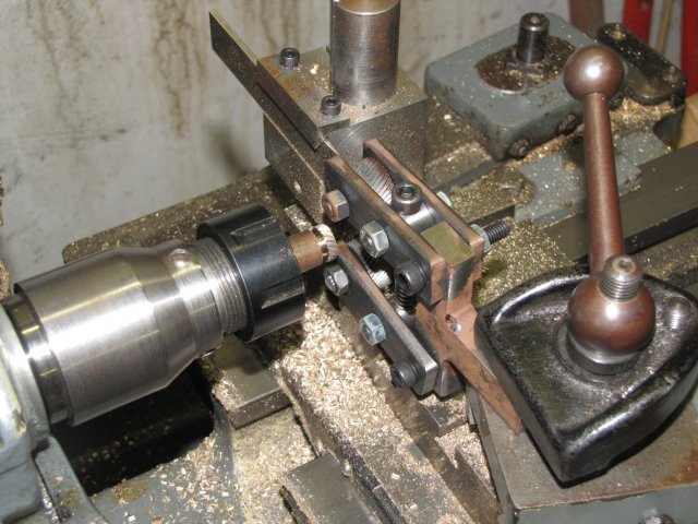
Next up was the packing nut to fit on the outside of the spindle; I don't have suitable hex stock, so the nut had to be made from scratch. Drilled more of my bigger threaded brass rod through at 2.4 mm to complete nut depth, then 4.2mm part-way through that and tapped M5 for the spindle inner mentioned earlier. The outside was then turned down, and then I filed six flats on it to make it into a nut. I couldn't be bothered to set up the lathe for milling the hexagonal flats; I just used the collet chuck nut's tightening grooves and an inside turning tool as both the index marker and basic filing guide:
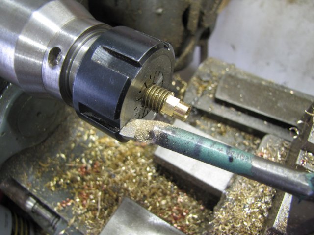
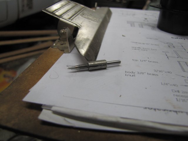
I've been pondering on whether to use a crank arm (like the original plans show) or a wheel to operate the regulator. Made my final choice, and it will be a wheel, so the valve spindle needs a way to mount the wheel and a retaining nut. I'm not about to go about making flats and a square hole with 2mm sides yet, so the wheel will be threaded and a lock-nut used. This meant I need a section of M2 thread on the end of the valve. No problem; just shove it in the 3-2mm ER collet and add the thread... Unfortunately not that easy; the ER collet's grip depth was too deep, so I'd have to grip on the spindle threads... - no go. I made a quick and dirty split collet from 5mm aluminium rod; first used a junior hacksaw to saw it down length-wise, then in the collet chuck and drilled for a close fit in the spindle shaft. Sawed off just behind the longitudinal split and with spindle shoved in, it came to this:
(Sorry; photo's a bit darkish)
Then mounted the lot back in the collet chuck, with the aluminium split collet's non-split part sticking out slightly, so that the ER collet can clamp down on the split only:
That worked a treat; I just turned down the end of the spindle to 2mm and used the tailstock die holder to thread it M2.
A trial assembly; starting to look more like a regulator:
At this point, a pink "glow" invaded my workshop; an indication of a beautiful Namibian sunset outside, as well as time for a drink and making dinner, so I closed shop and started on the rest :

More tomorrow....
Regards, Arnold
A bit more done on the regulator this afternoon after work.
First up, I made the "inner" part of the regulator that the spindle operates in; nothing major; just a convenient piece of 5mm brass threaded rod drilled & tapped part-way for M3 to fit the spindle.
Next up was the packing nut to fit on the outside of the spindle; I don't have suitable hex stock, so the nut had to be made from scratch. Drilled more of my bigger threaded brass rod through at 2.4 mm to complete nut depth, then 4.2mm part-way through that and tapped M5 for the spindle inner mentioned earlier. The outside was then turned down, and then I filed six flats on it to make it into a nut. I couldn't be bothered to set up the lathe for milling the hexagonal flats; I just used the collet chuck nut's tightening grooves and an inside turning tool as both the index marker and basic filing guide:
I've been pondering on whether to use a crank arm (like the original plans show) or a wheel to operate the regulator. Made my final choice, and it will be a wheel, so the valve spindle needs a way to mount the wheel and a retaining nut. I'm not about to go about making flats and a square hole with 2mm sides yet, so the wheel will be threaded and a lock-nut used. This meant I need a section of M2 thread on the end of the valve. No problem; just shove it in the 3-2mm ER collet and add the thread... Unfortunately not that easy; the ER collet's grip depth was too deep, so I'd have to grip on the spindle threads... - no go. I made a quick and dirty split collet from 5mm aluminium rod; first used a junior hacksaw to saw it down length-wise, then in the collet chuck and drilled for a close fit in the spindle shaft. Sawed off just behind the longitudinal split and with spindle shoved in, it came to this:
(Sorry; photo's a bit darkish)
Then mounted the lot back in the collet chuck, with the aluminium split collet's non-split part sticking out slightly, so that the ER collet can clamp down on the split only:
That worked a treat; I just turned down the end of the spindle to 2mm and used the tailstock die holder to thread it M2.
A trial assembly; starting to look more like a regulator
:
At this point, a pink "glow" invaded my workshop; an indication of a beautiful Namibian sunset outside, as well as time for a drink and making dinner, so I closed shop and started on the rest
:
More tomorrow....
Regards, Arnold
arnoldb said:Thank you Dean ;DI think I'm building up a bullfrog colony
No worries, Arnold. I hear croaking noises every time I walk past the door of the shop. Pretty sure it's normal.
At least you know we're all brothers in this stuff.
Nice shots of your continuing work. I use a similar way of making a split collet for holding off sized work or tiny bits. A handy work holding solution.
Keep up the good work!
Ribbitt..
Dean
arnoldb
Well-Known Member
- Joined
- Apr 8, 2009
- Messages
- 1,792
- Reaction score
- 12
Chuck, Thank you - So far it's not that difficult for me; plus I'm learning a lot in the process. Just plain Fun!
Thank you Dean :big: - Ribbit! *beer*
My morning shop time was interrupted by a recalcitrant server at work - took a good bite out of my fun.
Some done though - including another minor booboo.
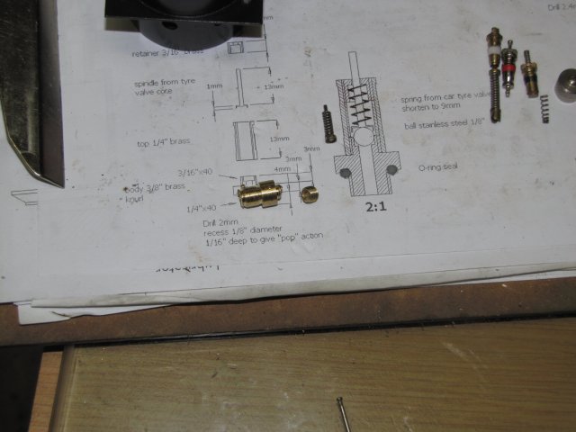
A quick visit to a tire fitment center produced a bag full of tire valves that would normally just be thrown away. Goodie; a freebie!. The staff there were so helpful, that they actually started unscrewing the valves from the stems, but I asked them for stems & all; the stems are nice little brass pipes hidden inside a lot of rubber. It appears that tire valve technology is changing; the type with the long spring favoured by modelers are disappearing.
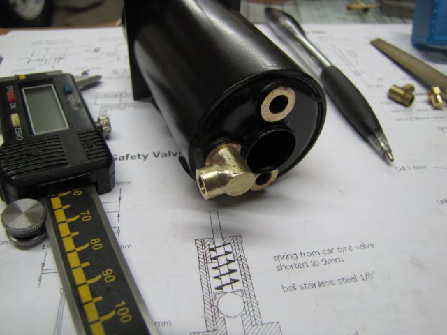
Here is a collection with three different types I found; the one on the left is the one I wanted a lot of, but only a couple surfaced. The one in the middle appears to be the standard used now, with the one on the right another different design, with a very small spring fit to the top of the pin. I'd like a couple more of those as well; those small springs can be handy.
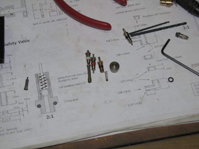
Oh yes, in case you're wondering why I wanted the valves; it's for bits to make the safety valve for the boiler. The valve cap also came in handy!
I marked, drilled, tapped and loctited in the 2mm boiler mounting studs on the frames:
Then I improvised a water filler adapter and cap from some of the tire valves; removed the rubber from one and turned & threaded it to fit the boiler. I got some "shiny" metal valve caps as part of the haul; a bit of emery and the shiny coating (most likely nickel plating) was gone, and the cap is brass. Didn't take a photo of this though.
Next up was the safety valve; I proceeded to build a booboo on the bottom bit for it; I first turned & threaded the one side M5 with a 2mm through-hole, then, using a bit of rod with an M5 threaded hole in the chuck, screwed it in to do the other side. That had to be threaded M6. Too much torque, and it broke on the M5 side.oh: Lesson learnt; try and do the big threads first on a piece like this:
So I restarted the safety valve bottom, big threads first, and took a bit of practice at using the lathe like a shaper to cut gripping grooves on it:
I was surprised how easy this was; back& forth with the carriage with a 2 thou infeed for each pass until each groove was 0.5mm deep.
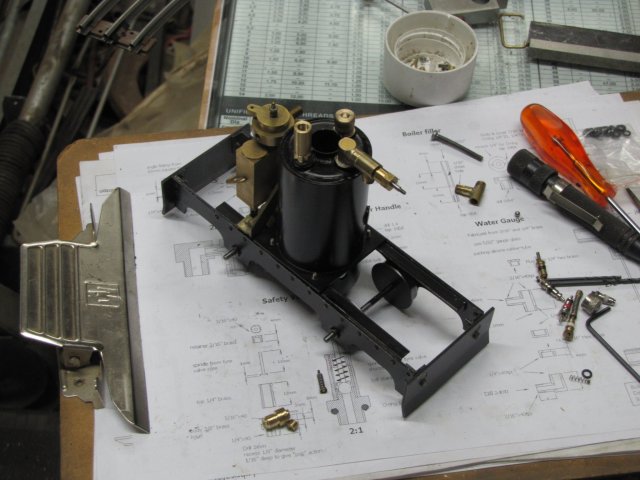
Today's bits were all fit to the boiler, with some ptfe tape to seal the threads; I also assembled the regulator completely ; just the handwheel need to be made & installed on it. I'm not too happy with the tire cap filler; it does not "look" right, so I'll most likely re-make the filler to look like the safety valve:
Hopefully I'll have a better day tomorrow!
Regards, Arnold
- So far it's not that difficult for me; plus I'm learning a lot in the process. Just plain Fun!Thank you Dean :big: - Ribbit! *beer*
My morning shop time was interrupted by a recalcitrant server at work
- took a good bite out of my fun.Some done though - including another minor booboo.
A quick visit to a tire fitment center produced a bag full of tire valves that would normally just be thrown away. Goodie; a freebie!. The staff there were so helpful, that they actually started unscrewing the valves from the stems, but I asked them for stems & all; the stems are nice little brass pipes hidden inside a lot of rubber. It appears that tire valve technology is changing; the type with the long spring favoured by modelers are disappearing.
Here is a collection with three different types I found; the one on the left is the one I wanted a lot of, but only a couple surfaced. The one in the middle appears to be the standard used now, with the one on the right another different design, with a very small spring fit to the top of the pin. I'd like a couple more of those as well; those small springs can be handy.
Oh yes, in case you're wondering why I wanted the valves; it's for bits to make the safety valve for the boiler. The valve cap also came in handy!
I marked, drilled, tapped and loctited in the 2mm boiler mounting studs on the frames:
Then I improvised a water filler adapter and cap from some of the tire valves; removed the rubber from one and turned & threaded it to fit the boiler. I got some "shiny" metal valve caps as part of the haul; a bit of emery and the shiny coating (most likely nickel plating) was gone, and the cap is brass. Didn't take a photo of this though.
Next up was the safety valve; I proceeded to build a booboo on the bottom bit for it; I first turned & threaded the one side M5 with a 2mm through-hole, then, using a bit of rod with an M5 threaded hole in the chuck, screwed it in to do the other side. That had to be threaded M6. Too much torque, and it broke on the M5 side.
oh: Lesson learnt; try and do the big threads first on a piece like this:
So I restarted the safety valve bottom, big threads first, and took a bit of practice at using the lathe like a shaper to cut gripping grooves on it:
I was surprised how easy this was; back& forth with the carriage with a 2 thou infeed for each pass until each groove was 0.5mm deep.
Today's bits were all fit to the boiler, with some ptfe tape to seal the threads; I also assembled the regulator completely ; just the handwheel need to be made & installed on it. I'm not too happy with the tire cap filler; it does not "look" right, so I'll most likely re-make the filler to look like the safety valve:
Hopefully I'll have a better day tomorrow!
Regards, Arnold
zeeprogrammer
Well-Known Member
- Joined
- Mar 14, 2009
- Messages
- 3,362
- Reaction score
- 13
This is a great thread. I am really enjoying this build and learning much.
And the sunset pic was a great bonus. Beautiful.
And the sunset pic was a great bonus. Beautiful.
arnoldb
Well-Known Member
- Joined
- Apr 8, 2009
- Messages
- 1,792
- Reaction score
- 12
Thank you very much Dean ;D - You're lucky, all my booboos take time, material and effort to "engineer" :big:
Zee, thank you ;D - I hope you're learning something useful though; the booboos are not good to replicate; but I'm sure you are aware of that. And the "bonus" pic was a pleasure; that's the kind of thing that makes me put up with some difficulties in obtaining tools & materials rather than emigrating
Thanks very much for the compliment Jim ;D ; you caught me while busy posting the next update
Fred's build is now at an awkward stage; lots of fiddly bits that just plain takes a lot of time to do. Spent a lot of time today filing hex pieces on nuts; wish I had a milling machine!. I completed the safety valve, water gauge, regulator handwheel and chimney. Didn't take a lot of photos though.
Completed the water gauge first; made two nuts, and used some ptfe plumber's tape rubbed into strings to make the seals around the glass. for the top plug, I used a bit of 5mm brass threaded rod off-cut that had a 3mm hole in the end. A cheap 3mm allen socket, with the end touched to the bench grinder to leave sharp edges, threaded rod screwed into an M5 nut, and a whack with a hammer; made an instant hex-drive plug - no photo of the part, but visible in last photo of this post.
Hand wheel rim knurled:
I didn't apply an oil coating to the knurling tool after I made it, so it rusted like mad with our recent good rains. Tooling clean-up for later!
I also faced the one side of the wheel a bit hollow, then threaded it M2 before parting off. Screwed it on the regulator spindle, with some loctite, and an m2 retaining nut.
Getting ready to solder the chimney; I used a piece of copper pipe the same size as the boiler flue for the body, with another piece of the same pipe that I just snipped a longitudinal strip out of with tin snips for the adapter piece; leaving a wide-enough gap for passing over the exhaust tube. The top (which is in the bottom on the photo, is a crimp-on brass ferrule like was mentioned earlier in the thread; in this case used for looks rather than function:
Some cleaning, and painting followed, then some time in the oven; I used the same high temp black paint on it as on the rest of the loco.
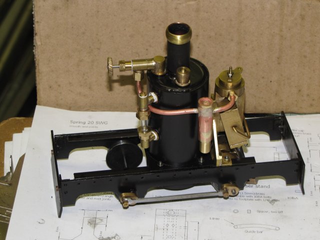
Finally, the loco as it stands this evening. The wire is to get an idea of the length, and curves needed for the steam supply pipe to the engine; I might have to build a pipe bender, as some curves are a bit tight:
I hope to get enough done through the week and next weekend to try a steam test by next Sunday!
Regards, Arnold
Zee, thank you ;D - I hope you're learning something useful though; the booboos are not good to replicate; but I'm sure you are aware of that
. And the "bonus" pic was a pleasure; that's the kind of thing that makes me put up with some difficulties in obtaining tools & materials rather than emigrating Thanks very much for the compliment Jim ;D ; you caught me while busy posting the next update
Fred's build is now at an awkward stage; lots of fiddly bits that just plain takes a lot of time to do. Spent a lot of time today filing hex pieces on nuts; wish I had a milling machine!. I completed the safety valve, water gauge, regulator handwheel and chimney. Didn't take a lot of photos though.
Completed the water gauge first; made two nuts, and used some ptfe plumber's tape rubbed into strings to make the seals around the glass. for the top plug, I used a bit of 5mm brass threaded rod off-cut that had a 3mm hole in the end. A cheap 3mm allen socket, with the end touched to the bench grinder to leave sharp edges, threaded rod screwed into an M5 nut, and a whack with a hammer; made an instant hex-drive plug
- no photo of the part, but visible in last photo of this post.Hand wheel rim knurled:
I didn't apply an oil coating to the knurling tool after I made it, so it rusted like mad with our recent good rains. Tooling clean-up for later!
I also faced the one side of the wheel a bit hollow, then threaded it M2 before parting off. Screwed it on the regulator spindle, with some loctite, and an m2 retaining nut.
Getting ready to solder the chimney; I used a piece of copper pipe the same size as the boiler flue for the body, with another piece of the same pipe that I just snipped a longitudinal strip out of with tin snips for the adapter piece; leaving a wide-enough gap for passing over the exhaust tube. The top (which is in the bottom on the photo, is a crimp-on brass ferrule like was mentioned earlier in the thread; in this case used for looks rather than function:
Some cleaning, and painting followed, then some time in the oven; I used the same high temp black paint on it as on the rest of the loco.
Finally, the loco as it stands this evening. The wire is to get an idea of the length, and curves needed for the steam supply pipe to the engine; I might have to build a pipe bender, as some curves are a bit tight:
I hope to get enough done through the week and next weekend to try a steam test by next Sunday!
Regards, Arnold
arnoldb
Well-Known Member
- Joined
- Apr 8, 2009
- Messages
- 1,792
- Reaction score
- 12
Thank you very much indeed gbritnel
I nipped in a bit of shop time after work and started on the lubricator.
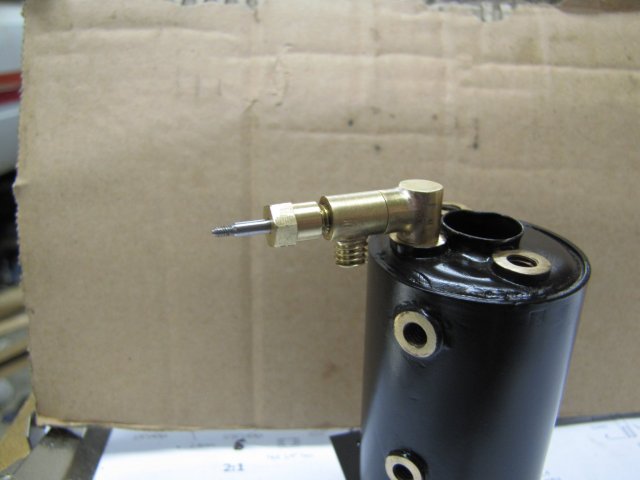
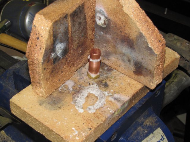
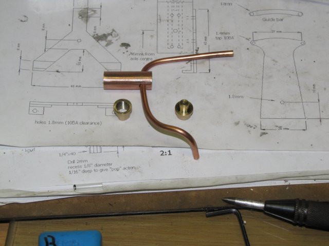
The body is from a bit of "chromed" copper pipe like used from water pipes in walls to wash basins and so on. I removed the shiny coating down to bare copper with sandpaper. Then I turned up a brass bush threaded M8 for the filler cap, as well as the bottom piece - which I forgot to thread M5 before removing from the lathe. An experiment with bending the copper pipe I have, and no sign of collapse or flattening while bending ;D. The bits and bobs made today:
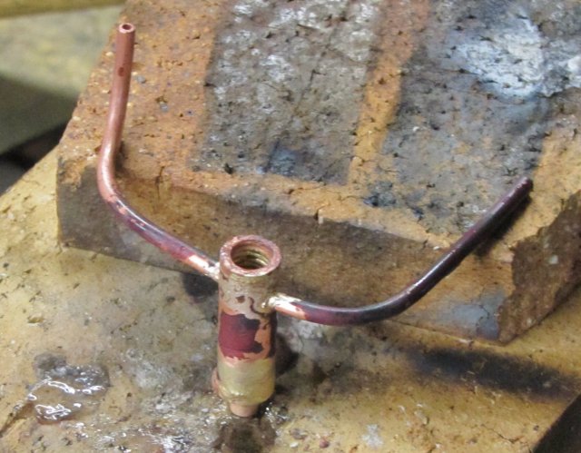
And soldered together:
That lot is spending the night in the pickle; hopefully I can finish off the lubricator tomorrow evening; it needs a filler cap, and the bottom drain valve, and cosmetic work.
Regards, Arnold
I nipped in a bit of shop time after work and started on the lubricator.
The body is from a bit of "chromed" copper pipe like used from water pipes in walls to wash basins and so on. I removed the shiny coating down to bare copper with sandpaper. Then I turned up a brass bush threaded M8 for the filler cap, as well as the bottom piece - which I forgot to thread M5 before removing from the lathe. An experiment with bending the copper pipe I have, and no sign of collapse or flattening while bending ;D. The bits and bobs made today:
And soldered together:
That lot is spending the night in the pickle; hopefully I can finish off the lubricator tomorrow evening; it needs a filler cap, and the bottom drain valve, and cosmetic work.
Regards, Arnold
- Joined
- Aug 25, 2007
- Messages
- 3,890
- Reaction score
- 715
Dang it, between you and Shred, I'm beginning to think a small engine & boiler mounted on wheels going around on a track would be a pretty neat accomplishment. Where am I going to find the time? :-\
Chuck
Chuck
arnoldb
Well-Known Member
- Joined
- Apr 8, 2009
- Messages
- 1,792
- Reaction score
- 12
Thank You Hans ;D - The loco will be run regularly. I have a biggish built-up planter on my porch/entertainment area where I want to put up a railway; a garden layout here in Namibia is a no-go, as the sun would burn the tracks to bits in no time. I will hopefully have the first tracks to lay by end February.
Nick, Thank you! ;D
Chuck, you're a dab hand at machining already; you'll have it done in a flash. I wonder how far your Henry Ford engine can scale down - put that on a chassis with wheels; it would be a hoot to see running!
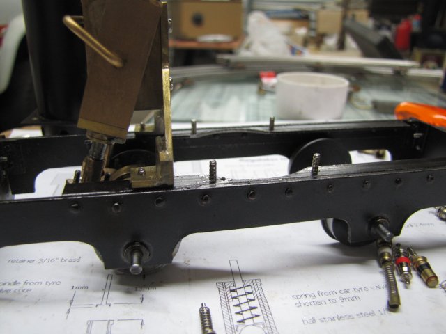
Some more after-work shop time ;D - Cleaned up the lubricator-to-be a bit, and made more nuts. I think I'm nearly done filing round bits into hex shape on this build!. As it is, I made a very good looking nut first time, and when I tested itoh: - made it M5 and not M6! So a spare bit for a future build.
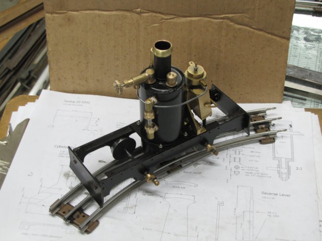
Today's shot; lubricator in position, and main steam pipe bent to near-final shape and shortened to length, with the fitting nuts in place:
The lubricator just needs a cap and the bottom part of it's drain valve, as well as the actual oil hole drilled in the piece of main pipe running through it. I actually started on the rest of the valve, but when cross-drilling for the operating handle, "SNAP" - my only 2mm drill bit is a goner. So I stopped there for tonight; need a couple of new 2mm drills!
The steam pipe also need to have olives silver soldered to either end.
Regards, Arnold
Nick, Thank you! ;D
Chuck, you're a dab hand at machining already; you'll have it done in a flash. I wonder how far your Henry Ford engine can scale down - put that on a chassis with wheels; it would be a hoot to see running!
Some more after-work shop time ;D - Cleaned up the lubricator-to-be a bit, and made more nuts. I think I'm nearly done filing round bits into hex shape on this build!. As it is, I made a very good looking nut first time, and when I tested it
oh: - made it M5 and not M6! So a spare bit for a future build.Today's shot; lubricator in position, and main steam pipe bent to near-final shape and shortened to length, with the fitting nuts in place:
The lubricator just needs a cap and the bottom part of it's drain valve, as well as the actual oil hole drilled in the piece of main pipe running through it. I actually started on the rest of the valve, but when cross-drilling for the operating handle, "SNAP" - my only 2mm drill bit is a goner. So I stopped there for tonight; need a couple of new 2mm drills!
The steam pipe also need to have olives silver soldered to either end.
Regards, Arnold
Coming along nicely Arnold ............ not too long till the inaugural video now ;D
I know you've said before that tooling is a bit awkward to get in your part of the world, how do you go on for things like drill bits, can you get those pretty easily
Good luck, looking forward to the rest ;D
CC
I know you've said before that tooling is a bit awkward to get in your part of the world, how do you go on for things like drill bits, can you get those pretty easily
Good luck, looking forward to the rest ;D
CC