Building Elmer's #46 rotary

Home Model Engine Machinist Forum

Help Support Home Model Engine Machinist Forum:

This site may earn a commission from merchant affiliate links, including eBay, Amazon, and others.
Looks neat with the parts put together, Arnold. Should be very interesting when you have
it completed.
Hope you don't go overboard with the so-called 'bling'. Sometimes it looks sooo... Mr. T! ;D

We have some similar shop habits. Like where you slice off the forks with the slitting saw, leaving
just a whisker holding it. Keeps parts where you can find them!

Dean
 
Arnold,

You sure are moving at a fast pace.

I really like the looks of the #46 engine and am looking forward to seeing it run.

Keep up the good work.

SAM
 
Looking really nice Arnold.

I like the way you made the heads. Well done.
 
Shoot Arnold, give your sister a nice soft cloth and some polish and you both can visit and get the parts all bling-ie at the same time :big: That way it will only take 1/2 the time and you''ll still have next weekend to do final adjustments. :big:

Looks terrific so far and I do so like the studs and nuts route. (the 'proper' way as they say)


BC1
Jim
 
Thanks Dean. No - I don't think the bling will get to Mr T stage :big: - there will be a bit of shiny things, but also some paint, and possibly a "surprise" finish on some bits; I'm still thinking if I want to risk doing that though...

Sam, Thanks! - I'm also looking forward to see it run ;D

Kevin, thanks. I was staring at the drawings, and the thought just popped into my head to make the heads like that. Fortunately on this engine there's no need for pack nuts, so it worked ;D

Thanks Jim. My sister postponed her visit on no 99 - so I guess I'm alone to do the polishing ;D. :big: The old studs 'n nuts... Seems like I'm forced into it anyway with what I have available to me. I'm getting so used to making little brass nuts, I'm considering building a micro threading "combination" lathe that I can take to work and spend my lunchtimes productively Rof}

Well, I'm happy to report that some of the interference problems are gone; I took an hour this afternoon and filed the mounting holes for the thick bearing block on the base away by 0.5mm towards the outer edge of the base. Nobody will see that when the engine is assembled. Except, now EVERYBODY knows I did it :-[.

I also lightly chucked and carefully centered the cylinder block in the 4-jaw on the thin shaft side - protected by a couple of layers of paper wrapped around the shaft to prevent chuck marks. Then I VERY carefully turned more of the shoulder on the valve side down with the rear parting tool to the valve size.

These two operations gave me the necessary clearance needed to remove all of the interference on that side of the cylinder block and _just_ makes the cylinder "float" in the cam. Sorry, no photos today.

I'm still getting a bit of axial interference in the heads as well, but I'll first make the 2mm nuts so I can bolt them down properly before further checks in that area.

Another thing I saw that was causing interference was the height of the spigots on the heads; on the "bottom" of the revolution, the head spigot and the fork back would touch - I solved that by removing another 0.2mm from each of the heads, and that's now clear as well.

Regards, Arnold
 
Having to expand or elongate a hole here and there is standard procedure for handmade craftsmanship I would think, Mr. Arnold. It's what makes it so special. :)

I appreciate all the effort you've put into this thread, I know how much extra work that takes. It sure helps all us Greenies out here.

Video coming before long, huh?

-Trout
 
I had missed this thread up until today. I was a junior member of the TB2 group and have received most of the parts that were produced. They are all sitting in a parts drawer waiting for me to finish and make the few that are missing.

The cam ring was machined beautifully by Gail on his CNC mill. I had thought that the form needed to be somewhat "oval", and that a circle wouldn't work. I can't tell from your pics whether your ring is made that way.

I'm looking forward to seeing your run. Hopefully I'll get around to finishing mine before too many years go by.
 
Hi Arnold,
Didn't see your Jul 4 post till today. Wow. It's really looking good. Can't wait to see it running. Also, very nice write-up. Thanks for posting it.
Dennis
 
Thanks Carl ;D - Problem is I don't think I'll forget :big: - But then again, I don't think anybody on HMEM builds machines that are completely perfect ;D I just don't think it can be done (though gbritnell and some others get pretty darn close!)

Trout, thanks ;D - but I don't know about the "Mr. Arnold" bit... I'm just plain "arnold" - i don't even deserve the "a" in caps, though my English teacher would have a coronary if she saw this grammar :big:. Oh and I'm also just a Greeny - I have a fully paid up membership in mis-made parts and bad swarf! It is hard work sometimes (as well as humiliating ;)) to post a full build thread, but it becomes really worthwhile, as one gets a lot of helpful information in return like I have, as well as just maybe inspiring or helping someone else in their own efforts in the process.

Thanks kvom - It's a real pity that TB2 seems to have fizzled out without a good result. Yes, the cam is oval (elliptic) - and without CNC I used MMC (Manual Machine Control) to cut it earlier on in the build Its not really visible, but it is indeed elliptic.

Thanks very much Dennis ;D - its a pleasure!

Tonight's little bit - I made a couple of 2mm nuts from 3.2mm brazing rod like I've done on past builds (file, drill, thread and part off). Made 9 nuts in case the shop monster wanted one:
normal_IMG_1481.JPG


Then mounted those on the cylinder on the studs, and used a cut-off disc in the Dremel to trim the studs down. Not the ideal use of the Dremel cut-off discs on brazing rod, but it does the job with light cuts at a slightly reduced spindle speed. A bit of a polish where I wanted it - not too much, but things do shine, and this lot is done:
normal_IMG_1482.JPG


I also splurged a bit on some brown stuff today; I bought a bit (2m x 200mm x 25mm - that was the smallest I could find) of Rhodesian Teak. A bit of that will make for a (I hope!) nice wooden base.

Regards, Arnold
 
Arnold,

I almost didn't see the cylinder assembly in your last photo. It was well camouflaged with the polish job. It just blended into the background. Well done. I have thought about building #46, but the eccentric has me intimidated.

Regards,

SAM

 
Sure is looking good, Arnold.
I have been following along with anticipation.
Gail in NM
 
Not a problem, but referring to the cam profile as elliptical might lead someone astray. The Cam profile is not an ellipse or elliptical. I have forgotten what the curve is called, but it looks some what like an egg standing upright on the big end. Just not as pronounced.
Gail in NM
 
Good going, Arnold.
When I first saw that last pic, I thought, "Why did he put pencil marks all over it?".
;D 'Snot pencil marks, silly man! It's in the prints!
All is clear.

Dean
 
Thanks Sam. If you have a rotary table, the eccentric's not difficult - it just takes some time and concentration to do. ::) Believe me, that polish job is far from perfect, but I'll term it "adequate" for this build :)

Gail thank you. You had me somewhat concerned for a moment - but after a re-look at the plans and the data, you are right; the cam is somewhat egg-shaped - very little as you mentioned; and it is difficult to see on the model itself! I just hope it does not go pear shaped for me :big:

Thanks Dean. Now why would I use a pencil there scratch.gif - the silver soldering's done and pencils are NBG in a machine shop except for preventing silver solder to go where it mustn't :big:. HMMM scratch.gif - maybe good for giving graphite-based lubrication as well - draw-on lubrication so to speak... ;D I'm just being facetious :big:

Tonight I finished the flywheel. Pretty much like I did the grasshopper's one from a square bit of 8mm plate turned down using Bogs's methods. I was in two minds as to making it spoked vs leaving it as per plans. As it's not very prominent in the designed location, I decided to leave it "simple", so nothing major for today's update:
normal_IMG_1483.JPG

I did add a bit of paint in the recesses on the flywheel; I'll first see what things look like when assembled before I show that.
I also did a bit of experimenting with finishes as well - more on that later, as some more experimentation is required ;)

Regards, Arnold
 
arnoldb said:
Thanks Dean. Now why would I use a pencil there scratch.gif - the silver soldering's done and pencils are NBG in a machine shop...:big:.

Regards, Arnold

Oh yes they are! Gives you something to nervously chew on when doing those tricky rotary table contortions!

(I know you were kidding. They're good for cleaning out yer ears, too.)

Thanks for the update. ;D

Dean

 
Thanks Dean ;D - I forgot about chewing on pencil ends :big: - Last time I did that was in 1990 in draughting class in school - no CAD back then and a selection of pencils of different hardness for drawing different line types. This was just about the only class in school for which I did homework - I loved drawing the parts! Didn't like the paint that came off then ends though!

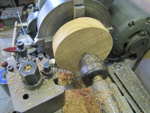
Today I started off with a bit of brown stuff. I'm not particularly fond of woodwork, but can do a "sort of OK" job of it when needed. Just used a jigsaw to hack a squarish bit off the piece of wood I bought earlier this week, drew a circle on it and trimmed off most of the excess outside of the circle with the jigsaw, and stuck it up on the lathe by pressing the revolving tail center into the center of the circle and squeezing it down on the face of the 4-jaw chuck pretty hard. Then with a very sharp HSS toolbit, just turned it down:
normal_IMG_1484.JPG


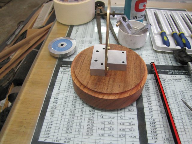
After some more turning, and then a bit of sanding followed by some floor/furniture wax, the wood base was good to go, so I marked the mounting hole locations using the engine base itself as a jig:
normal_IMG_1485.JPG

After drilling pilot holes for some brass wood screws, I sanded the wood base down again, and then coated it thickly with more of the wax and set it in the sun so the wax could melt a bit and seep into the wood.

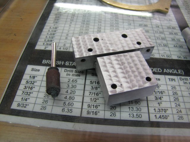
Earlier on this week I did some experimentation on the "stuffed" base I made right at the start. I've never done engine turning, and was toying with the idea of doing some on the base. I tried a couple of different methods; from wood dowels coated with grinding paste to sticking some emery on the tip of some 6mm rod; nothing worked particularly well though. I finally hit on cutting a bit of Scotch-Brite off a pad, and using a small drum sander from my Dremel's kit with a worn-out sanding drum as retainer - with a "pocket" left on the bottom to shove the bit of Scotch-Brite in. This worked OK, so while the wood base was languishing in the sun, I did the engine turning on the drill press. The cross-vice was a boon here, as it was easy to get each "touch" in a symmetric pattern. So this is what it came out like; not perfect, but I'm happy with it for now:
normal_IMG_1486.JPG


After that followed a bit of clean-up of all the parts and a finicky assembly. It's easier to first mount the cylinder in the cam, then slip on the thick bearing/valve block, and then drop the lot on the base and first bolt down the cam and then the bearing block. I'd already soldered the one fork to the connecting rod as per Elmer's instructions at this point. Then slip on the flywheel, and the last bearing block and screw & bolt those down. As a final operation, shift the last fork out and solder that to the con rod. I turned the engine, and had quite a bit of binding...
I traced some binding down to a "tight" spot on the cam; I just used a small half-round file to file down those bits, followed by some 320 grit emery. Thes left a tight spot when the connecting rod was nearly vertical - caused by a tiny excess bit of solder on the forks, so I patiently filed that down as well with some needle files.

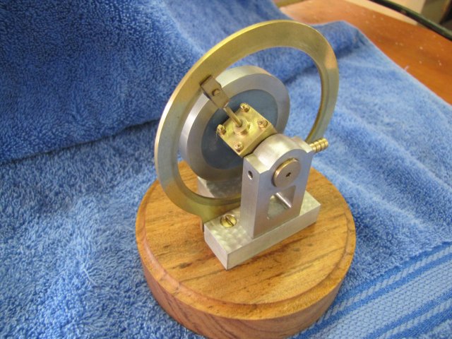
Then I gave everything a liberal dose of oil all over the running surfaces, and put it on the compressor for a bit of a run-in. Initially the engine was very stiff and required up to 40psi to start and keep on running. After about 20 minutes with a couple of stops for more oil, it got down to running at about 15 psi. Then I stripped the lot, cleaned all the dirty run-in oil off, and re-assembled with clean oil.
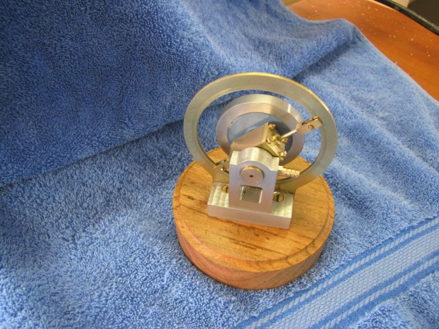
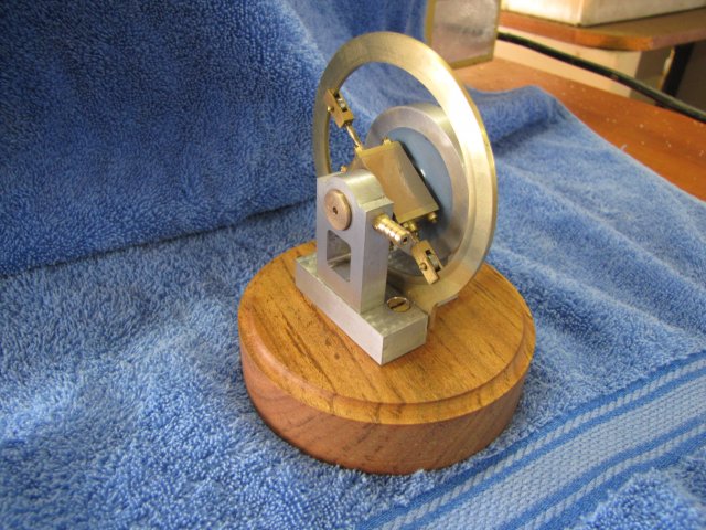
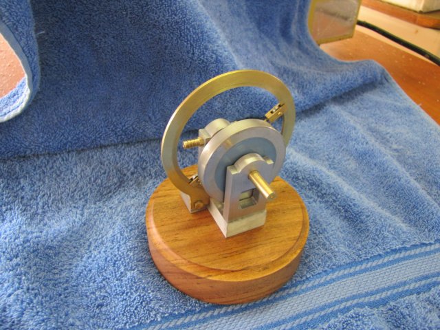
The result:
normal_IMG_1488.JPG

normal_IMG_1489.JPG

normal_IMG_1490.JPG

normal_IMG_1491.JPG


And the video - ::) poorly made once again... :
[ame]http://www.youtube.com/watch?v=NBxAIfydmIQ[/ame]

This was a challenging, but fun, little engine to build; I certainly made more goof-ups on it than any of my other builds. That is completely negated by seeing the little bugger run though; it is extremely interesting to watch ;D ;D ;D

Many Many thanks to everyone who has followed along on this build and provided technical and moral input - It's a pleasure and privilege to share with you guys!

Kind regards, Arnold

Time for a *beer* ;D
 
Congratulations, Arnold! :bow:

Another excellent running engine for your collection.

Well done.

It's amazing how slow it does run for such an awkward seeming arrangement of mechanisms.
 
You've done a great job Arnold. Again!
What an interesting engine. Well done!

Dean
 
Back
Top