
You are using an out of date browser. It may not display this or other websites correctly.
You should upgrade or use an alternative browser.
You should upgrade or use an alternative browser.
Building Elmer's #46 rotary
- Thread starter arnoldb
- Start date


Help Support Home Model Engine Machinist Forum:
This site may earn a commission from merchant affiliate
links, including eBay, Amazon, and others.
- Joined
- Aug 8, 2009
- Messages
- 930
- Reaction score
- 12
Those bearing blocks look very stately Arnold. This is shaping up to be a masterpiece.
I can't believe how much I like using my cheap DRO's now. It is so worth the effort and money. Zee, it's not too late to jump on the bandwagon! ;D
-T
I can't believe how much I like using my cheap DRO's now. It is so worth the effort and money. Zee, it's not too late to jump on the bandwagon! ;D
-T
mklotz
Well-Known Member
Rather than making two or more passes with a slitting saw, I buy them in aliquot sizes and stack them to make the kerf width I need. Works nicely and the saw doesn't try to "hunt" into an already made slot.
arnoldb
Well-Known Member
- Joined
- Apr 8, 2009
- Messages
- 1,792
- Reaction score
- 12
Thanks Carl. Yeah - I love the mill ;D; still some issues to sort out on it though; I think the spindle bearings are still not pre-loaded enough. And a 3-axis DRO... I can't possibly afford that for the foreseeable future, but I have a hare-brained idea that does not involve digital calipers...
Dean, thanks! - I'm happy to know that others do it as well ;D.
Thank you Jim. Rounding them over on the RT would work as well, but then I don't get the sharpish bottom edges without lots of setup and changing positions... I've been contemplating making a dedicated profile cutter for the "Elmer" bearing blocks; but I'm just plain too lazy :big:
Thanks Kevin. All the rounding over by hand; my little files are my friends ;D And after filing, a bit of effort with emery as well. Fortunately Tel gave me the hint about using oil on the sand paper; that works a treat if you're not scared of getting your fingers VERY dirty")
Trout, thanks; I don't know about a masterpiece though... Wait till you see today's trials and tribulations :-[
Thanks Marv. I have the same idea about the slitting saws; All the ones I have (that is BOTH of them) was bought with stacking them in mind, and my arbor made to accommodate that. I did not take the tooth count into consideration though :-[. On materials that does not clog up the teeth, stacking them works very well, but with the teeth not matching, aluminium clogs the tooth spaces up very quickly; no matter what I try to use as lubrication.
Well, today I made the cam ;D... TWICE At least My RT did it's part properly ;D
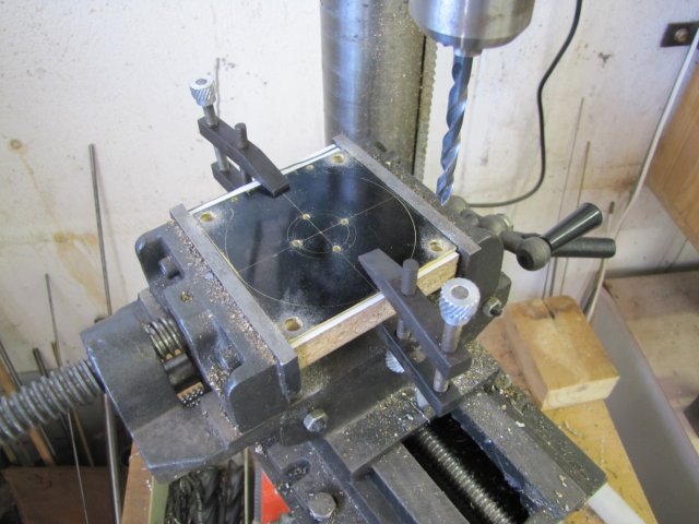
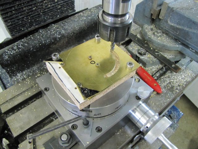
To mount the workpiece, I had to have backing for it (NO WAYS am I going to mill into the RT!). A block of brown stuff left over from when I re-did my kitchen a while ago came in handy, and I clamped the brass plate to it, and then drilled some holes on the drill press. Some small holes for putting screws in to hold the center down as that would be completely separated from the outside piece, as well as four mounting holes to bolt the lot to the RT and retain the outside ring in the process:
I've read some scathingly bad reviews of these cross-slide vises - and they are not great, but mine is invaluable on the drill press!
Can anybody spot the error yet?
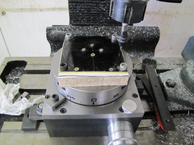
The only way I could mount and clamp this lot on the RT was to have it offset at 45 degrees so I could line up the bigger (7mm to leave room for adjusting on 6mm bolts) holes I drilled with the T-slots on the table. I think my RT is too small... With the offset, the entire set of calculations was worthless, so I had a couple of choices - 1. Add the offset to the calculations in the spreadsheet and re-print the page. 2. Physically turn the RT base to 45 degrees on the mill table to eliminate the offset. 3 - and what I did; save a tree by not printing another page, and put temporary degree markings on the RT table with a marker pen - no need to offset the RT base. The RT was already clamped, and I had centered it properly to the mill spindle; Y was locked down, and my "DRO" was reset to zero as well. So I set the workpiece on center as accurately as possible using a 1mm center drill as reference - I really need to find (or make) a wiggler set for these operations!. With the workpiece properly (or so I thought) centered, I cranked X out to check on the square line for "rotational" alignment; pretty close, so I rotated the RT the necessary amount to get it spot on, and set the adjustable collar to zero on the RT. Good to go:
What?, you didn't spot the mistake yet ? - Neither did I!
I decided to use a new 6mm multi-flute end mill to cut the cam. 6mm, as that is what the engine's rollers will be (instead of 1/4"). Multi-flute, as I have discovered that these make MUCH nicer cuts than 2-flute. If you look at the bearing blocks in an earlier post, you'll see the difference in finish between the rectangular cut-outs on the thin and thick bearing blocks. The thin one was done with a 2-flute slot mill, and I had to do a lot of filing to clean it up. The thick one was done with the multi-flute (4mm in that case) as my 2-flute 4mm was too short to do the job. Surprise! - It did a much nicer job. My multi-flutes are not center cutting, so I needed a starter hole, which I just drilled with a 6mm drill, but at a 0.5 mm closer "radius" setting than the milling cutter would take - to give the milling cutter it's center clearance. Then I started cutting; 2 degree turn on the RT, and the reading from the table dialed in on X, and feed Z. Repeat. Repeat another 43 times. 1/4 way there and I took a smoke break:
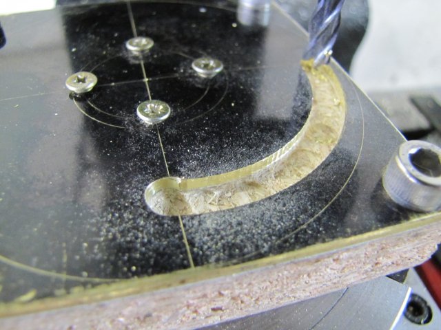
Something seemed odd, but I just could not place my finger on it though... - I was in "feed the angle, turn the X, feed Z mode. Lots of readings to keep track of; "nothing will distract me..." (well, except a smoke break :big
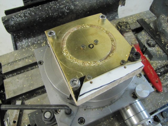
Once I finished the the entire 360 degree circle; that is 180 Z cuts with X adjusted on each, JOY ;D - I'm done ;D ;D. Not a single mis-feed or booboo ;D:
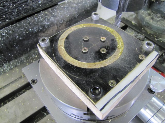
Stand back and admire a bit ;D.....oh: oh: :wall: :fan: - Yup; it hit me... When I set up the workpiece, I used the cam outer ring center instead of the bearing axis center to align the workpiece :-[ RATS, DRAT, DARN, WTFWYT... My brass plate is valuable (not only because of price; it's VERY hard to find.
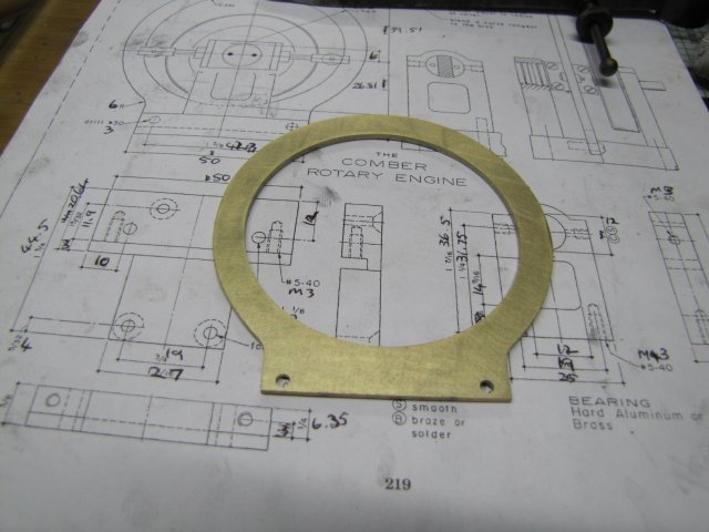
I had a couple of ideas on making a rescue, but none would suffice, so I started again, and finished the job properly (I hope!):
I trimmed most of the excess off the cam ring (some bandsawing), and filed it down roughly to size based on the lines I scribed for the outside profile. The cusps left from milling on the inside of the cam was also filed down lightly till they were all just about gone; some more work needed with emery to clean those up. Then I stopped for the day; I wanted the cam finished today, but, alas, that was not to be.
Shot of the roughly finished cam:
And an assembly shot:
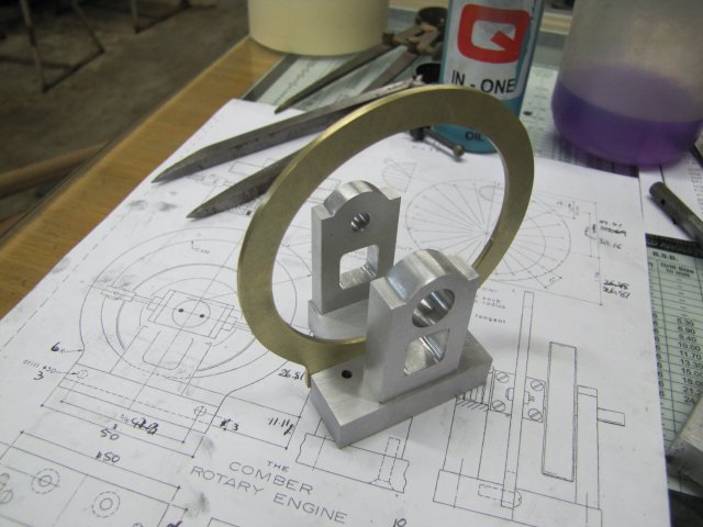
You can see where the cam meets the base that some more filing is needed! At least, its starting to look like something... Some more work needed...
Regards, Arnold
Dean, thanks! - I'm happy to know that others do it as well ;D.
Thank you Jim. Rounding them over on the RT would work as well, but then I don't get the sharpish bottom edges without lots of setup and changing positions... I've been contemplating making a dedicated profile cutter for the "Elmer" bearing blocks; but I'm just plain too lazy :big:
Thanks Kevin. All the rounding over by hand; my little files are my friends ;D And after filing, a bit of effort with emery as well. Fortunately Tel gave me the hint about using oil on the sand paper; that works a treat if you're not scared of getting your fingers VERY dirty
Trout, thanks; I don't know about a masterpiece though... Wait till you see today's trials and tribulations :-[
Thanks Marv. I have the same idea about the slitting saws; All the ones I have (that is BOTH of them
) was bought with stacking them in mind, and my arbor made to accommodate that. I did not take the tooth count into consideration though :-[. On materials that does not clog up the teeth, stacking them works very well, but with the teeth not matching, aluminium clogs the tooth spaces up very quickly; no matter what I try to use as lubrication.Well, today I made the cam ;D... TWICE
At least My RT did it's part properly ;DTo mount the workpiece, I had to have backing for it (NO WAYS am I going to mill into the RT!). A block of brown stuff left over from when I re-did my kitchen a while ago came in handy, and I clamped the brass plate to it, and then drilled some holes on the drill press. Some small holes for putting screws in to hold the center down as that would be completely separated from the outside piece, as well as four mounting holes to bolt the lot to the RT and retain the outside ring in the process:
I've read some scathingly bad reviews of these cross-slide vises - and they are not great, but mine is invaluable on the drill press!
Can anybody spot the error yet?
The only way I could mount and clamp this lot on the RT was to have it offset at 45 degrees so I could line up the bigger (7mm to leave room for adjusting on 6mm bolts) holes I drilled with the T-slots on the table. I think my RT is too small... With the offset, the entire set of calculations was worthless, so I had a couple of choices - 1. Add the offset to the calculations in the spreadsheet and re-print the page. 2. Physically turn the RT base to 45 degrees on the mill table to eliminate the offset. 3 - and what I did; save a tree by not printing another page, and put temporary degree markings on the RT table with a marker pen - no need to offset the RT base. The RT was already clamped, and I had centered it properly to the mill spindle; Y was locked down, and my "DRO" was reset to zero as well. So I set the workpiece on center as accurately as possible using a 1mm center drill as reference - I really need to find (or make) a wiggler set for these operations!. With the workpiece properly (or so I thought) centered, I cranked X out to check on the square line for "rotational" alignment; pretty close, so I rotated the RT the necessary amount to get it spot on, and set the adjustable collar to zero on the RT. Good to go:
What?, you didn't spot the mistake yet ? - Neither did I!
I decided to use a new 6mm multi-flute end mill to cut the cam. 6mm, as that is what the engine's rollers will be (instead of 1/4"). Multi-flute, as I have discovered that these make MUCH nicer cuts than 2-flute. If you look at the bearing blocks in an earlier post, you'll see the difference in finish between the rectangular cut-outs on the thin and thick bearing blocks. The thin one was done with a 2-flute slot mill, and I had to do a lot of filing to clean it up. The thick one was done with the multi-flute (4mm in that case) as my 2-flute 4mm was too short to do the job. Surprise! - It did a much nicer job. My multi-flutes are not center cutting, so I needed a starter hole, which I just drilled with a 6mm drill, but at a 0.5 mm closer "radius" setting than the milling cutter would take - to give the milling cutter it's center clearance. Then I started cutting; 2 degree turn on the RT, and the reading from the table dialed in on X, and feed Z. Repeat. Repeat another 43 times. 1/4 way there and I took a smoke break:
Something seemed odd, but I just could not place my finger on it though... - I was in "feed the angle, turn the X, feed Z mode. Lots of readings to keep track of; "nothing will distract me..." (well, except a smoke break :big
Once I finished the the entire 360 degree circle; that is 180 Z cuts with X adjusted on each, JOY ;D - I'm done ;D ;D. Not a single mis-feed or booboo ;D:
Stand back and admire a bit ;D.....
oh: oh: :wall: :fan: - Yup; it hit me... When I set up the workpiece, I used the cam outer ring center instead of the bearing axis center to align the workpiece :-[ RATS, DRAT, DARN, WTFWYT... My brass plate is valuable (not only because of price; it's VERY hard to find. I had a couple of ideas on making a rescue, but none would suffice, so I started again, and finished the job properly (I hope!):
I trimmed most of the excess off the cam ring (some bandsawing), and filed it down roughly to size based on the lines I scribed for the outside profile. The cusps left from milling on the inside of the cam was also filed down lightly till they were all just about gone; some more work needed with emery to clean those up. Then I stopped for the day; I wanted the cam finished today, but, alas, that was not to be.
Shot of the roughly finished cam:
And an assembly shot:
You can see where the cam meets the base that some more filing is needed! At least, its starting to look like something... Some more work needed...
Regards, Arnold
That part came out nice, (in the end), Arnold. It's about enough to drive a guy crazy making a mistake on a piece of brass! It's not hard to get here, but quite expensive compared to other metals.
You got it done!
Dean
You got it done!
Dean
zeeprogrammer
Well-Known Member
- Joined
- Mar 14, 2009
- Messages
- 3,362
- Reaction score
- 13
Ah bummer Arnold. If I'd still been smoking...I would have taken a pack of cigs to start again. Very glad it came out well.
arnoldb
Well-Known Member
- Joined
- Apr 8, 2009
- Messages
- 1,792
- Reaction score
- 12
Dean, thanks. Yup; horribly expensive; I can get from South Africa, but by the time I've had to add import duties and transport costs its a right bummer. Thinner sheet I can get locally; I finally found a local engraver that will sell me odd bits without insisting that I have things engraved on it...
Thanks Carl. I guess I'll have to give up the smokes soon though. We have some draconian anti-smoking laws coming into effect here in Namibia soon... Don't know what I'm going to do to take little thinking breaks though :shrug: . Gum's out; I hate the stuff. I guess I'll have to plant celery and chew on the sticks :big:
Yesterday evening was spent on chores & pumping iron (not at the gym - the clothes iron works just as well)
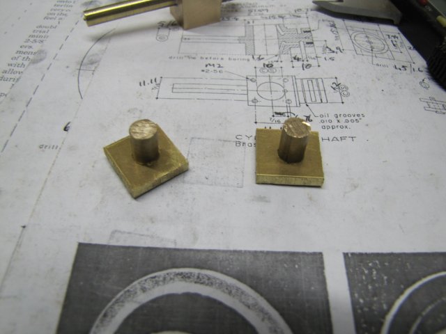
Tonight I cut a block of brass off some 1" square stock I have, faced one cut end square to the sides, and found the center of it and used a center cutting 6mm slot drill to counter bore about 4mm deep on the center. Then I turned some 7mm brass rod down to have a slightly loose bearing fit in the 6mm bearing block (Elmer mentions making this bearing fit slightly "looser" than the other one that that acts as the valve) , and silver soldered (brazed) the two together:
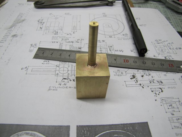
At least its getting easier all the time to do the silver soldering, and the joints are starting to look nicer as well with less clean-up.
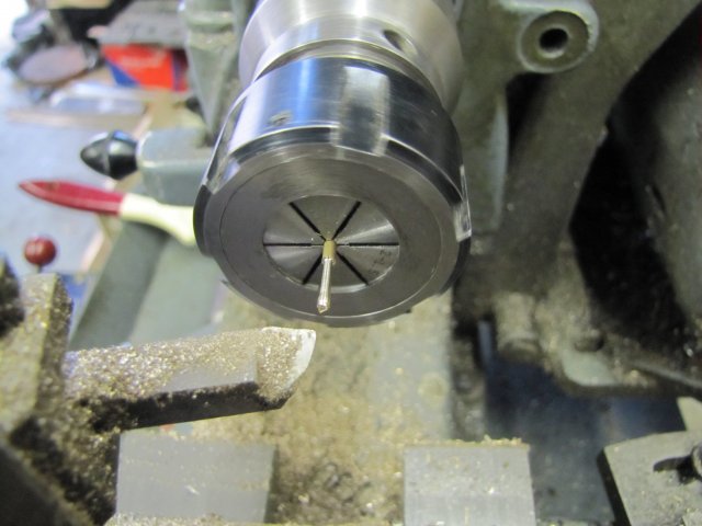
That's the start of the cylinder block. Before I soldered the shaft to the block, I ran through the machining that would be needed to finish the cylinder block, and the shaft would not be in the way and would be very useful to indicate for squareness when boring the cylinder. I know my 6mm collet mounted in the lathe collet chuck runs within 0.005mm true, so I'm going to use that to grip the shaft and center-drill the other end for tailstock support to finish the other bearing/valve face on the block. I think it will work...
Regards, Arnold
Thanks Carl. I guess I'll have to give up the smokes soon though. We have some draconian anti-smoking laws coming into effect here in Namibia soon... Don't know what I'm going to do to take little thinking breaks though :shrug: . Gum's out; I hate the stuff. I guess I'll have to plant celery and chew on the sticks :big:
Yesterday evening was spent on chores & pumping iron (not at the gym - the clothes iron works just as well)
Tonight I cut a block of brass off some 1" square stock I have, faced one cut end square to the sides, and found the center of it and used a center cutting 6mm slot drill to counter bore about 4mm deep on the center. Then I turned some 7mm brass rod down to have a slightly loose bearing fit in the 6mm bearing block (Elmer mentions making this bearing fit slightly "looser" than the other one that that acts as the valve) , and silver soldered (brazed) the two together:
At least its getting easier all the time to do the silver soldering, and the joints are starting to look nicer as well with less clean-up.
That's the start of the cylinder block. Before I soldered the shaft to the block, I ran through the machining that would be needed to finish the cylinder block, and the shaft would not be in the way and would be very useful to indicate for squareness when boring the cylinder. I know my 6mm collet mounted in the lathe collet chuck runs within 0.005mm true, so I'm going to use that to grip the shaft and center-drill the other end for tailstock support to finish the other bearing/valve face on the block. I think it will work...
Regards, Arnold
Arnold, it sounds like you have a good plan for machining your cylinder. Like you, thinking the whole thing
through helps me get things done without too many goofs. (Not too many, at least!)
You iron your clothes? Impressing the ladies, or the boss? ;D
Dean
through helps me get things done without too many goofs. (Not too many, at least!)
You iron your clothes? Impressing the ladies, or the boss? ;D
Dean
vascon2196
Well-Known Member
- Joined
- Oct 2, 2009
- Messages
- 1,026
- Reaction score
- 312
Awesome! Awesome! Awesome!
arnoldb
Well-Known Member
- Joined
- Apr 8, 2009
- Messages
- 1,792
- Reaction score
- 12
Thanks Dean. Thinking the processes through is a bit like playing chess... Opponent's the metal-monster ;D. Don't just take a piece now because you can; it might be a trap! and No, not trying to impress the ladies or the boss; have to set a good example for my young assistant and keep my mom happy ;D Wel,, maybe impress the ladies as well :big:. Boss is easily impressed by just making a "sh1t hot" (as he calls it) Powerpoint presentation on his behalf :
Thanks Chris!
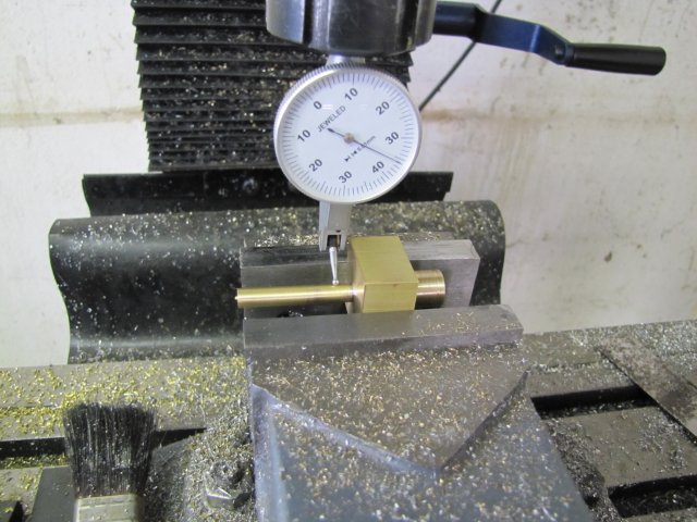
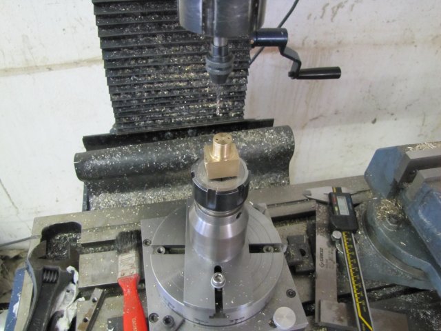
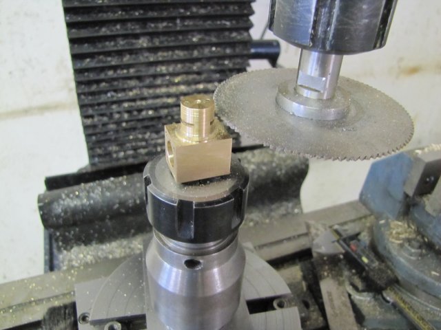
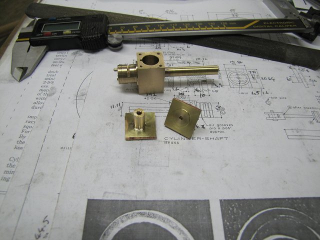
Some progress on the cylinder today. Just chucked the workpiece up on the shaft in the collet chuck, and carefully center-drilled it with a small center drill, so that I could bring up the tailstock for support. Then I carefully checked that I would have enough clearance and angles to turn down the bearing/valve combination. Ended up I had to move the toolbit a bit further out from the toolholder to get the clearances, but nothing major:
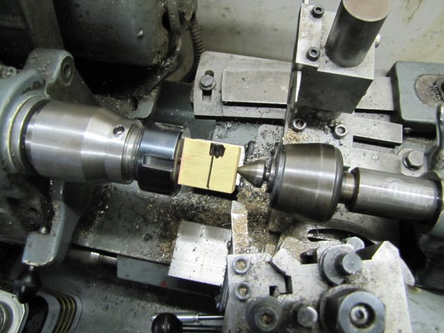
Then I turned it down - first to the size of the step for the entire length, and then further down to size on the bearing surface. When I was about 0.01mm away from final size, I cheated a bit and used a small triangular needle file to file in the two oil grooves (quicker than setting up a threading bit for the job; just be careful to hit the mark square-on and not let slip). There is a third lighter groove - that would be the final length of the bearing surface. For now I left it over length, as the last operation on the piece would be to face it down to that mark; after some holes were drilled and plugged up. As a last operation in the lathe for now, I then extended the piece further out of the collet chuck, and still with tailstock support and a right-hand tool just cleaned up the other face and excess silver solder. Part as done for tonight:
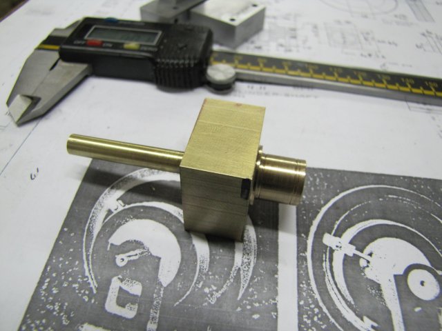
Next its on to the milling machine for it.
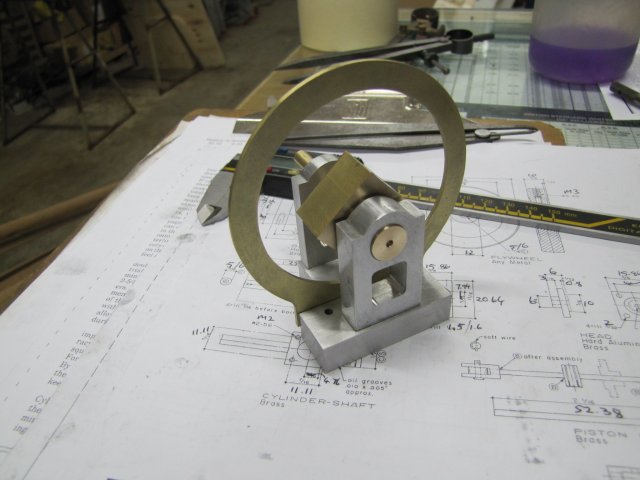
And an assembly shot:
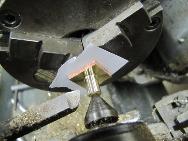
It runs nicely in the bearings with no lateral play at all. There is slight galling when pressed against the thick bearing block; I think that is caused by the sharp corner on the bearing block, so I'll give that a minute chamfer with a piece of sand paper rolled into a cone.
Regards, Arnold
Thanks Chris!
Some progress on the cylinder today. Just chucked the workpiece up on the shaft in the collet chuck, and carefully center-drilled it with a small center drill, so that I could bring up the tailstock for support. Then I carefully checked that I would have enough clearance and angles to turn down the bearing/valve combination. Ended up I had to move the toolbit a bit further out from the toolholder to get the clearances, but nothing major:
Then I turned it down - first to the size of the step for the entire length, and then further down to size on the bearing surface. When I was about 0.01mm away from final size, I cheated a bit and used a small triangular needle file to file in the two oil grooves (quicker than setting up a threading bit for the job; just be careful to hit the mark square-on and not let slip
). There is a third lighter groove - that would be the final length of the bearing surface. For now I left it over length, as the last operation on the piece would be to face it down to that mark; after some holes were drilled and plugged up. As a last operation in the lathe for now, I then extended the piece further out of the collet chuck, and still with tailstock support and a right-hand tool just cleaned up the other face and excess silver solder. Part as done for tonight:
Next its on to the milling machine for it.
And an assembly shot:
It runs nicely in the bearings with no lateral play at all. There is slight galling when pressed against the thick bearing block; I think that is caused by the sharp corner on the bearing block, so I'll give that a minute chamfer with a piece of sand paper rolled into a cone.
Regards, Arnold
arnoldb
Well-Known Member
- Joined
- Apr 8, 2009
- Messages
- 1,792
- Reaction score
- 12
Stew, Dennis; Thanks for checking in!
Today I pretty much finished the cylinder block.
First off, it had to be milled down to size. I used a DTI on the main shaft to check that things were square while setting up in the vise:
This process was repeated for milling all the sides to size, as well as for setting up to drill the mounting bolt holes for the cylinder heads.
To drill the ports, I used a method mid-way between Elmer's original one and the one suggested by Kevin & Gail. I decided on 1.4mm for drilling the passages, so I offset the start of the passages by 0.7mm from the edge of the bore instead of starting with the center on the bore diameter like Elmer's plans show. Then I calculated a reduced angle for drilling that would stay inside the block but would move the bottom ends of the holes further from the cylinder bore than using Gail's straight-down method. I wanted a little extra clearance, as cross-drilling brass have bitten me in the past; when the holes intersect things are inclined to grab and bite, and a straight-down hole would be close to the cylinder wall, leaving a greater chance of break-through.
Of course, one could drill the axial holes to depth first before drilling the cross-holes, but I went the other way around.
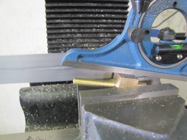
The angle I calculated at 10 degrees, so I used a protractor to set the cylinder block in the vise for drilling the passages:
While changing gears on the mill for selecting a lower speed for drilling and reaming the cylinder bore, the selection handle brokeoh: :wall: :
The selection handles on the mill are both pretty crappy and I have not been too happy with them. Now I have a GOOD reason to make some decent ones ;D ; I finished the rest of todays work by selecting speeds with a vise-grip pliers on the selector shaft.
The cylinder bore was done by drilling a 4mm hole through, followed by a 9.8mm drill, and then the 10mm reamer.
To drill the axial port holes, I just set the lot up by gripping the thin shaft in the collet chuck and mounting on center on the rotary table. I didn't bother to match any specific reading on the RT, and just used the DTI on the sides of the block to rotate it till it was square. Then offset in X on the mill by dialing the 4mm needed on the hand wheel, drilled the hole, rotated the RT 180 degrees and drilled the other hole. I used a piece of wire stuck in the port holes to feel when the drill broke through into the port passages "a la Troutsqueezer" - thanks for that tip Dennis! :
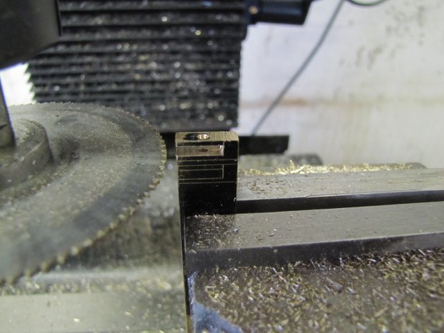
While I had things set up on the RT, cutting the slots in the bearing/valve was a no-brainer as well:
Then I turned some taper pins from some 2mm bronze brazing rod - using the flex away from the collet to my advantage. No need to set the top slide to turn the taper or anything; it comes out taper of its own accord:
The two taper pins - a bit crude, but will do their job well ;D :
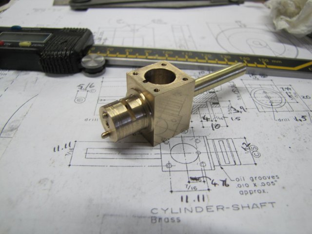
The taper pins were smeared with some high-strength retainer, and tapped in very firmly in the open holes on the valve. I'll trim the excess off at a later stage. Pretty much the finished cylinder block :
Oh yes, I forgot to mention that I opened the port holes about 1mm deep into the cylinder bore with a 1.5mm slot mill.
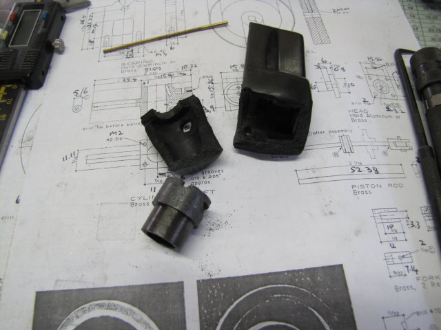
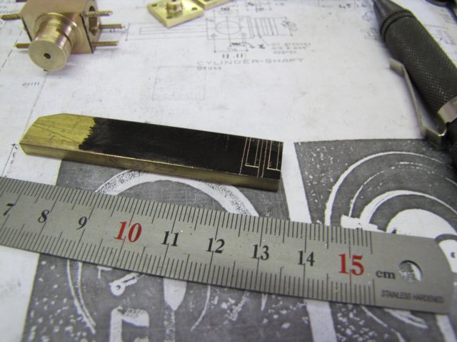
It was getting a bit late, but I felt like doing a bit more, so I made a start on the cylinder heads. I don't have solid brass stock close to the size needed, and while I could hack these out of some bigger stock, I'm a bit stingy. I could have used aluminium for the cylinder heads, but that just would not look right IMHO, so I settled on fabricating the heads from some 4mm brass plate I have, drilled to take some bits of 7mm round stock:
The round stock is over-long, to allow for some grip while machining.
I then silver soldered the lot together, and gripped each head on the shank in the 3-jaw and trimmed the bases down flush, and then turned on the 10mm register. Then I center-drilled and drilled through for the connecting rod. Elmer used a 2.3mm rod; I have a choice of 2 or 3.16mm, so I settled on using the 2mm, so the holes wire drilled 2mm, but with a very slow infeed and return to try and make them as smooth as possible. I don't have a 2mm reamer yet, and didn't feel inclined to turn a d-bit for this job.
To turn down and face the other side of the cylinder heads, I just clamped a piece of 2mm rod in the chuck, and with a piece of paper to provide friction against the chuck jaws and the revolving center in the tailstock pressed up hard against the workpiece, it was a doddle to do, as there was no real accuracy needed; just some clean-up:
At this point I stopped for today; there were ominous rumblings coming from both my tummy area and the dogs... Anyway I felt like a *beer* as well. So today's results:
Regards, Arnold
Today I pretty much finished the cylinder block.
First off, it had to be milled down to size. I used a DTI on the main shaft to check that things were square while setting up in the vise:
This process was repeated for milling all the sides to size, as well as for setting up to drill the mounting bolt holes for the cylinder heads.
To drill the ports, I used a method mid-way between Elmer's original one and the one suggested by Kevin & Gail. I decided on 1.4mm for drilling the passages, so I offset the start of the passages by 0.7mm from the edge of the bore instead of starting with the center on the bore diameter like Elmer's plans show. Then I calculated a reduced angle for drilling that would stay inside the block but would move the bottom ends of the holes further from the cylinder bore than using Gail's straight-down method. I wanted a little extra clearance, as cross-drilling brass have bitten me in the past; when the holes intersect things are inclined to grab and bite, and a straight-down hole would be close to the cylinder wall, leaving a greater chance of break-through.
Of course, one could drill the axial holes to depth first before drilling the cross-holes, but I went the other way around.
The angle I calculated at 10 degrees, so I used a protractor to set the cylinder block in the vise for drilling the passages:
While changing gears on the mill for selecting a lower speed for drilling and reaming the cylinder bore, the selection handle broke
oh: :wall: :
The selection handles on the mill are both pretty crappy and I have not been too happy with them. Now I have a GOOD reason to make some decent ones ;D ; I finished the rest of todays work by selecting speeds with a vise-grip pliers on the selector shaft.
The cylinder bore was done by drilling a 4mm hole through, followed by a 9.8mm drill, and then the 10mm reamer.
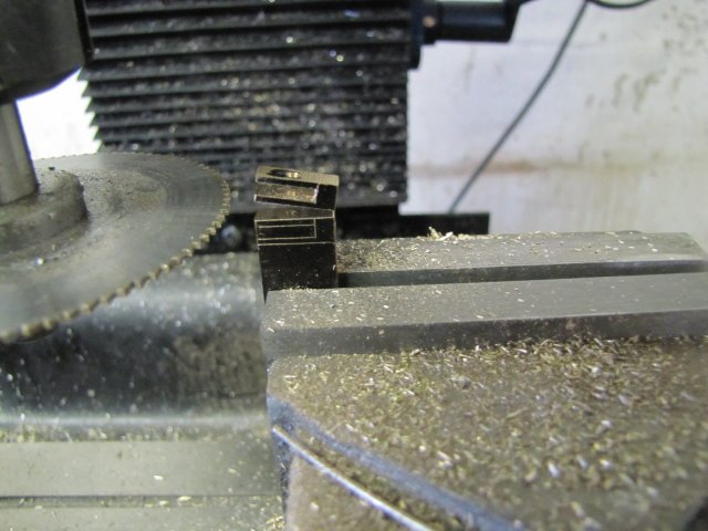
To drill the axial port holes, I just set the lot up by gripping the thin shaft in the collet chuck and mounting on center on the rotary table. I didn't bother to match any specific reading on the RT, and just used the DTI on the sides of the block to rotate it till it was square. Then offset in X on the mill by dialing the 4mm needed on the hand wheel, drilled the hole, rotated the RT 180 degrees and drilled the other hole. I used a piece of wire stuck in the port holes to feel when the drill broke through into the port passages "a la Troutsqueezer" - thanks for that tip Dennis! :
While I had things set up on the RT, cutting the slots in the bearing/valve was a no-brainer as well:
Then I turned some taper pins from some 2mm bronze brazing rod - using the flex away from the collet to my advantage. No need to set the top slide to turn the taper or anything; it comes out taper of its own accord:
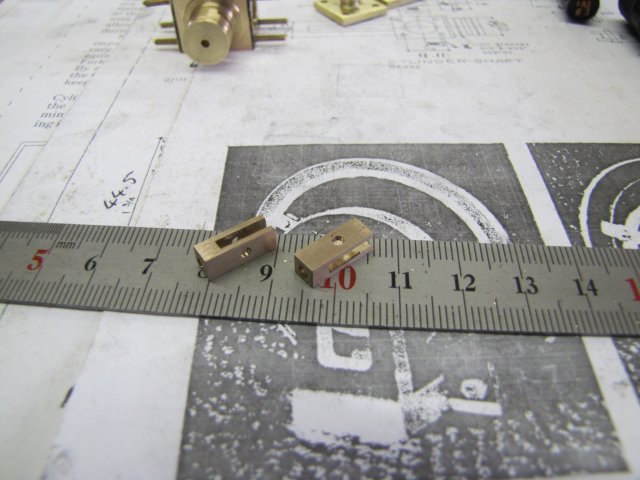
The two taper pins - a bit crude, but will do their job well ;D :
The taper pins were smeared with some high-strength retainer, and tapped in very firmly in the open holes on the valve. I'll trim the excess off at a later stage. Pretty much the finished cylinder block :
Oh yes, I forgot to mention that I opened the port holes about 1mm deep into the cylinder bore with a 1.5mm slot mill.
It was getting a bit late, but I felt like doing a bit more, so I made a start on the cylinder heads. I don't have solid brass stock close to the size needed, and while I could hack these out of some bigger stock, I'm a bit stingy. I could have used aluminium for the cylinder heads, but that just would not look right IMHO, so I settled on fabricating the heads from some 4mm brass plate I have, drilled to take some bits of 7mm round stock:
The round stock is over-long, to allow for some grip while machining.
I then silver soldered the lot together, and gripped each head on the shank in the 3-jaw and trimmed the bases down flush, and then turned on the 10mm register. Then I center-drilled and drilled through for the connecting rod. Elmer used a 2.3mm rod; I have a choice of 2 or 3.16mm, so I settled on using the 2mm, so the holes wire drilled 2mm, but with a very slow infeed and return to try and make them as smooth as possible. I don't have a 2mm reamer yet, and didn't feel inclined to turn a d-bit for this job.
To turn down and face the other side of the cylinder heads, I just clamped a piece of 2mm rod in the chuck, and with a piece of paper to provide friction against the chuck jaws and the revolving center in the tailstock pressed up hard against the workpiece, it was a doddle to do, as there was no real accuracy needed; just some clean-up:
At this point I stopped for today; there were ominous rumblings coming from both my tummy area and the dogs... Anyway I felt like a *beer* as well. So today's results:
Regards, Arnold
zeeprogrammer
Well-Known Member
- Joined
- Mar 14, 2009
- Messages
- 3,362
- Reaction score
- 13
Nice bit of work today Arnold.
Sorry about the selection handle...but it sounds like you were looking for an excuse to make some mods.
Sorry about the selection handle...but it sounds like you were looking for an excuse to make some mods.
It is always such a pleasure to see your work in progress Arnold, you make it appear effortless although and we all know the struggle it can be at times. Looking forward to seeing this one running, but am truly enjoying the ride. Thm:
BC1
Jim
BC1
Jim
arnoldb
Well-Known Member
- Joined
- Apr 8, 2009
- Messages
- 1,792
- Reaction score
- 12
Thanks Carl. Yes, those standard selector handles that came with the mill is pretty crappy; they fit very poorly and is (were) "spongy" to operate. New replacements was on my tuit list; I guess the priority just got boosted ;D
Sam, thank you! As to making it sound easy, maybe, but don't be fooled. Some of the things that may appear easy to me was very challenging when I did it the first time. Then, it became easier each time I did it. Then I become confident I CAN do it. And THEN I got reality checks on these "now-simple" operations and stuffed up famously ;D. After that, it's back to basics and a good bit of thought on how these now-so-simple operations are not "easy", but take a good bit of thought and attention - even if its quickly done.
Thanks Jim - the ride has gotten a bit bumpy though :-[ - Keep your seatbelt fastened!
Dean, thanks. :big: I think my fan also came off, so some remedial work will be needed...
Today I spent on making some of the smaller, but needed bits for the engine.
I started off with the forks (suitably adjusted in size for my thinner cam) marked out on a bit of brass stock:
In the photo, you can also see I added some 2mm threaded studs to the cylinder block - Yep, it will be studs 'n nuts once again.
First, I drilled all the holes needed and then I used a slitting saw to cut the forks; the piece of stock was just mounted vertically in the vise The first fork inside done:
Then I slit the top fork off the workpiece, to the point where it lifted up of its own accord and was held on by just a sliver of metal:
I just broke it off by hand, and proceeded the same way for the second fork.
After a bit of cleanup, I had two forks:
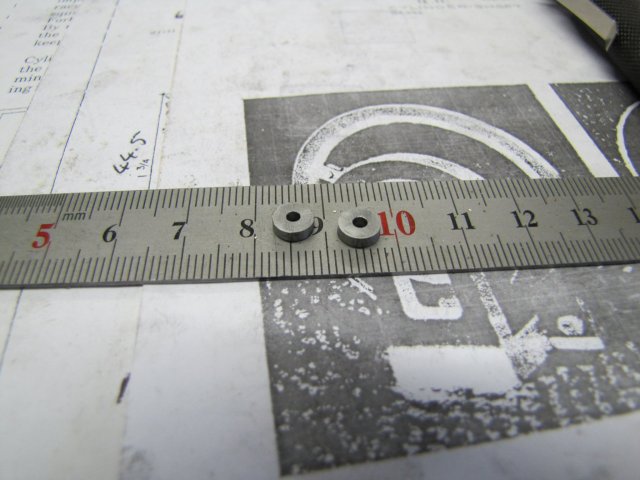
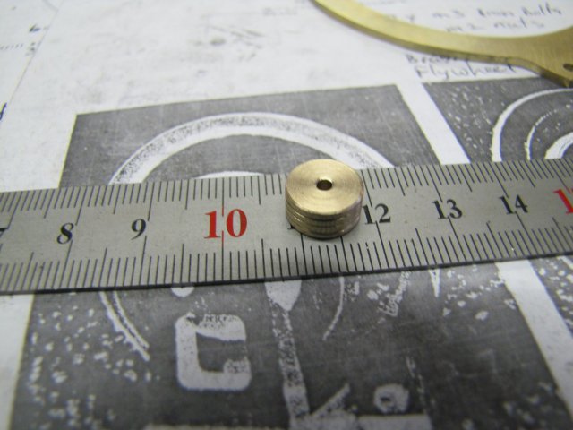
Two wheels soon followed - simple job; grab a bit of 6mm silver steel in the collet chuck, center drill and drill through at 2mm, then part off the discs - minimal clean-up with a file and some emery:
A couple of custom-made 3mm bolts from some 5mm hex stock:
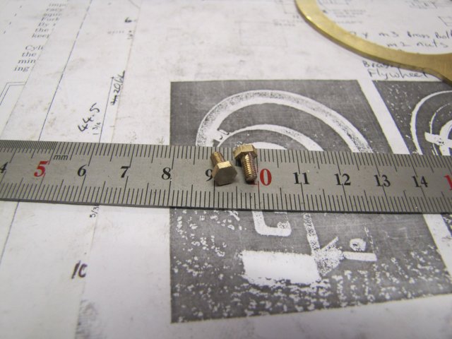
I LOVE those tailstock die holders!
The piston followed in rapid succession - turned it down to just over-size, and instead of using a threading tool to cut the oil grooves, I did them by eye with a triangular needle file, then a last facing cut to 0.01mm over size, parted it off half-way, and touched both edges with a needle file to clean those up. Then used some 800 grit "emery" and oil to get it to size (that last 0.01mm goes quickly!), then finished the part-off:
I then drilled and tapped the thick bearing block M3 to accept the steam/exhaust fittings - I forgot to do this when I made it initially :-[. Then I turned a fitting for connecting a steam (Air in my case :big pipe for now:
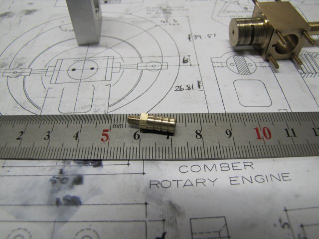
It's a bit "ugly", so I might re-do it later!
I stopped there for today; I wish weekends were longer! I need to make 8+ (+for the shop monster!) M2 brass nuts, shorten the studs, make a flywheel, some proper pins for the silver steel wheels, and do a bit of bling.
A quick assembly shot:
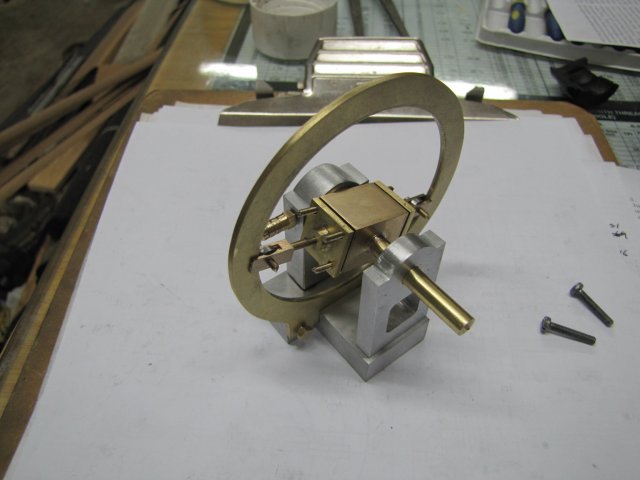
Elmer mentions in his build plans that a bit of fiddling and filing will be required... VERY true in my case; the assembly revealed that there are a couple of items that need addressing. I'm short of about 1.5mm of space on the thick bearing side; the cylinder and forks compared with the cam needs that much! I think I know how to fix that though . And my 10mm thick flywheel will have to be a bit thinner as well... 3/8" is only 9.53mm :big:
I hope the bling fairy is on standby for next weekend... I'll have a guest for most of this week (my sister's visiting ;D), so I can only get back to the build by next weekend.
Regards, Arnold
Sam, thank you! As to making it sound easy, maybe, but don't be fooled
. Some of the things that may appear easy to me was very challenging when I did it the first time. Then, it became easier each time I did it. Then I become confident I CAN do it. And THEN I got reality checks on these "now-simple" operations and stuffed up famously ;D. After that, it's back to basics and a good bit of thought on how these now-so-simple operations are not "easy", but take a good bit of thought and attention - even if its quickly done.Thanks Jim - the ride has gotten a bit bumpy though :-[ - Keep your seatbelt fastened!
Dean, thanks. :big: I think my fan also came off, so some remedial work will be needed...
Today I spent on making some of the smaller, but needed bits for the engine.
I started off with the forks (suitably adjusted in size for my thinner cam) marked out on a bit of brass stock:
In the photo, you can also see I added some 2mm threaded studs to the cylinder block - Yep, it will be studs 'n nuts once again.
First, I drilled all the holes needed and then I used a slitting saw to cut the forks; the piece of stock was just mounted vertically in the vise The first fork inside done:
Then I slit the top fork off the workpiece, to the point where it lifted up of its own accord and was held on by just a sliver of metal:
I just broke it off by hand, and proceeded the same way for the second fork.
After a bit of cleanup, I had two forks:
Two wheels soon followed - simple job; grab a bit of 6mm silver steel in the collet chuck, center drill and drill through at 2mm, then part off the discs - minimal clean-up with a file and some emery:
A couple of custom-made 3mm bolts from some 5mm hex stock:
I LOVE those tailstock die holders!
The piston followed in rapid succession - turned it down to just over-size, and instead of using a threading tool to cut the oil grooves, I did them by eye with a triangular needle file, then a last facing cut to 0.01mm over size, parted it off half-way, and touched both edges with a needle file to clean those up. Then used some 800 grit "emery" and oil to get it to size (that last 0.01mm goes quickly!), then finished the part-off:
I then drilled and tapped the thick bearing block M3 to accept the steam/exhaust fittings - I forgot to do this when I made it initially :-[. Then I turned a fitting for connecting a steam (Air in my case :big
pipe for now:
It's a bit "ugly", so I might re-do it later!
I stopped there for today; I wish weekends were longer! I need to make 8+ (+for the shop monster!) M2 brass nuts, shorten the studs, make a flywheel, some proper pins for the silver steel wheels, and do a bit of bling.
A quick assembly shot:
Elmer mentions in his build plans that a bit of fiddling and filing will be required... VERY true in my case; the assembly revealed that there are a couple of items that need addressing. I'm short of about 1.5mm
of space on the thick bearing side; the cylinder and forks compared with the cam needs that much! I think I know how to fix that though . And my 10mm thick flywheel will have to be a bit thinner as well... 3/8" is only 9.53mm :big:I hope the bling fairy is on standby for next weekend... I'll have a guest for most of this week (my sister's visiting ;D), so I can only get back to the build by next weekend.
Regards, Arnold