Building Elmer's #46 rotary

Home Model Engine Machinist Forum

Help Support Home Model Engine Machinist Forum:

This site may earn a commission from merchant affiliate links, including eBay, Amazon, and others.

arnoldb

Well-Known Member
Joined
Apr 8, 2009
Messages
1,792
Reaction score
12
When nearing the finish of my rotary table build, I started thinking on which engine project to take on next. I just couldn't make a choice between the three candidates I had lined up... Last week my sister slept over for a couple of nights, and I showed her the three, and she "chose" Elmer's Comber.

I haven't been able to find much information about building this little engine - there's a couple of videos on the Internet, and what appears to be an unfinished team build (TB2) here on HMEM, so I'll bore everyone by doing a bit of a build log.

This engine's construction seems relatively simple, but running through the processes in my head to make the parts, its evident that high accuracy will have to be maintained to get a good runner. The most demanding part to make will be the cam. I've also had to re-work some dimensions to fit available material and tools I have - mostly to convert things to metric. One material change I had to make is to use 2mm brass plate for the cam instead of the 1/8" (~3.2mm) called for - I think this will be OK.

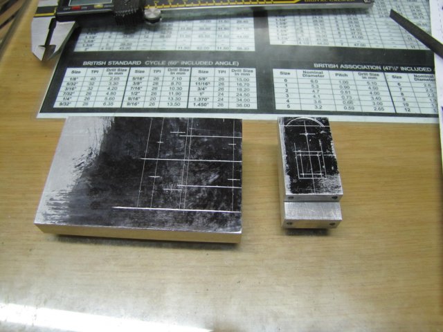
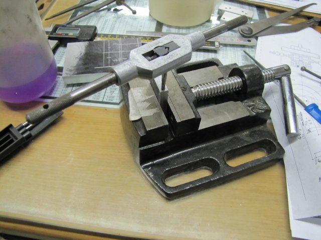
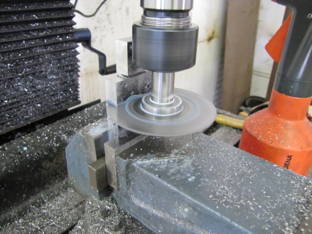
I started out on the base today. I don't have a set of parallels yet, and my vise is too deep for milling the slot in the base with the 2mm cutter. This slot has to be as accurate as possible to keep the cam square, so I used my DTI to check all the levels (both X and Y) while clamping the base block down in the top of the vise. As I was tightening up the vise, I had to re-check the levels all the time, and with taps with a hammer to keep things level (of course, after removing the DTI from the workpiece each time when I did this!):
normal_IMG_1422.JPG

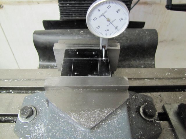
The DTI is clamped in a collet in the mill's collet chuck.

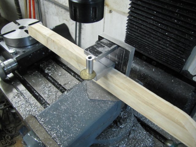
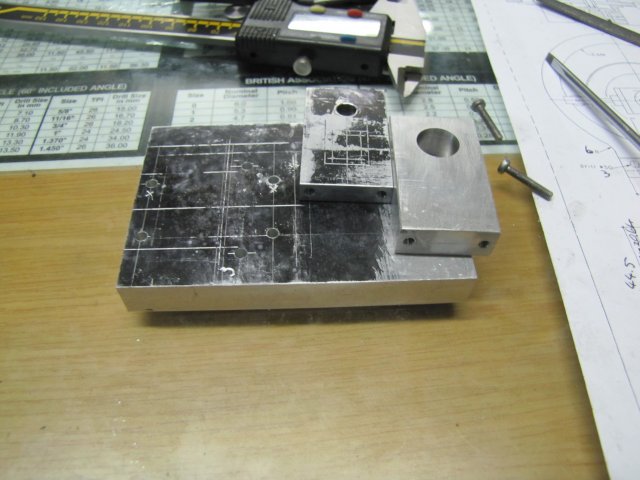
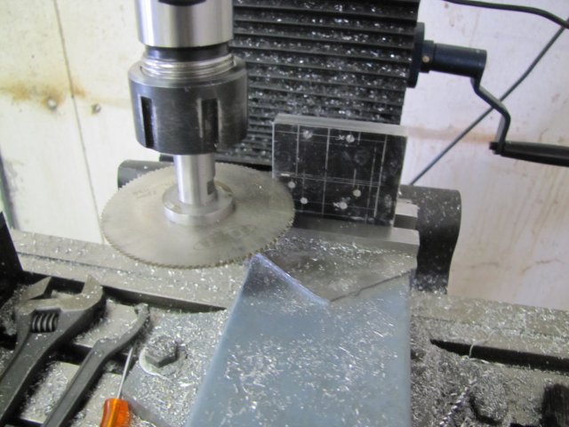
A drawn-out session of milling followed - 1mm depth of cut to get the 6.35mm depth into the slot; this is actually over the depth my 2mm slot mill can cut, and the last .35mm caused it to slightly open up a small "V" at the top. A 2mm thick slitting saw would have been much easier and quicker. While the block was in place, I drilled the mounting holes for the bearing blocks as well, using the mill's hand wheel calibrations. Instead of #5-40, I'll use 3mm screws.
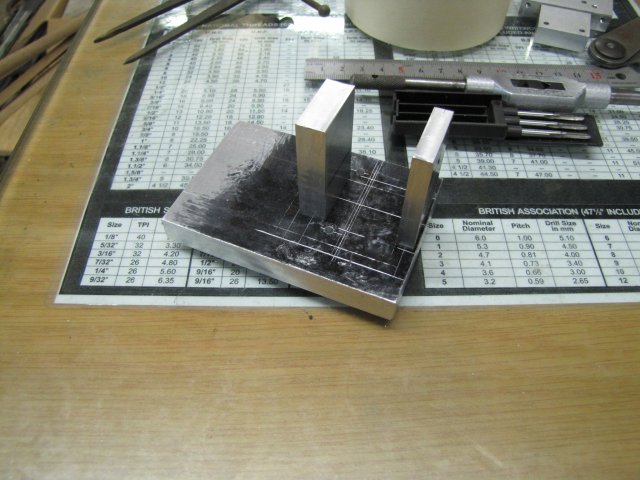
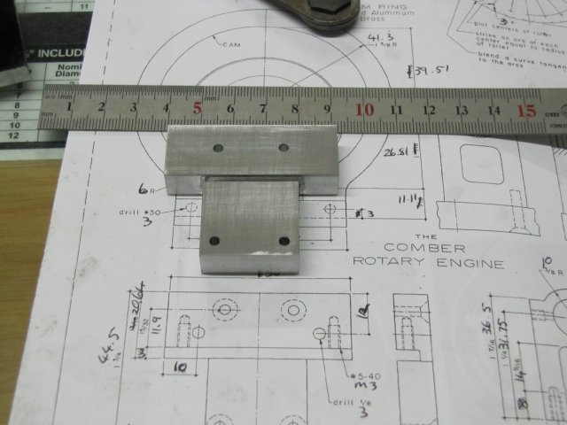
Then I roughly bandsawed the excess "blocks" off, and finished off the cut-outs with a 14mm end mill to size.

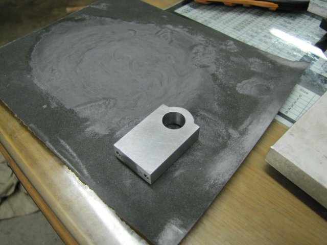
Not much to show for today's work - the base as I finished shop for today; it still need mounting holes drilled to mount it to a display base, as well as drilling and tapping mounting holes for the cam:
normal_IMG_1424.JPG


Regards, Arnold
 
Arnold, that's a very interesting engine and it will be fun to watch your progress. It has an exotic feel to it and will look very nice sitting up there on your shelf.

-Trout
 
I've never seen one but for the pics in the prints, Arnold. I think you're safe in having one that
won't show up everywhere. At least, not yet! Once you get going, others will probably want
to try it too.
This looks like another fun "Arnold build"!

Yay!

Dean
 
This is quite an intriguing engine, Arnold.

I will definitely be watching this one.

Kel
 
Trout, Dean & Kel, - Thanks guys.

I'm having a bit of a slow start on this one though; first of all is a line-dance "take one step forward and two steps back"...
The base as made is scrap, as I mis-calculated the position of one set of bearing holes... I found that out yesterday evening after trying to do some work; in fact, I finished all the other holes and tapping and the base and started on the cam. At one point, I put the cam plate in the base and something just did not "look" right; that's when I discovered the booboo :-[. Oh well, I'll just re-make the base, and having some further thoughts, it might be better to finish the bearing blocks as well, and line-bore them mounted on the base before making the cut-outs and milling the slot in the base.

We are having a very sudden and very cold spell (you guys in the colder climes stop laughing; -4C is darn cold for us!), and trying to mark out accurately is no fun when one's shaking all over the show (no heating in my shop) - so evening work is out for now :(
I might be out of town this weekend as well; our winter hunting season has opened here, and I got a call today that I might be in line for half an oryx if I'm prepared to visit a friend this weekend. My freezer's a bit bare, and that is meat for at least six months, so if it comes off, I'll be butchering meat instead of metal this weekend :big:

So don't hold your thumbs; I'll most likely have to dig this thread out of page 4 by the time I get back to it ;D

Regards, Arnold
 
Hi Arnold, Oryx huh? I hear that it tastes a lot like chicken :big: Seriously, that sounds like a great deal to me. one does not live upon metal shavings and water alone. Having never had the opportunity to try a bite, I suppose the closest thing to that we have here in the states to compare it to would be venison of some sort, which I have had and enjoy tremendously. Does it cook up 'greasy' or pretty lean?

Too bad about your base plate, however, from having seen your work, I'm certain the end result will be such that no one will be the wiser. Thm:

BC1
Jim
 
Arnold,
This is a fun engine.
If you are looking for additional information on this engine, search for "Coomber engine" on the internet. Notice the extra "o" in the name. When Elmer published his design he spelled the name of the original engine incorrectly and it carried through in to the Elmer's engines book.
Gail in NM
 
Arnold,

For sure one does not live by Oryx, metal shavings or..................................


[ame=http://www.youtube.com/watch?v=SU-CPkKw5lY]http://www.youtube.com/watch?v=SU-CPkKw5lY[/ame]

Best Regards
Bob
 
:big: :big: I dunno Bob, I think there is something wrong with that boy.

BC1
Jim
 
Arnold,

The #46 engine sure looks interesting.

I'll be watching your build closely.

Get your freezer filled so you will have plenty of well nourished shop time.

Happy hunting.

SAM
 
I've said it before...I love building Elmer's engines. This one is definately on my list but after Elmer's geared engine I needed a break. I'll have just as much fun watching you "have fun" building it.

Looks great so far!

Chris
 
Too bad about the mix up, Arnold. All of us who make chips know, "That's the way it goes!".

Hope you have a good hunting trip. It's all elk, deer and moose here. Tasty critters.
Show us what you get!

Dean
 
Thank you John. Yes, I saw the TB2 log and went through it and the related posts. I might have missed some; some more re-reading is required :) Pity though that the TB appears not to have finished... I hope I'm wrong about that because there appears to have been a lot of effort put in.

Thanks Gail; yes it appears to be a fun engine as you should well be able to attest ;D While researching I found the "Elmer" oddity of having the Coomber incorrectly spelled. Turns out Mr Coomber (if it's the same one) was not only associated with the round cam; there are some nice Coomber based table engines out there as well.

Jim, Bob, Sam, Chris & Dean, thanks guys :)
The little set-back on the base is no big deal - I get to make it better the next time round - and with different methods as well :big:

:big: Bob - I think I have to agree with Jim though; there seems to be something wrong with that lad; it appears he can't multi-task :big:

Now COMPLETELY
Smileyofftopic.gif

As to hunting, well, I won't be doing that this time round; my friend's neighboring farm is a game ranch, and they have a group of trophy hunters in from the USA currently. The hunters want the oryx heads to stuff and hang on walls, and the bloke who owns the farm sells off the rest of the carcases for home consumption. While I love shooting (I'd happily shoot at targets on a range all day), I'm not a keen hunter. Only if I need food I'll hunt, but I really dislike pulling the trigger on a live animal - it's one of those things that have to be done though.
Oryx meat taste less "gamey" than other species of buck here; in actual fact most people cannot distinguish it from beef, but it is very lean and treated properly very nice and tender.
As to the critter in question; these are magnificent animals with a really mean demeanor when hurt, and tough to get down; they have killed many people in the past. I have shot only a smallish one about two years ago - I don't want to make the photo show up here as its a bit gory and might be offensive to some. We took the photo as an after-thought and only had a cellphone camera available. If you want to have a look, you can see here. I must say though; it supplied me with a lot of food. The only mementos I have of it now is two photos, the .303 spent cartridge casing, and a "knobel" (German dice-game) cup made from dried skin - don't ask about the "parts" that came from!

Regards, Arnold
 
;D With a freezer bountifully replenished, and warmer weather since the weekend, I had a chance to get into the shop yesterday evening and today.

Yesterday, I marked out a new base (intentionally leaving a lot of excess stock on it) as well as the bearing blocks, and milled the bearing blocks down to size. I also drilled the bearing block mounting holes for threading, but stopped there:
normal_IMG_1428.JPG

Funny how just truing up and marking out blocks of aluminium can take two hours to do...

This afternoon after work, I tapped the bearing blocks mountings to M3. A little drill vise is handy to hold onto smaller parts while tapping free-hand like this; I still need to build or improvise a tapping stand:
normal_IMG_1429.JPG


Then I drilled the mounting holes in the base plate using the same setup as for the stuffed-up base plate and counter bored those for some 3mm screws I had, and mounted the bearing blocks in position:
normal_IMG_1430.JPG


As mentioned in a previous post, I felt it would be better to machine the bearings in-position on the base. I could do it on the lathe with the vertical slide mounted, or I could try doing it on the mill... I opted for the mill, and ended up with a way-out weird setup. The one bearing needed to be drilled to 5.9mm and reamed to 6mm, and the other needed to be reamed to 12mm (closest I have to 1/2"). I don't have machine reamers, but my hand-reamers would work, though these need a lot more travel to ream to size. Also, the bearing block with the 6mm hole is quite thin, and would easily bend away. I ended up mounting the lot as shown in the mill (Professional machinists divert your eyes and laugh quietly):
normal_IMG_1431.JPG

The base was set square vertically to the mill vise with the wood block supporting the bottom bearing block. Odds 'n ends (a bit of scrap ali and a coin) making a light fit between the lower and upper thinner bearing block would support the upper block while drilling.

Next, I drilled a 5mm hole through both blocks with light pressure, and then drilled (5.9mm) and reamed the top block to it's 6mm size. Then I simply unscrewed the top bearing block, and without having to adjust the mill head's height, with VERY light pressure drilled the bottom bearing out to 11.5mm. I didn't comment on the thread from Student123 about trying to ream to 0.5mm over drill size, but I had to do it here, as I keep forgetting to buy an 11.8mm drill for my 12mm reamer. Well, it worked. I just had to take things very carefully and slowly; ream a bit - about 1mm down-feed - and lots of lube (I use methylated spirits for aluminium), raise and clean the reamer flutes with a brush (they clog up quite quickly!) after about every 1mm of infeed, and repeat. It took me a while; the mill was running at it's lowest speed to "simulate" conditions for a hand-reamer like I was using here. Things turned out well though ;D

End of work today; a half-made base, and two bearing blocks that need cosmetic finishing. I scribed two little X's on the base and the bottoms of the bearing blocks where these won't be seen; this is to help alignment when doing final assembly:
normal_IMG_1433.JPG


Regards, Arnold
 
Congratulations on getting the freezer restocked! At least you know you won't starve any time soon.

Some advice for when you get around to making the cylinder block...
Drilling the angled ports can be somewhat challenging as there isn't much room for error, as I found out. I drilled a little too close to the cylinder and it caused the wall to break out somewhat. You can see in the picture that the ports are longer than they should be.

http://www.homemodelenginemachinist.com/index.php?topic=2390.msg31813#msg31813

I'd suggest following Gail's advice and drill straight down and add a relief at the top.

http://www.homemodelenginemachinist.com/index.php?topic=2390.msg32954#msg32954

I did it both ways and the straight down method worked much better.
 
Hi Arnold;
Your parts came out well, and the part about "pro machinists divert your eyes" is nothing to worry
about! If you've seen the setups I have in job shops you'd know you're doing just fine. Needs must,
and the customer doesn't know how the job was done. He just knows the job fits!

Your game shot looks like most. We all eat! Actually, what you have there is a lot less messy than
how things look when animals eat other animals. What a mess that is when I come across a carcass
that was taken down by wolves or a cougar! Especially wolves.

Dean
 
Thanks for checking in and the heads-up on machining the cylinder Kevin - that is MUCH appreciated! I see you also silver soldered the shafts in; Ill go that route as well.

Thanks Dean. Somehow I'm not really too bothered by the pros though ;). As long as a setup is safe and it works to make the parts, anything goes in my shop ;D
Yes, we all eat; problem is there are many people who think meat comes from packets in a supermarket... Have you ever seen a video clip of African Wild Dogs hunting ? - that can be really gory, but its nature's way.

No photo today; I'll add it to my next post. This afternoon I just rounded over the tops of the bearing blocks like I did for the grasshopper engine. I was pondering some ways of using the rotary table to do it, but all the ways I could think of would have taken longer to make jigs and set up than just milling some facets and finishing with a file.

Regards, Arnold
 
Well, a little bit of progress ;D

The one bearing block after some clean-up on some 320 grit emery and oil on Thursday evening:
normal_IMG_1435.JPG


This morning I continued with work on the base. Instead of milling the slot for mounting the cam, I cut it with a slitting saw. The excess stock I left on the base helped a lot, as it was easy to get enough clearance all-round using this simple setup:
normal_IMG_1438.JPG

I may have cheated a bit... I used my 1mm thick slitting saw and made two passes to get the 2mm wide slot I needed. This may not be a correct operation for a slitting saw. On the second pass, I used a much slower rate of feed, to try and keep the saw from flexing up into the previous slit while cutting.

While I had the slitting saw set up, I just used it to cut out the sections from the base that needed cutting out; made for a much nicer operation than hacksawing and milling these to size. Much easier to clean up as well, as the slitting saw leaves a really good finish on the cuts. As a near-final operation, I slit the base away from the excess stock - an action photo for a change:
normal_IMG_1439.JPG

I didn't slit all the way through; I stopped with a small bit still holding the base on to the stock and simply broke it off by hand rather than running completely through and have the base fly off into the workshop (or me!). The nub that was left when broken off I just filed off before cleaning up the base on emery paper.

Next up, the cam... I'm no math wizz, but I do like to know how and why things work. Before I even began this build I studied Elmer's plan and tried to figure out a formula for calculating the cam profile. Elmer's cam design is based on angles of rotation and offsets based on the piston stroke related to those angles. Not a simple concept to explain in words, but the cam profile would come out to a "circle" that is slightly "less curvy" at the top and bottom; i.e. an ellipse. I worked out a formula based on the cosine of rotation... After I did my brain-busting, a pointer revealed that Gail (GailInNM) has already done the thinking - (Thanks Gail!) based on the sine of rotation. With reference to Gail's spreadsheet, my own calculations were right, except that they were 90 degrees rotated. Gail's cam profile file can be found here on HMEM :)

I have a "new" RT that I'm itching to use "in anger". I've already cut a bit of brass plate to make the cam from. There are some mounting difficulties to mount the plate to my RT, but I think I have those figured out... One thing that would be difficult, is to dial in the offsets needed to machine the cam on the mill's wheels. So I spent some time to add a crude DRO to my mill :big: - A while ago I splurged on some more CCC (Cheap & Cheerful Chinese) digital calipers, and I temporarily mounted the 200mm one I bought to the mill X-axis. A bit crude, but it should work ;D:
normal_IMG_1441.JPG


After a bit of clean-up and assembly, today's results; the base and bearing blocks done... Not quite... I just noticed I still need to make the inlet & exhaust port holes on the thick bearing block! :-[ :-[ :-[ :
normal_IMG_1443.JPG


Regards, Arnold
 
Hm...your DRO is making me think about going the same way. It's not like I need a readout at some angle from the action. I'm typically just turning one axis at a time anyway. I'll think on this some more.

Yeah...you're liking that mill aren't you?
 
Back
Top