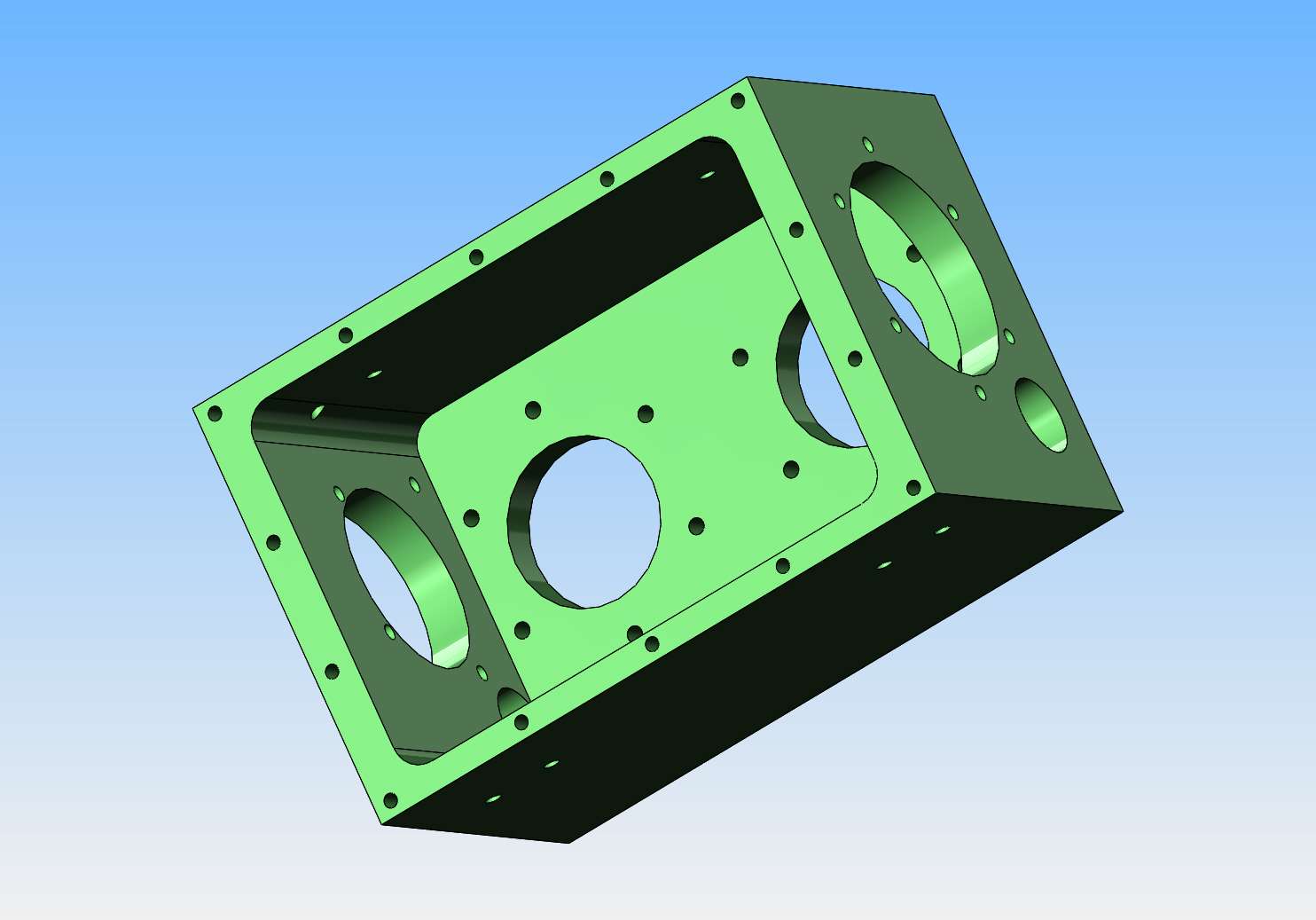
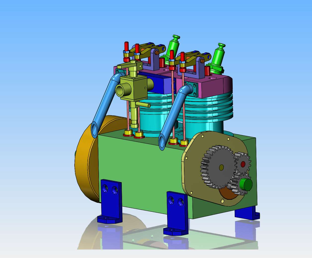
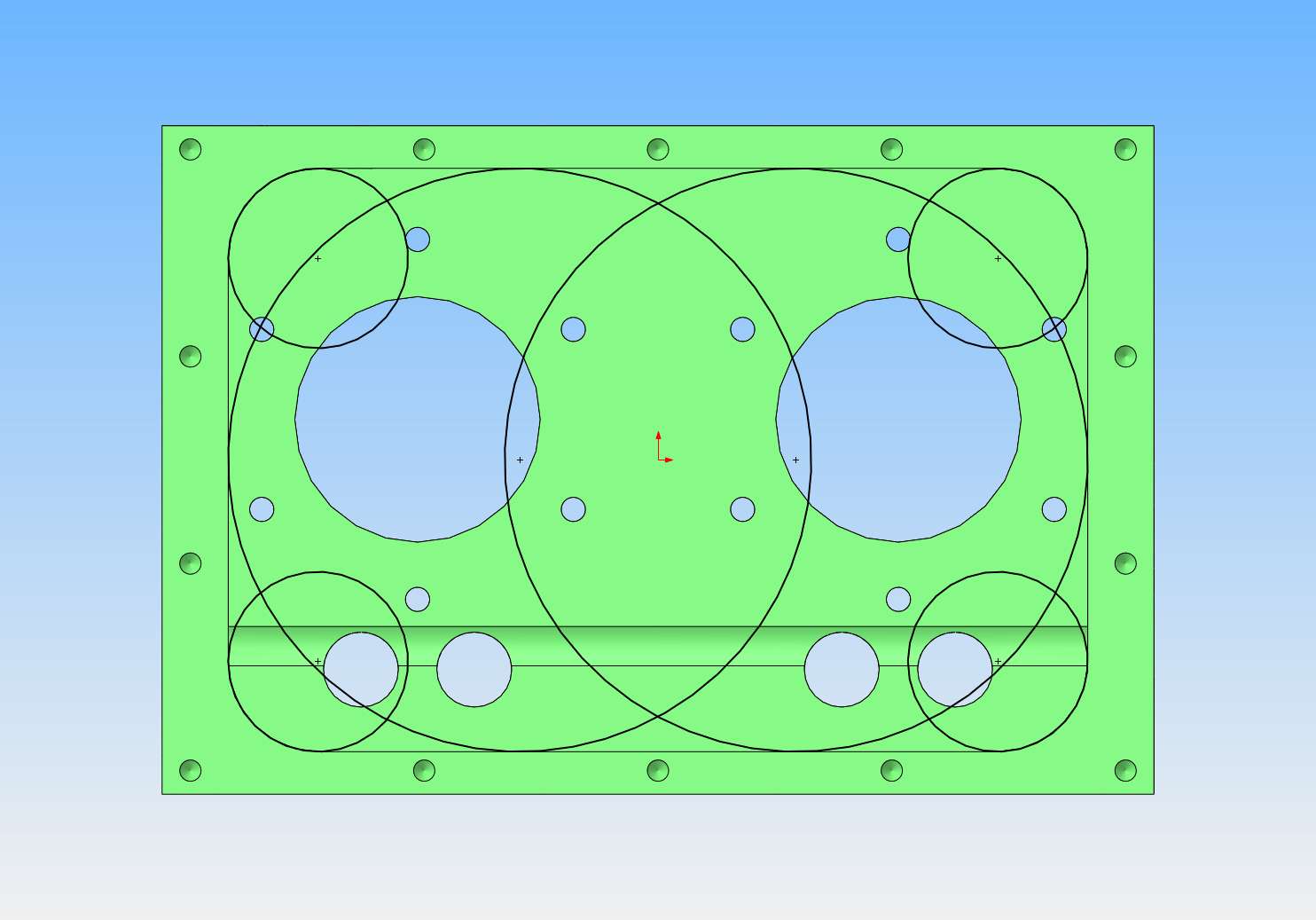
The redesign of this engine is mostly finished. It has a 1" bore and ended up with a 0.944" stroke. The three worst parts to machine will be the crankcase, the crankshaft, and the cams. I think I will machine the crankcase first. The crankcase looks huge, but in reality it's a bit less than 3" square and 4 1/8" long. The hard part is going to be the large cavity in the crankcase which is 2 1/8" deep, and is "blind" meaning it doesn't go all the way through. The radius in the corners is 3/16", so first step will be to drill the four corners with a 3/8" drill to full depth and then finish up with an endmill to get a flat bottom. Then mount it on the lathe faceplate and do a couple of overlapping 2.43" diameter blind bores to hog out the rest of the material. This will still leave some material to be removed from the corners that can probably be cleaned out on the milling machine. I think this is the best approach with a home shop/ manual mill and lathe. if anyone thinks of something better, please let me know.