Building a model Gas Tank

Home Model Engine Machinist Forum

Help Support Home Model Engine Machinist Forum:

This site may earn a commission from merchant affiliate links, including eBay, Amazon, and others.

Brian Rupnow

Design Engineer
Project of the Month Winner
Joined
May 23, 2008
Messages
14,976
Reaction score
8,268
Location
Barrie, Ontario, Canada
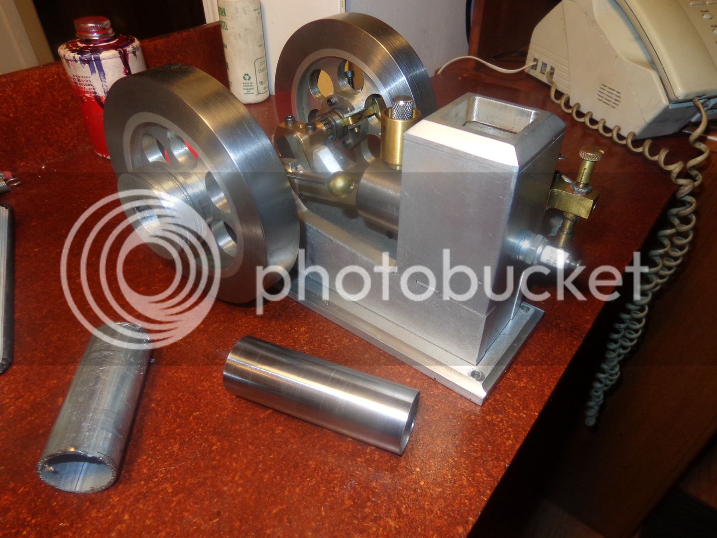
When I built my Philip Duclos "Odds and Ends" engine a couple of years ago, I never did build a satisfactory gas tank. I have some "down time" now, so thought perhaps I should build a gas tank for it. Since I don't have a separate base that the engine mounts on, I have decided that the gas tank must mount on the engine itself. A hunt through my "bits and pieces" bin yielded a length of galvanized steel tubing 1.165" outer diameter x 1/16" wall thickness. I didn't want to have to deal with the galvanized finish, so I set it up in my lathe and turned the outer diameter to 1.144" diameter, which (I hope) got rid of the galvanizing on the o.d. of the pipe. The piece I turned is 3.48" long. This was a somewhat arbitrary length, but all that matters at the moment is that it be 'long enough". In the picture you can see the unturned length and the turned length setting in front of the engine.
 
I had already modelled the engine before I built it, so today it was simply a matter of bringing up that cad file, and adding in the tank body (in red) and designing a bracket to hold the tank (in dark blue). I have some thoughts as to what the rest of the tank is going to look like, so tomorrow will model them and then setting about building them.
 
I don't expect that anyone is going to build this, however---I have to build it myself, and I need a drawing to do it. It requires no effort for me to post it, and it gives the new guys something to think about. The steel gas tank body will be inserted into the round hole in the bracket and secured there with #638 Loctite. The only thing of importance with this bracket is that the top of the gas tank MUST be 1/2" to 3/4" below the center of the carburetor barrel. The small carburetors on these hit and miss engines have no float and shut off valve, so if the level of fuel is ever higher than the fuel port in the air intake/needle valve assembly in the carburetor they will flood like crazy and fuel will gravity feed from the tank and drip out the air intake side of the carburetor. This makes the engines almost impossible to start and can also be a major fire hazard.
 
This gets rather interesting as the design develops. One picture shows what the finished engine looks like mounted on the engine. The other picture shows a section view through the center of the tank. This is going to be a "no soldering involved" tank, completely assembled with 638 Loctite. The main tube is mild steel, the ends are machined from aluminum, and the filler neck and cap will be machined from purchased brass plumbing fittings. The small tube that runs out to fed the flexible gas line will be machined from mild steel. I'm not 100% sure yet, as to whether I will use 638 Loctite as the bonding agent or J B Weld. They both stand up well to fuel immersion, and they both are super strong when fully cured.

 
While driving around town to buy some material, I got thinking about this tank. It needs one more hole thru the aluminum at the end where the filler cap is, to prevent it "air locking" as it is filled with fuel. Without the hole which I have added, I would have only been able to fill the tank to the top of the center hole thru the aluminum, and then it would have air locked and not taken any more fuel. With the added hole, any trapped air can escape and let me fill the tank almost to the top. I also added a breather hole thru the center of the screw on cap. The threads on the inside of the cap are tapered pipe threads, as are the threads on the fuel filler pipe, and I have found that even though I unscrew the cap a full turn to let air into the tank while the engine is running, the weight of the cap makes it vibrate closed and shuts off the air flow, causing the engine to starve for fuel, again because of an "air lock" situation.
 
In the picture you can see the "gas cap" as purchased. It has a rough cast exterior. Beside it you see the same part, after a little cosmetic work in my lathe. (That's the gas cap off my dual opposed piston engine). The pipe nipple which the cap screws onto will have one end cut off and be turned down to match the hole in the aluminum tank end. Also shown in the picture is the "blank" end cap for the far end of the gas tank. There is a small trick to it. It has to intrude into the end of the tank about 1/2" to ensure enough material that the Loctite can get a good leak-proof bond between it and the outer tank shell, but if I didn't but the big counterbore in the end of it, I wouldn't be able to get as much fuel into the tank as I want. This way, the counterbore fills up with fuel too, so I don't lose much tank capacity.
 
Hey!! I'm starting to like this!!! There is a lot of work in that large aluminum end, but all the parts go together and I think it looks good. I have temporarily ran out of 638 Loctite, so I am going to do all of my assembly with J.B. Weld. I have two tubes of it that may never get used up, so they might as well be used for this.

 
It doesn't get a whole lot better than this---as far as fit goes, anyways. There is a small bit of deception in the picture, because I haven't completed all of the joints which are being "glued" together with J.B. Weld. I haven't used J.B. Weld in an application like this before, so want it to have a full 24 hours drying time before I put any pressure on it or try to put fuel in the tank. I will finish those joints this afternoon and then wait a couple of days before I test it with fuel in it.


Brian,

It is interesting, just not something I have an immediate interest in.
Maybe in the future, but not now.

Come to think of it, I don't think I've ever seen one of your projects that wasn't extremely interesting.

Steve Fox
 
Thanks Steve.--It's unusual to start a thread and go all the way through it and not have someone comment. I'm finding all of the forums I post on to be unusually quiet right now. It could be that with spring weather finally putting in an appearance people are doing spring things instead of playing on the internet.---Or---It could be that I've just posted too much over the last 5 months.---Brian
 
dont stop posting i need something interesting to read and store away when i cant sleep at night
fuel systems is something i lack on on my engines last week i had a display and had three engines running on one communal tank o k but one chap wanted to put my little hit and miss beside his huge full size bessemer and run them both side by side but couldnt due to lack of its own fuel tank so thanks from here for the tank idea
 
Last edited:
I was thinking every one was at cabin fever:hDe: with the forums being so quiet.
Lookin good Brian


Tom
 
Archer--It seems like most of the people I know have moved from this forum over to the other one.--and they aren't posting much over there right now either. It could be that everybody has gone to one of the big model shows, or it could just be that its spring and people are tired of being cooped up all winter in their machine shops. The Home Shop Machinist website got hacked, and they are having problems restoring it to full function.---Brian
 
Brian,
I follow along on all your posts on both this forum and MEM. The comments are different and so information from both is valuable. A lot of regular posters in the eastern area of USA and Canada have been getting ready for the Cabin Fever event and are now returning home so postings will pick up I am sure. I have been using the forum slow time to get some things done in the shop as well as on my build. While comments are great they do take away from building time. A lot of people follow along as you know. You have well over 800 views on this thread so that's not all bad.

Any how, as always, this is a great build thread.
Gail in NM
 
Here is a short video with the new gas tank on the running engine. There is a link to Photobucket, also to Youtube.
[ame]https://www.youtube.com/watch?v=mxc_NZ_29yc&feature=youtu.be[/ame]
 
Now I have to play detective. I'm really not sure if that annoying "clank clank" noise is from the long rocker arm or not. EDIT--I think perhaps its just the nature of the beast. That desk the engine is running on is hollow, and it amplifies all the sounds like a drum. Since I have everything out to run my engines, I have put away the Odds and Ends and am now running my Kerzel on the same desk, and its twice as noisy as it is when its running on my heavy work bench out in the main garage.--I'm not going to worry about it!!
 
Last edited:
I took another look at the engine trying to run down that clank clank noise--its making me crazy. I have just found out that when the roller bearing on the end of the long rocker arm is fully "up" on the tip of the cam, there is no slack in the system anywhere. It seems that the exhaust valve is open as far as it can go, and is actually "bottoming out" against the head of the intake valve.--Definitely not a happy thought. The only thing preventing major damage from being done is that the long thin rocker arm has some flex in it. I am going to adjust the shcs which bears against the head of the valve until I have a bit of clearance in the "exhaust valve open" position and see if that gets rid of my clank. I held the intake valve open with my finger and rotated the engine by hand, and I can actually feel the exhaust valve hit the head of the intake valve and force it up.
 
Last edited:

Latest posts

Back
Top