Brian's Donkey Engine

Home Model Engine Machinist Forum

Help Support Home Model Engine Machinist Forum:

This site may earn a commission from merchant affiliate links, including eBay, Amazon, and others.
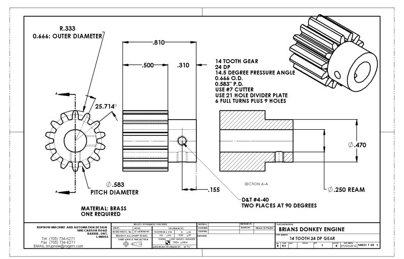
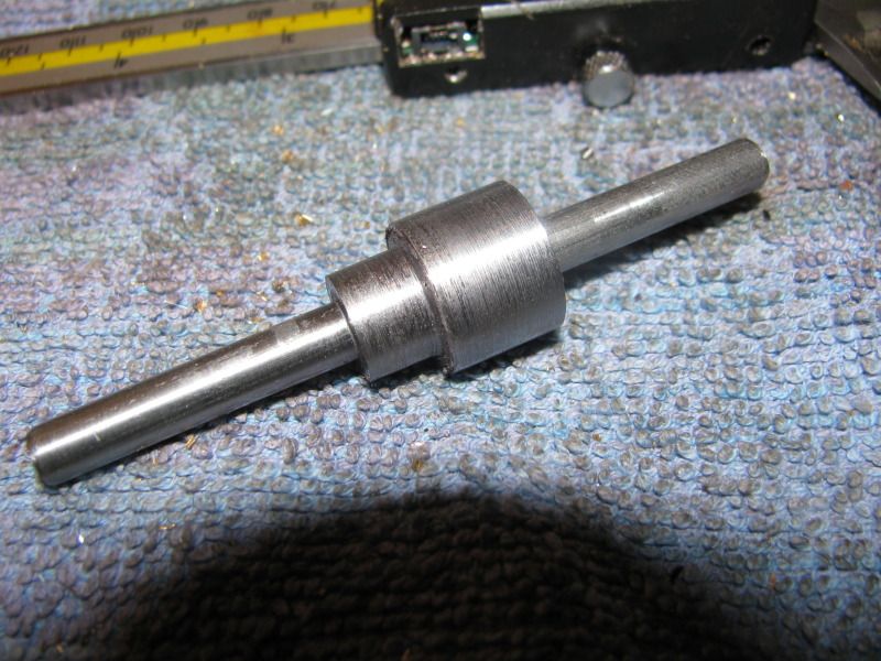
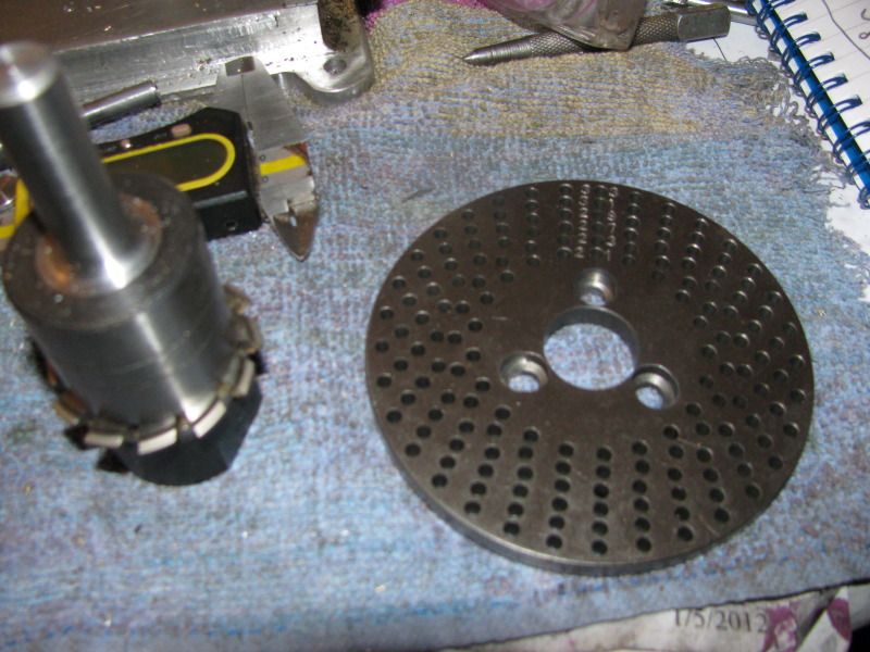
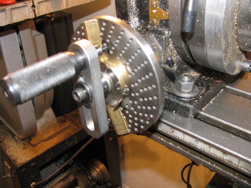
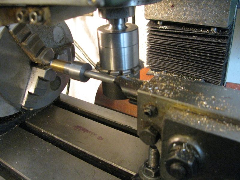
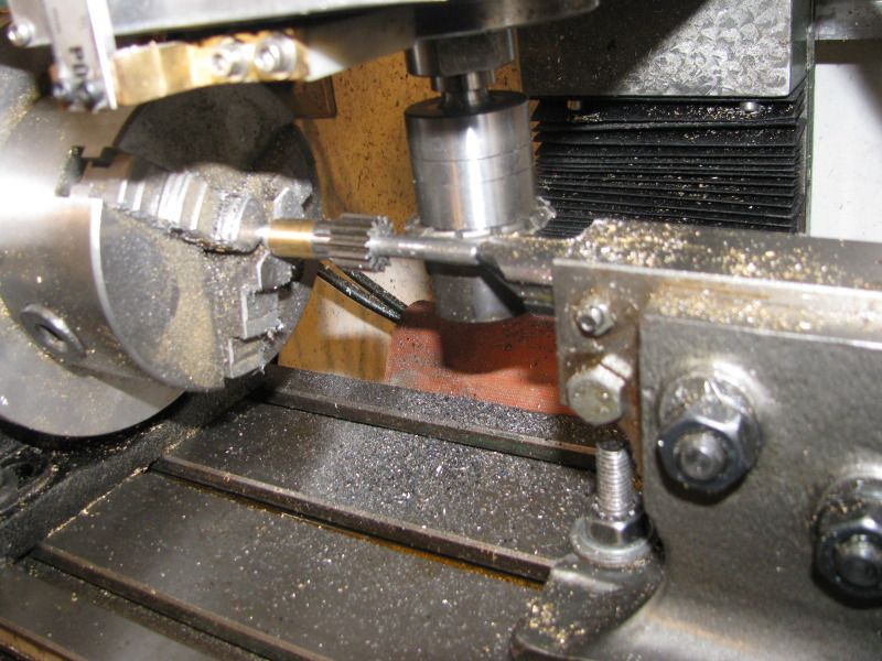
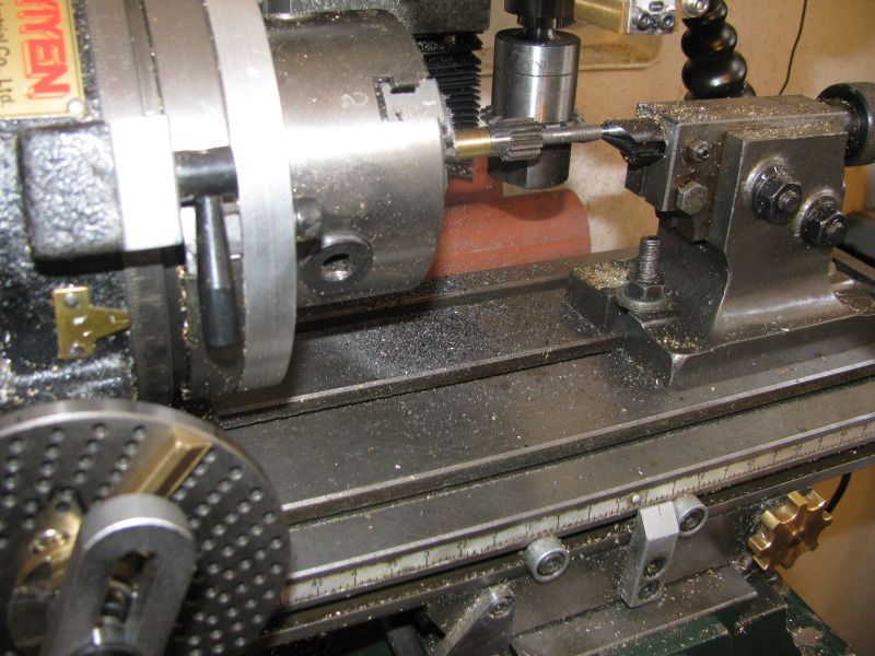
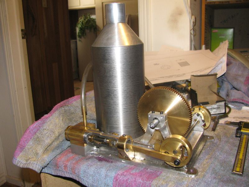
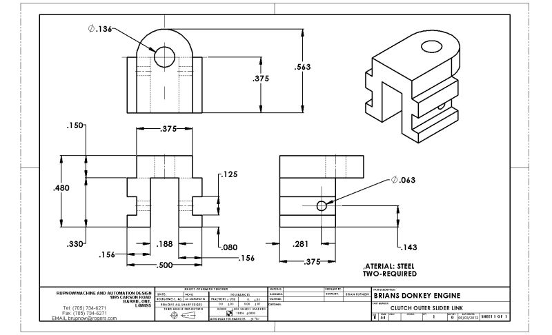
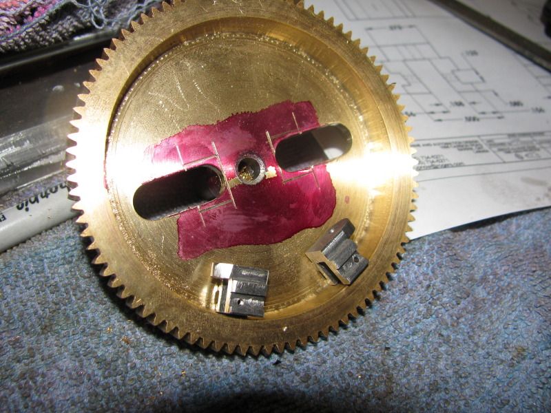
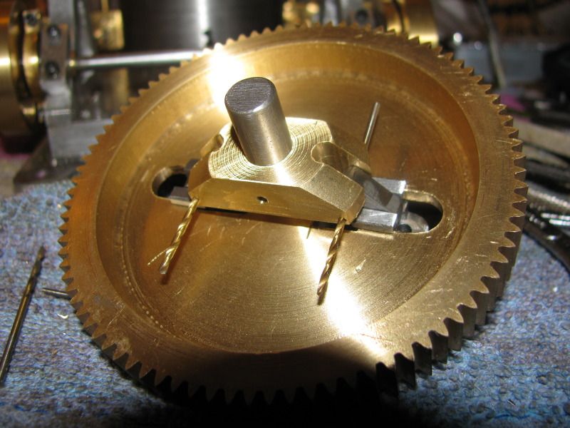
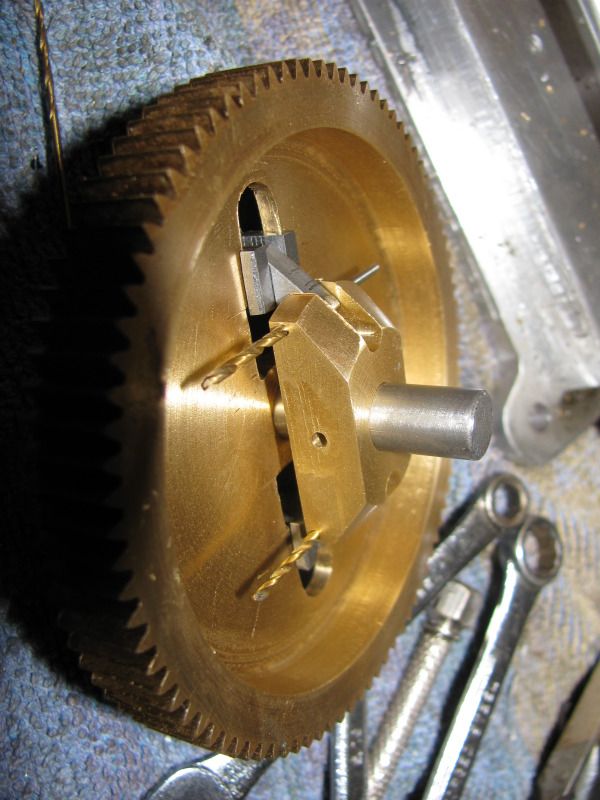
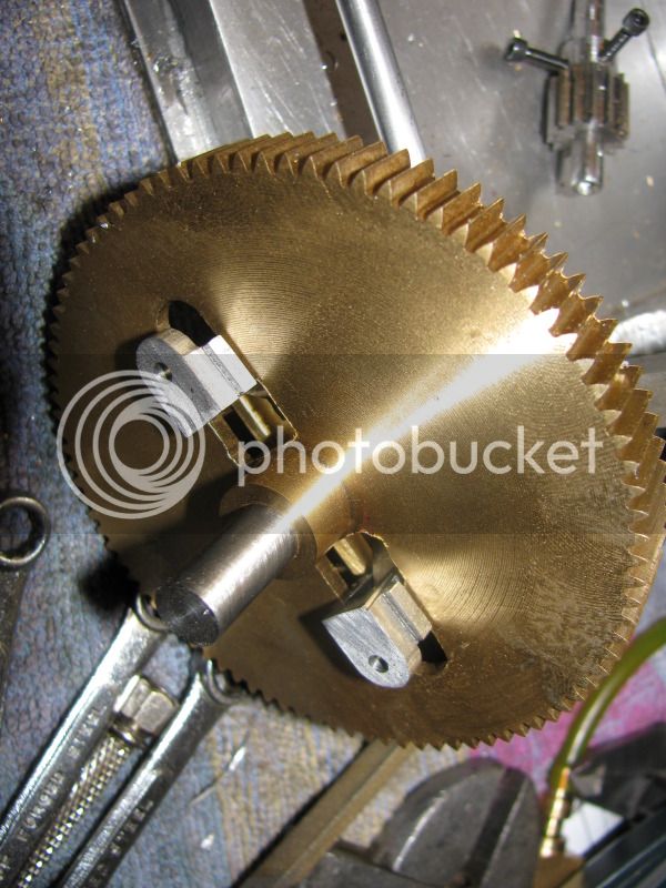
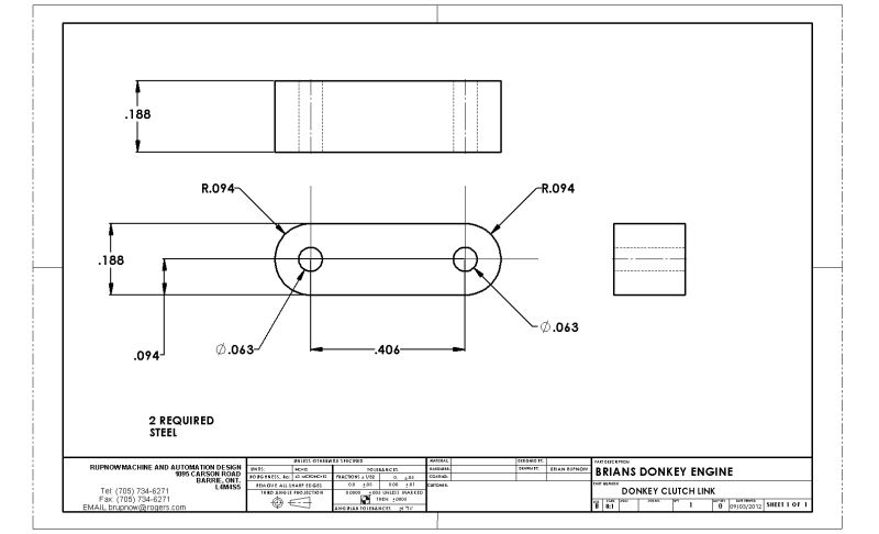
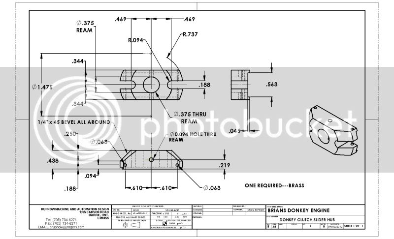
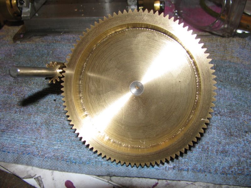
Sticking with my theme of "Tell the truth even when it shows you're a dummy"----I went ahead and made the 12 tooth gear this afternoon. When I went to make it, I see that my charts call for a number 8 cutter. Damn---Thats weird!!! I haven't got a number 8 cutter. My cutters only go up to number 7.---Oh well, we'll use the number 7 cutter anyways---it will probably be close enough. Made the blank and machined the gear. Now, lets do a little math and calculate the center distance between the gears and we'll make a mounting block to see how they mesh.---Lets just check the solid model and make sure that the centers I calculated 5 weeks ago are the same. WHOA NELLY--They're not the same!!! Well, I'm not about to go back and change the bearing stands, so we'll use the center distance off the solid model. As you see in the picture---don't mesh worth poop!!! Okay----I'm not that dumb!!! Time to play detective!!! I know the pitch dia. of the large gear. If I take half that away from the center distance on my bearing stands, and multiply the answer by2 that will give me the pitch diameter of the pinion.---well, son of a gun!---Works out perfect for a 14 tooth gear!---And I have the proper cutter and 21 hole plate to make a 14 tooth gear. SOMEWHERE along the way, I got distracted and modelled a 12 tooth gear, but my overall design was based on a 14 tooth gear. No harm--No foul. Now I know why this is called a Donkey engine. I'm a donkey. Tomorrow I'll make a 14 tooth gear.----Brian
BADGEARS001.jpg
 
that 12 tooth gear is not an error..............it is the start of a new project................i myself have tonnes of parts to start new projects ::)

any pictures of the whole gear cutting process ?

chuck
 
Looks great Brian and the 12 tooth will probably come in handy somewhere else. Good on the detective work too !!!

Bill
 
For those of you who asked, both here and on the other forum I post on---I start out by turning a gear blank to size. This has the outer diameter and face width of the finished gear, and the hub has the finished diameter and length. The bore is drilled and reamed while in the same set-up, and then I use Loctite to "glue" a dummy shaft into the bore. This dummy shaft has a countersink in one end to fit the nosepiece of my tailstock which you will see in my mill/rotary table set-up.
14TOOTHGEARBLANK002.jpg
 
The charts which I got with my rotary table and indexing plates, and with my gear cutters call for a 21 hole divider plate and a #7 gear cutter, which you see here mounted on its spindle. If you can see it, the circles of holes on the divider plate are numbered, and the circle of holes closest to the center are stamped 21 which means that is the circle I will be referencing.
PLATEANDGEARCUTTER001.jpg
 
Thanks for that Loctite suggestion, Brian. I usually use a home made mandrel like one of those below for cutting my gears but I like your method, too.

The first abor has a #2 morse taper with a 3/8" draw bolt to hold in place. I use the second arbor with a 4", 4 jaw chuck that fits the spindle thread on my dividing head.

Chuck

Arbor.jpg


arbor2.jpg
 
In this picture the blank mounted on the 1/4" arbor is held in the chuck attached to the rotary table. The tailstock is supporting the outboard end of the shaft to keep it from deflecting while being cut. The gear is mounted on the mill spindle arbor and set at the correct center height. That brass spacer you see between the gear blank and the chuck jaws is exactly that----a spacer. I have never cut a steel gear before, and I didn't want the pressure of the cutting action to slide the gear blank back on the arbor. The blank is held on its arbor with Loctite, which seems to be sufficient holding adhesion to keep the blank from moving. The 21 hole divider plate is mounted on the rotary table, and the sector arms are set to 9 holes. Note that means 9 visible holes plus the hole that the locator pin is in.
DONKEYGEARS001.jpg

DONKEYGEARS002.jpg

DONKEYGEARS003.jpg
 
Brian

You have encouraged me to do my own gears next time. I have everything except the most important thing - the gear cutters. Obviously mine will be metric.

Vince
 
I have to build two of these sliding clutch links today, and they look problematic. However, they are small. I think I will make one long piece with the correct profile, then part off the two pieces I need. they have to fit and run smoothly in two slots that I cut in my big brass winch gear.
CLUTCHOUTERSLIDERLINK.jpg
 
Teaser Indeed!

I just gotta say that the cost of the brass was worth it in appearance.

This whole project gets more interesting every time I look at it.

--ShopShoe
 
My God---I hate making teeny weeny parts. Especially when they are made out of steel!!! Now if I had an hours creative filing time in on that big brass gear, I'd get those suckers fitted up. Then there are two even smaller pieces to connect them to the sliding collar. However, Jerry did it. And if a Floridian can do it, then darn, a Canuck should be able to.
TINYCLUTCHPARTS002.jpg
 
nice looking gear brian and i for one have NO doubt you will make this whole bag of tricks work and look great.

if as you say "idle hands are the devils work shop" then i guess you must be the purist saint among us cause you hands NEVER seem to be idle. :bow:

chuck the sick canuck
 
Itsy bitsy, teeny weeny, yellow polka dot---Donkey clutch parts!!! They work, and they seem to work very well. There is a world of "frigging" to get everything working freely and not bind, but once they are freed up, they work great. In the one shot showing the back side you can see the slider blocks that attach to the hardwood clutch shoes. I'm not going boldly where no man has gone before here. Captain Jerry had this mostly all worked out months ago.---But then again, he's got a captive Donkey in his back yard that he can run out and measure. I have only ever seen one of these critters in my life, and that was a number of years ago at Algonquin Park in Ontario. Foldks tell me ther is one about half a mile from my house over at the Simcoe County Museum, but I haven't been over to see it. I am rapidly closing in on the point where I have to build my winch drum and external clutch housing.
DONKEYCLUTCHPARTS001.jpg

DONKEYCLUTCHPARTS002.jpg

DONKEYCLUTCHPARTS003.jpg
 
In the middle of all this steam engine foolery, I just installed a new keyboard that seems to be incredibly small, although it is the "standard" model. When I first started to use computers about 15 years ago, I bought one of those big "ergonomic" keyboards, because I have huge hands and fingers. It has finally given up the ghost so I am using this standard keyboard now. Of course it doesn't seem as bad now, since I've had 15 years to practice where my fingers go!! ;D ;D
 
Back
Top