Brian Builds the Kerzel Hit and Miss I.C.

Home Model Engine Machinist Forum

Help Support Home Model Engine Machinist Forum:

This site may earn a commission from merchant affiliate links, including eBay, Amazon, and others.
Chuck---Just cheap Chinese brazed carbide boring tools. I don't get a good finish with them either. I bore close to final size and then ream with an HSS reamer like the one in the picture.
 
Brian, you gotsta' get you a coaster or something instead of your prints! Now how are you going to get those rings out? :big: :big: :big:

BC1
Jim
 
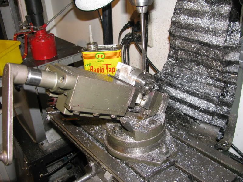
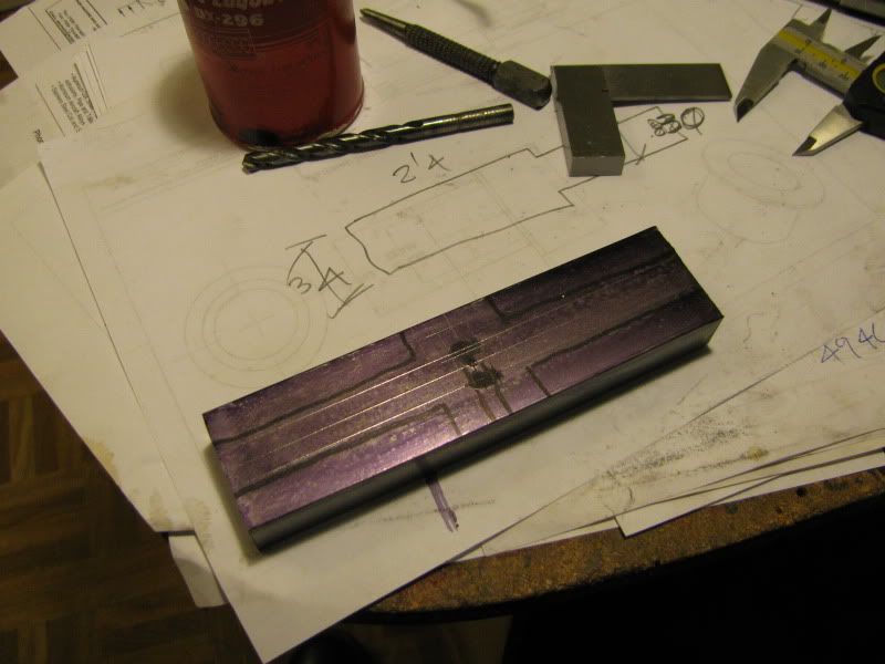
Bearcar---You're right. The whole friggin world gets to see what a slob I am!!! That corner of my desk suffers a lot of indignities. When I'm working on "real work" its my reference desk. When I'm building something for myself, it acts as a catch all, and most of my pictures are taken right there because I have a goose-neck lamp mounted directly above it. When I am working for hours on end at my computer, my big old tomcat gets lonely so he jumps up and sleeps there while I'm working.----Just have to watch the old bugger though, because he loves to chew up my erasors. He's the only cat I've ever seen with a rubber fetish. The wife got a new pair of flip-flop rubber sandals last year and the cat Eat one of them. I'm not too concerned about the coffee stains on the prints. Those are the original drawings by Kerzel that I downloaded from his website and used to build my 3D models of the engine. When I go to actually machine a part, I create new drawings for myself based on my 3D models, because the dimensions I need are not always the same as the dimensions Kerzel provides. Thanks for checking in.---Brian
 
Tonights offering to the machining Gods---A set of crankshaft bearings. a rather blurry picture, but you get the idea. Machined from 660 bearing bronze. Nothing exotic here. Again, they are drilled and reamed to 3/8" diameter. After permanent installation in the engine I will line-ream them to the finished bore of 7/16".
CRANKSHAFTBEARINGS001.jpg
 
That is looking fantastic Brian, i've been away a few days and you've made loads of progress! :bow:

Will be watching this one for sure.

Nick
 
Well, the bolt pattern in the cylinder head matches the tapped holes in the cylinder/water jacket body.---thats always a good sign----now I'm off to downtown to buy some super duper hi temp silicone and get the cylinder liner pressed into place.---And yes, I still have to drill the intake and exhaust ports in the cylinder head.
CYLINDERHEADONENGINE001.jpg

CYLINDERHEADONENGINE003.jpg
 
Here we are, drilling and reaming the ports into the cylinder head. This is the one area where my "Tilt a Whirl" vice really shines. There are probably many other good ways to perform these angular set-ups which I require occasionally, but for my purposes this vice is just great.
portsintocylinderhead001.jpg
 
The cylinder liner is installed!!! Have to admit though, I scared myself on this one. I bought a tube of high temp silicone gasket maker, coated the i.d. of the water jacket, set it up on my anvil (I don't have a hydraulic press) and set a peice of 1" dia. brass with a 3/4" register turned on one end of it into the end of the cylinder liner to act as a drive bushing, and layed into it with my 4 pound hammer. I had about .003" interferance fit. About half way in, it decided "Thats it!!! I'm not going any farther!!!"---Now what????----Well, in for a penny, in for a pound. Went over and picked up the 8 pound sledge hammer. That did the trick. I'm not sure if the liner totally bottomed out on the back of the register or not, but I didn't want to destroy anything so I quit. Its setting in my vice right now with as much pressure as I dared to put on my 3" vice without busting it, to see if it will go in any farther ot not---I'll let it set "under pressure" for a couple of hours and see if it goes in any farther. According to all the measurements I took before hand, there should be about 0.10" of cylinder liner extending past the cylinder head side of the water jacket. I measured about .038 after it was assembled. This is not really a big deal. The engine will work just as well with a bit more cyl. stuck out at that end as it would without.
cyllinerinstalled001.jpg

cyllinerinstalled002.jpg
 
That was too much interferance fit. I've been machining for 2 years now, and I find that I always machine fits one of two ways. Either just a bit too big--(As in the current case) or too damn small, which means throwing the part away and starting over. I knew that was too much interferance, but I didn't want to chance turning off .002" and ruining the part. I wasn't too concerned, because it was stainless steel going into aluminum with some slippery old silicone sealer between the two. The bore did close up about .0005. I ran the reamer thru again and that fixed it.
 
I have a tough time with interference fits as well. I do have a 20 ton hydraulic press that can be mighty persuasive, but I've had to discard more than one part because it was either too big or too small. I usually like to heat the outer part first so it makes getting the two parts together easier.

Chuck
 
HI all i can say is ooooooooooooooooooooooooooooooo thats brill
 
Should have quit while I was ahead.--I may have just made a complete "balls-up" of the one peice crankshaft. I layed it out carefully, marked where to cut it, began cutting it---almost had the offending side cut away---then realized I was cutting away the wrong side!!!! I stopped before I had completely cut it away, and hopefully left enough "meat" on it that I can still save it. I won't know for shure untill tomorrow. Its not a disaster---I bought a length of material twice as long as I needed. Tomorrow I'm going to weld on a short peice of stock to fit between the chuck jaws and act as a drive key, because there is nowhere to put a lathe dog on this thing. The part which I almost cut away has to have the centers in it to turn the con rod journal. Then it does get cut away. Ah, Hell---I've worked enough today!!!!
crankshaftmachining002.jpg

crankshaftmachining003.jpg
 
Sounds like you need to take a day off Brian. Get away from it for a bit. Those types of mistakes get made way too easily when one is either in a hurry or is getting tired or both. Especially for someone such as yourself that *knows better*, now "go to your room young man". Boy don't that make me sound just like a mother? ;D

Hope you are able to recover from that slip up, I'm sure you will. Take some good pics along the way, I'd like to witness your progress.


BC1
Jim
 
You're not the first to make that particular mistake, and certainly not the last, either. Hope you can save it. Looks like you've got just enough left on there if you take really light cuts. Maybe superglue a washer or shim in there to temporarily reinforce it?
 
Pat J said:
Spot weld it in a couple of places.
You can cut it again after you finish.

Pat J

Took the words right out of my mouth. :bow:

Best Regards
Bob
 
This morning we're back in business. One of the off-cuts from the crankshaft body is welded to one of the bits that will eventually be cut away, and extends out past the end to fit between two chuck jaws to act as a drive key.
crankshaftwelded001.jpg
 
Con rod journal is finished and "on Spec". A lot of breath holding and sphincster clenching, but so far, so good!!!
machiningcrankshaft-2002.jpg

machiningcrankshaft-2001.jpg
 
Well done Brian, I'm sure your butt muscles did get a good workout today. I have been dreading doing this step on my engine and it makes me very nervous even thinking about it and then when I see pictures of it having been done it's even worse. You know, kind of like going to the dentist with a toothache and all it turns out to be wrong is a bit of popcorn kernal under the gumline. :big:

BC1
Kim
 
After I cut away the extra material which had the centers drilled in the ends to enable turning the connecting rod journal, this is what I'm left with. Now I will put a bolt and a couple of washers and a nut through the center slot to keep the crankshaft from collapsing under pressure and mount the crank in the second set of centers to turn the rest of it.
crankshaftmachining-3002.jpg

crankshaftmachining-3001.jpg
 
Now I have a question. Which 'side' (hand) are you going to machine on? That is the end that is closest to the chuck leaving the end towards the tailstock rough cut and then change ends around so the newly machined end is toward the tailstock and machine the rough cut end in the same manner? Or will you merely leave the piece in place between centers and work both sides without disturbing the piece? hmmm. I would think the former would be the best approach as it would place the least stress upon the opening, even with the strain relief steps being taken. I've never made a one-piece crank so am watching intently as you proceed. Thanks.

BC1
Jim
 

Latest posts

Back
Top