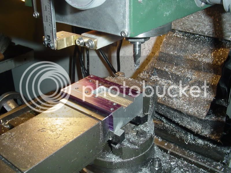
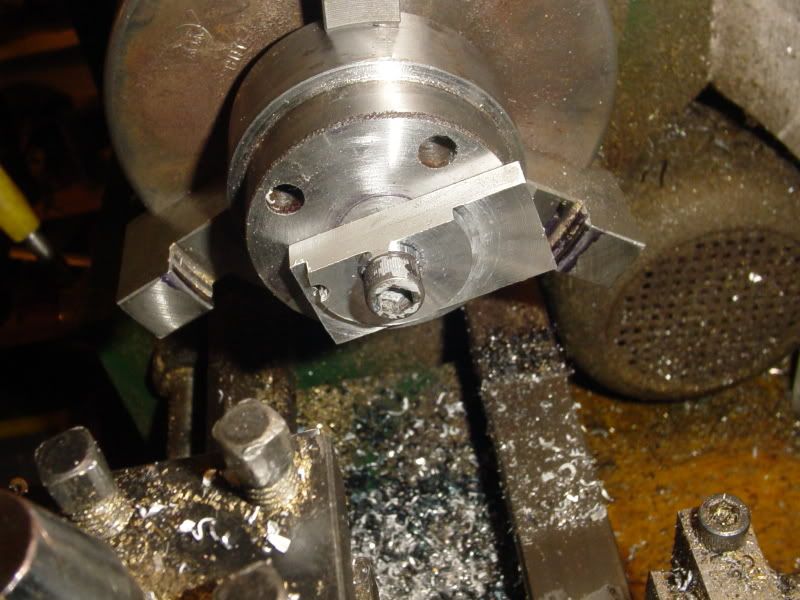
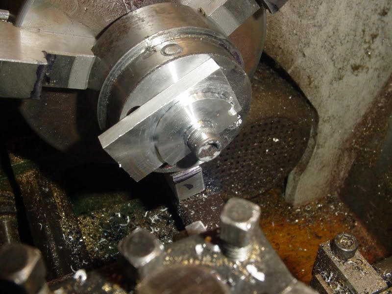
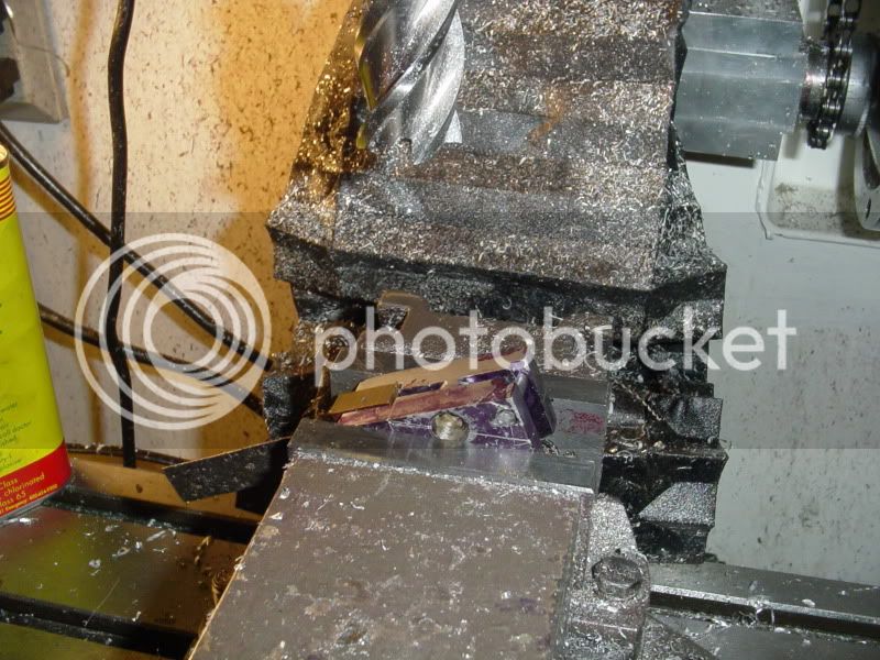
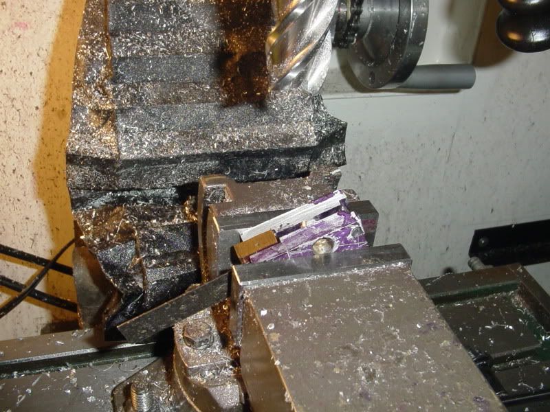
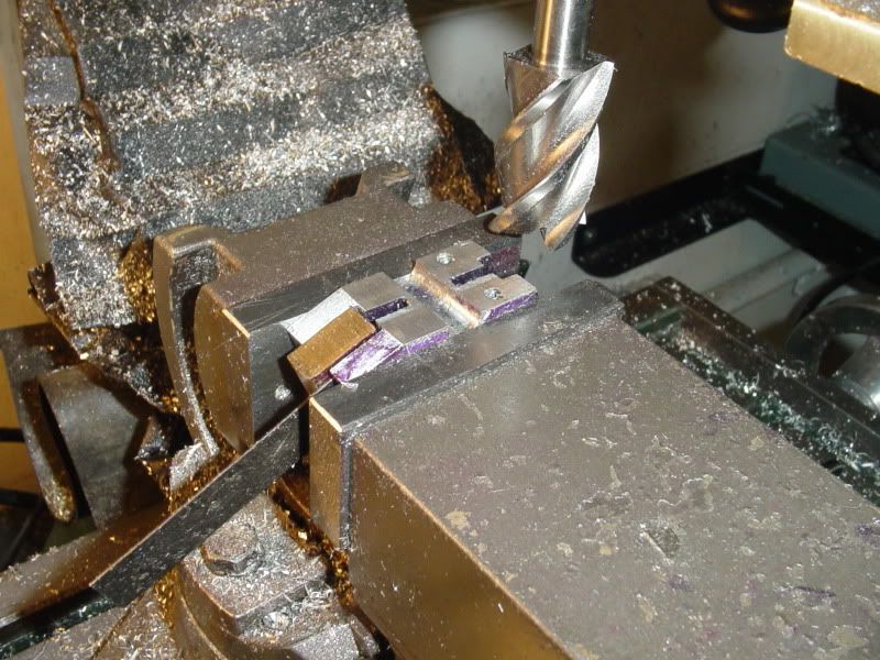
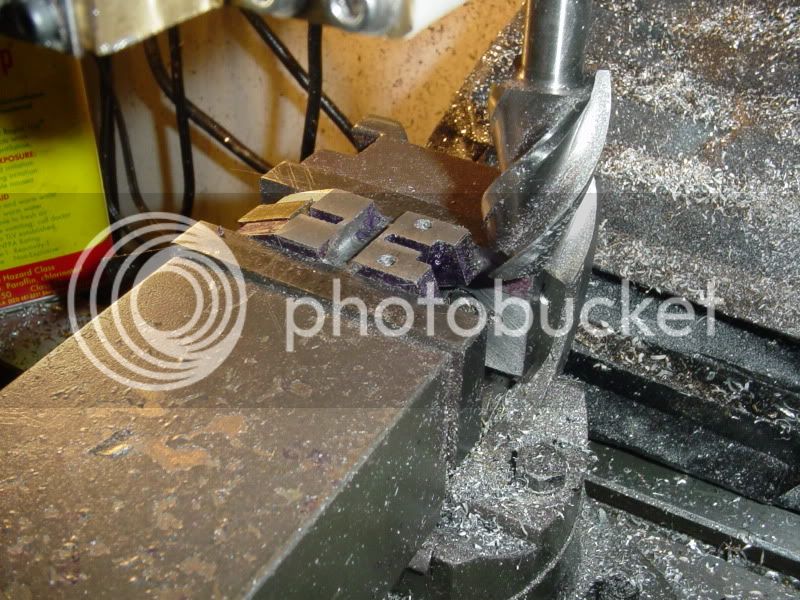
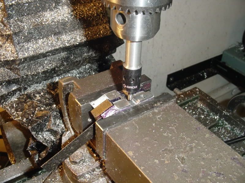
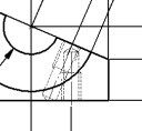
Well---Let me see---the cutter is listed as being a 5/32" radius cutter. So--If I bring the end of the tool down to touch the top of my part, set the vertical travel dial indicator to "0", then advance the quill 5/64" that should put the center of the curved cutting face in line with the top surface of the part. Then I move the part in untill it just "kisses" the edge of the cutter, and feed in 0.010 increments untill the resulting radius is where it "Looks good". Take note of the total amount that I fed the part into the cutter, and use that figure to set up cuts on the other 3 sides.---am I close????