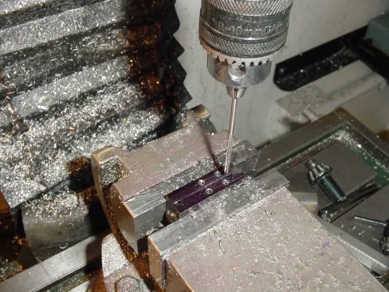
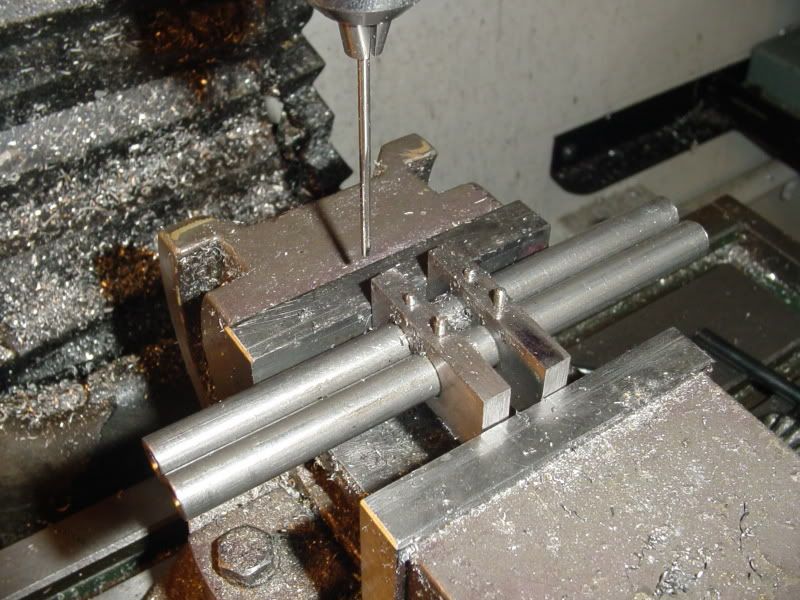
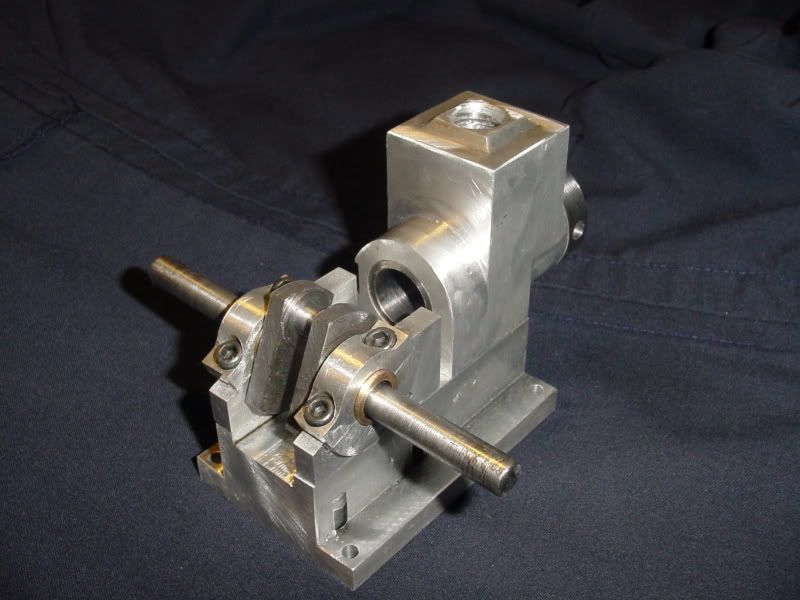
So there we have the crankshaft installed. It looks good, but as I had feared, the crankshaft is no good. The fact that my tailstock had moved out of alignment sometime during or before the crankshaft machining operation has given me a crankshaft that has a terrific wobble in it. This is dissapointing, but its not an unfixable disaster. I will use this crank to set everything else up on the engine, and make another crankshaft closer to the end of the game.
") but you'll have a jolly old time trying to fit that on the 0.375" crankshaft.
but you'll have a jolly old time trying to fit that on the 0.375" crankshaft.