I need to find some good literature on cam timing as it applies to small, single cylinder, low speed i.c. engines. Book that takes a practical, real world approach to lap, lead, etcetera. Any good suggestions?--Remember, I am in Canada, so probably an American publication would be more convenient to access.

You are using an out of date browser. It may not display this or other websites correctly.
You should upgrade or use an alternative browser.
You should upgrade or use an alternative browser.
Better Insight into Cam Timing
- Thread starter Brian Rupnow
- Start date


Help Support Home Model Engine Machinist Forum:
This site may earn a commission from merchant affiliate
links, including eBay, Amazon, and others.
Lakc
Well-Known Member
Such a book would be very helpful, but I fear it does not exist. At least, not one that specifically targeted.
What will exist, are various SAE papers on the subject, but not easy to find unless you have access to library that has them. There have been a lot of recent papers regarding variable cam timing. Some good info can be gleaned from various aftermarket camshaft grinders and performance sites.
What I think you and I are both looking for is out there, but mostly its "reading between the lines", and not spelled out too conveniently.
Cam timing is only part of the equation. The way I learned it long ago was air+fuel=power, and thus more air+more fuel=even more power. The fuel has to make it perfectly mixed with the air and not just running along the intake runner. That means you need to keep the velocity up and eliminate bends, dropouts, and stagnation areas in the intake side. Exhaust side is treated likewise, as not to hinder the intake and possibly to obtain some useful scavenging effect from the negative pressure pulse created as the mass of exhaust gas uses its momentum and pulls away from the closed exhaust valve. All that requires a lot of math involving the mass of air and piston speed, and calculating pressure differentials across an orifice (valve area) and thermodynamic effects of expansion from combustion.
Even more fun is calculating the clearances involved in our tiny engines and watching how they affect the actual cam timing as we can build them.
- Joined
- Jun 24, 2010
- Messages
- 2,361
- Reaction score
- 931
Two posts here on HMEM if it helps.
http://www.homemodelenginemachinist.com/f12/designing-engine-21808/
http://www.homemodelenginemachinist.com/f26/valve-timing-4-stroke-glow-17093/
I have the Malcom book & its kind of guide-lines & ratio based. I really should validate & upload my Excel tool one day, might be useful. I've also done just simple comparison tabulations across analog engines. Some parameters 'scale' to FS engines, others not, probably to be expected.
My own personal take-way is there is actually quite a bit of variation amongst model designers even among roughly similar engines classes. Now what that actually means is another matter. Maybe the models are tolerant of variation. Or maybe there are some good runners in the mix & others less so. Hard to know unless you've seen them run. For my own purposes, I was tending towards copycat-ing parameters of commercial (RC) engines, only because that's what I'm seeking to replicate & I know firsthand they work for a living
There is a classic book that is really worth a read called 'Tuning for Speed' by our very famous Ozzie Phill Irving. First Published in 1948 and now in its 6th edition ISBN 0 908031 29 7. Do not be put off by the word speed in the title as Phill clearly shows how different parameter changes affect the performance of the engine. He has also a book on two strokes but I do not have a copy as I was only interested in 4 strokes. If you want to approach more towards the theoretical ''The High-Speed Internal Combustion Engine" by Sir Harry Richardo and JGG Hempson enables some insight of engines.
Cheers,
Kerry from Oz
Cheers,
Kerry from Oz
Last edited:
Try this web site
Gives a lot of timing figures right back to Model T fords
http://www.tildentechnologies.com/Cams/CamHistory.html
Ralph
Gives a lot of timing figures right back to Model T fords
http://www.tildentechnologies.com/Cams/CamHistory.html
Ralph
I have just ordered "Miniature Internal Combustion Engines" by Malcolm Stride. I am not certain that this is the book I really want, as some of my questions regarding cam timing have risen from the engine I so recently built which was designed by Malcolm stride.--However, the man seems to "know his stuff" around small engines, and I found his overall design to be very complete and accurate and well executed. I had trouble reading some parts of his drawings, but I think that can be put down more to differences in drawing styles than any gross inaccuracies in his drawings. My birthday is coming up very soon, and my wife asked me this morning what I wanted for a birthday gift. I thought that this book would be informative and perhaps shed some light on the aspects of small engine design that I am still rather vague about. George Britnell---You should write a book yourself if you haven't already. I found more information in your post than I have been able to find in many reference books I have looked at.---Brian
Swifty
Well-Known Member
Hi Brian, I found Malcolm's book well worth it, but you are correct regarding his drawing style, it leaves a lot to be desired. It's very easy to be confused with his drawn parts as there seems to be no difference between hidden lines and solid lines, you really have to be very careful.
Paul.
Paul.
I have just read a truly amazing excerpt from a book called "Model 4-stroke Petrol Engines - Designing, Running, Building" by Len Mason, which answers many of the questions I had about cam timing. I was so impressed by his clear explanation of the subject that I immediately did a Google search, and found that this book is still in print and is available from Amazon.com. The only problem is that the price of a new book is over $200 Canadian. However, (and fortunately), they also sell used copies, and have them available at much lower prices, depending of course on their condition. I have ordered a "good used" copy for about $45 plus shipping and tax, which brings it to about $61. I now have two books on order, and have completely blown my budget for "summer technical reading".---Trust me--It is hard to explain to your wife why, when she has just ordered a book for your birthday about "them little motors", why you have suddenly spent $61 on a book about "exactly the same thing"!!!
- Joined
- May 27, 2010
- Messages
- 2,999
- Reaction score
- 1,171
Hi Brian, I found Malcolm's book well worth it, but you are correct regarding his drawing style, it leaves a lot to be desired. It's very easy to be confused with his drawn parts as there seems to be no difference between hidden lines and solid lines, you really have to be very careful.
Paul.
Gus easy and willing victim.:wall::hDe:
Good reason why I am taking it easy. No more goofs.
Lakc
Well-Known Member
You cant have too many books.
The fun thing about technical reading is it brings to mind more questions to be solved by more books!
The fun thing about technical reading is it brings to mind more questions to be solved by more books!
I purchased the book "Miniature internal Combustion Engines" by Malcolm Stride published by Crowood Press in Wiltshire U.K. It is an excellent book on small engine design, with easy to understand articles covering all aspects of small internal combustion engines, including a great section on cam design. The book is a hardcover, of 175 pages, with many colour pictures and technical drawings. I highly recommend it to anyone interested in model i.c. engines. I believe I paid about $40 Canadian for it, including the shipping charges. You can contact Crowood Press at [email protected] I purchased my copy through the Canadian book store Chapters-Indigo.---Brian
Cam design is a black art, and few share their secrets. Not sure of the differences in scale between models and Harleys, but if you go to this below link at Andrews Products and click on any of the "VIEW" links you can download their Harley cam specs including timing, duration, lift and what applications they suit.
It may give you some insight into what factors affect what results.
http://www.andrewsproducts.com/motorcycle-parts/2013motorcycle-catalog
Of course, Harleys have whopping great low-revving cylinders, so if you google around and find similar info for small Hondas it might suit. (Their 250cc 6-cylinder racer of the 60s was little more than model size anyways!)
I have just received and read through the second book I had ordered, "Model Four Cycle Gasoline Engines" by L.C. Mason. Although it is quite a good book, it doesn't give any more information than the book by Malcolm Stride, and doesn't have as many pages, illustrations, nor technical drawings, and was written in 1976, quite a lot earlier than Malcolm Stride's book, (although very little has changed in the world of small model engines since then.)---I really don't think it is worth anywhere's near the $200 Canadian that is asked for a new copy of it on Amazon.com So--a summary of what I have read/learned. I am quite sure I knew about 90% of the information contained in these two books. They have cleared up some of the mystery surrounding cam design, and a bit of the size relationships between various engine components. The rest of the stuff, I knew already----but then I should. I have worked as a mechanical design engineer for the past 49 years, been involved in hot-rod building and drag racing for almost as long, and have built 10 steam engines and seven i.c. engines. They will certainly be valuable reference books to add to my ever growing stack of "resource literature" about this marvelous hobby.---Brian
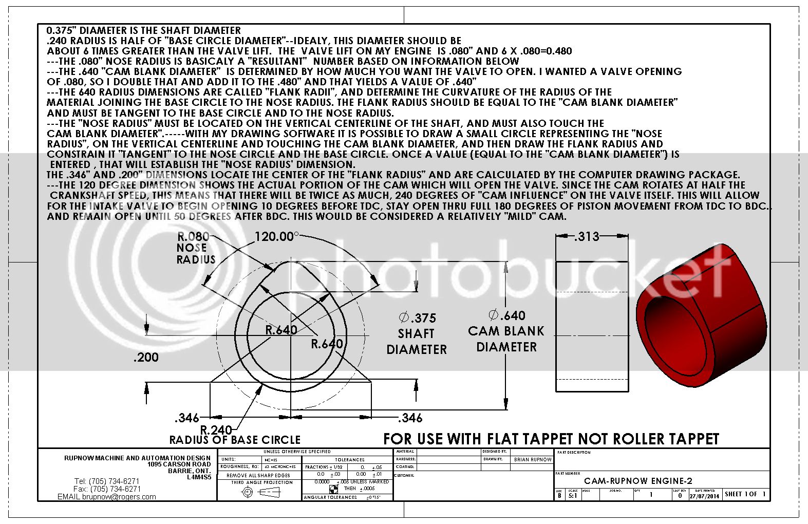
So--After multiple readings of both books, I have began to comprehend the basics of cam design.I hope you are able to read the drawing posted here, because it will explain some of the theory/mystery behind the actual design of a cam itself. The timing of cams is a whole different issue, and all I will say about it here is that a relatively mild cam for a 4 cycle i.c. engine, running at relatively low rpm (500 to 2500 RPM) would begin to open the intake valve approximately 10 degrees before the piston reached top dead center on the exhaust stroke, stay open while the piston travels from top dead center to bottom dead center on the intake stroke , and remain open until it closes at about 50 degrees after the piston has started upwards on the compression stroke. I know that sounds like a lot , 240 degrees of total cam influence, but remember that when talking about piston movement in relationship to degrees of crankshaft rotation, the piston travels relatively short distances during the 30 degrees either side of top or bottom dead center, and travels most of its total distance to be covered during the 120 remaining degrees in half a crankshaft rotation. In the drawing, I picked the 3/8" shaft diameter. That is a somewhat arbitrary number, but must remain smaller than the "base circle diameter". The .080" of valve lift is a dimension that is calculated by determining that the volume of space between the face of the valve and the seat when the valve is fully open should be equal to the volume of a cross section taken through the intake runner leading to the valve. If anyone takes exception to the information I have given, or wants to ask a question, I will be glad to discuss it. Remember--Although I have been designing mechanical devices for 49 years now, this entire cam design thing is relatively new to me too.---Brian Rupnow.

Last edited:
- Joined
- Dec 31, 2010
- Messages
- 783
- Reaction score
- 195
Hi Brian:
Don't forget to figure in some valve lash. A small lash of even 5thou will make a big difference in the open / close timing and therefore duration etc of the lobe.
Evidenced by the sometimes huge difference between the "advertised" and "actual" durations quoted for full sized cams. Hot rod guys like choose and brag that they have a high duration cam but when they read the "actual" duration (after the necessary 50thou valve lash is added in for solid lifter cams) they are sometimes quite disappointed.
If you know someone with a CNC mill you might want to try our grinding program to grind your lobes or just run your numbers through it to see if they are valid.
http://gcam.lucasemail.org/
http://www.homemodelenginemachinist.com/showthread.php?t=21127
https://groups.yahoo.com/neo/groups/GCam_CNC/info
Dave Sage (Mississauga)
Dave--the valve lash on these little engines is very small, about .005" is all that is required. If I was going to factor that into the calculation for the valve, what, exactly, would it be added to?---Brian
- Joined
- Jul 16, 2007
- Messages
- 2,986
- Reaction score
- 1,055
Brian,
The clearance will change the timing events. Lets say the timing events were calculated with no clearance and the valves opened or closed at X degrees. This would give the cam lobe a certain profile. Now if we add .003 (this is the amount I use for miniature engines) then the cam would have to rotate more to take up that clearance. When you first started talking about cam design I went back into some of my engine cam specs, one flat tappet and one roller and laid out the change in timing by eliminating the clearance and even on these small engines it changed quite a bit. Would that hurt the performance of the engine, I doubt it, but it will change it.
gbritnell
Swifty
Well-Known Member
Brian, I reread you posting #15 where you have posted the cam drawing. After reading the following posts about valve clearance / lash, I can see that it is a real headache to design a cam to allow for the correct opening angles whilst allowing for the lash. Yes, we are only making model engines here and not formulae 1 engines, but it can see as others say, that .005" clearance will make a big difference to the valve timing / duration. I may fire up the CAD later today and play around with cam profiles to see if there is an easy way out, just for my own interest.
Paul.
Paul.
From the two books that I have recently purchased and read, I don't believe that the allowance for clearance/valve lash is really a big deal. It may be if you are building a hi performance engine, but for little one cylinder runners that basically set on a corner of the workshop table and are started up once in a while "for fun", I just don't think it matters. It is a parameter that we should be aware of, and if we are designing an engine for a high performance application it should perhaps be taken into consideration. My question still stands though---if I did take it into consideration, then what number would it effect in the calculation and layout of the cam?---Brian
Similar threads
- Replies
- 44
- Views
- 8K
- Replies
- 199
- Views
- 62K
- Replies
- 8
- Views
- 4K