Bazmak-A Model Horizontal Shaper

Home Model Engine Machinist Forum

Help Support Home Model Engine Machinist Forum:

This site may earn a commission from merchant affiliate links, including eBay, Amazon, and others.
<iframe width="560" height="315" src="https://www.youtube.com/embed/uSVno9DQn80" frameborder="0" allowfullscreen></iframe>
I have made a video bit ameateurist and long and struggled to upload to photobucket so went to Utube.Hope it works
 
Okay Baz--I volunteer. send the stuff you need done on cad to brupnowATrogers.com and I will do them up as .dwg (Autocad) and as .pdf files so anybody without cad can open them.---Brian Rupnow
 
You only need part of what you posted. I wrapped code flags agound the following so you can see it without executing it. If you you click "share" under the video it will put this part in a box and depending on what browser you are using it may copy it to your clip board so you can paste it. Thwn paste this into your post.
Gail in NM
Code:
<iframe width="560" height="315"  src="https://www.youtube.com/embed/uSVno9DQn80" frameborder="0"  allowfullscreen></iframe>

https://www.youtube.com/embed/uSVno9DQn80
And the result is:
https://www.youtube.com/embed/uSVno9DQn80
 
Very interesting. That adjustable eccentric and ratchet and pawl feed is the same system I used on the carriage advance for the model sawmill I built a few years ago.---Brian
 
Thank you Gail the video is now up hope I can do it myself next time
Thank you Brian,i will make a start with details and a build sequence
It will take time so will do it in batches if anyone wants to make a start
it will be helpful.Will email some sketches in the next few days and we can try to make your usual professional job of it.Yes the pawl and rachet is nice and simple,as used by the author but to a better scale.Any suggestions on a drive source,i would like a small motor that could be mounted local.I have seen references to stepper motors will google and investigate.Would like to fit a pulley to the driveshaft and leave a small extension to fit and remove the the large handwheel for ease of turning over
 
Hi Gus,i made it basically to plans in model engineer but scaled up x 1.5
Some details are mine and simplified.I would like to make the plans available if there is enough interest,BUT,although all my working life as a draftsman I cannot use autocad.I would be prepared to put pencil to paper and scan up sketchs etc if someone would volunteer to convert to computer drgs,details etc and arrangements and make available to anyone.Any offers please post
We could make it a team build/draw ????


Hi Baz,

I did manual drafting for 11 years. Was supposed to pickup CAD. Never did. I was promoted and went into another dept doing something else but drafting.
But I plan to. TurboCad was disappointing. Somehow Genuine CAD is cheaper across the border in Malaysia. Not pirated.

After the Howell V-2, its no more engines for 12 months. Have a long list of tools to DIY.

Take Care.
 
sme here Gus,i retired early and didn't want the long learning curve
as I struggled with computers anyway.Would have liked to but
decided it wasn't worth the effort
 
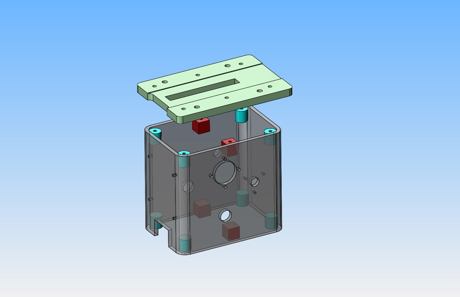
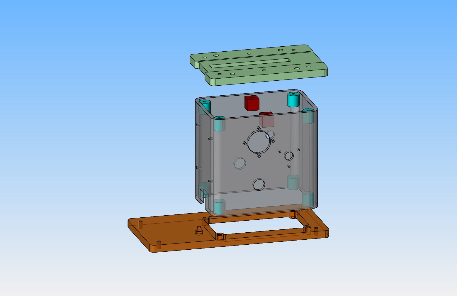
I got this far and realized a few things. the slot in the top plate which you dimensioned as being 165 mm long can not possibly be that long---please send corrected slot length. One of the holes in the right side body has no pattern of threaded holes shown around it, and neither of the holes on the left side of the body has a pattern of threaded holes around it. Is this really so or should they have tapped hole patterns around all three holes. The "cut out" at the bottom of the rectangular tube has no dimensions on it so I just showed a "best guess" sized "cut out" I need the correct dimensions for that "cut out" ---And finally, many of the dimensions on the bottom plate were "cut off" on the drawing you sent me. Please resend the detail of that bottom plate.---Brian
 
Very Impressive. I will have to keep a look out for the plans.

Colin
 
A lovely piece of work there Baz, it is always refreshing to see something being made that can be used rather than just looked at.

I was given a brand new good quality MIG welder a few years ago. I am very proficient (or used to be) at gas and stick welding (unfortunately, gave them away many years ago), but can't seem to get good results with the MIG.
I have a few things like yours to construct, but until I can get this welding under my belt, I will just have to sit back and drool over wonderful constructions such as yours.

John
 
Hi John,i served my time as a welder/sheetmetal worker but never used mig
until I was a lot older and then only at industrial level.I am now only a competent welder and find the small home stick welder adequate for most things.Unless you are doing a lot of welding then mig at home can be too complicated particular the finicky equipment/gas etc
 
H Brian,glad to see your on the ball that's why I sent some details immediately so we can sort out potential problems early.The scanned image cuts off the edges and I tried to send too much info on one page will try to rectify next time
Please use the photos in the thread to help clarify things.Will send the missing dims.Meanwhile to answer your questions
1-The top slot is 110mm the o/a plt length is 165mm
2-Lh side 16dia no fixings(fit bush and E clip)
3-Rh side 12dia with fixings for brg housing
4- 16dia both sides for lever no fixings (fit bushes and E clips)
5-Cutout shown as 25w x 20h to front view
Will send rescan of page edges for missing dims
I am trying to measure items and avoid stripping the unit down as yet
as I am making adjustments and a maybe a better video
I will send details hopefully in the order I made them refer photos and thread
Note the sq tapped insert are only welded to the top not the bottom
6 fixings to top and 4 to bottom.Regards Barry
 
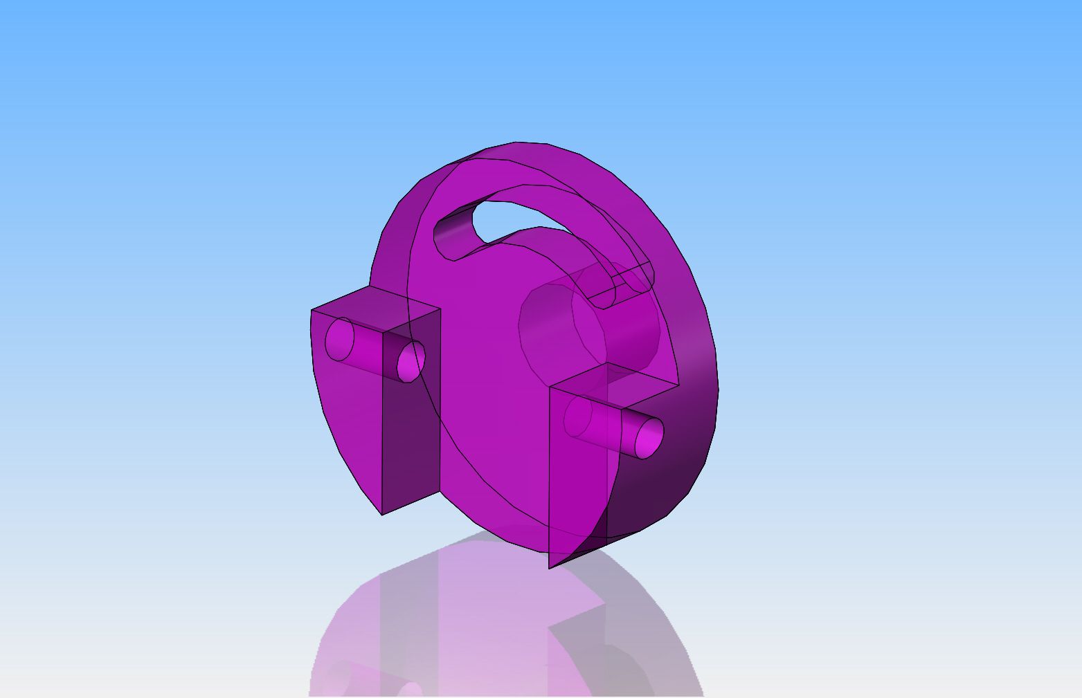
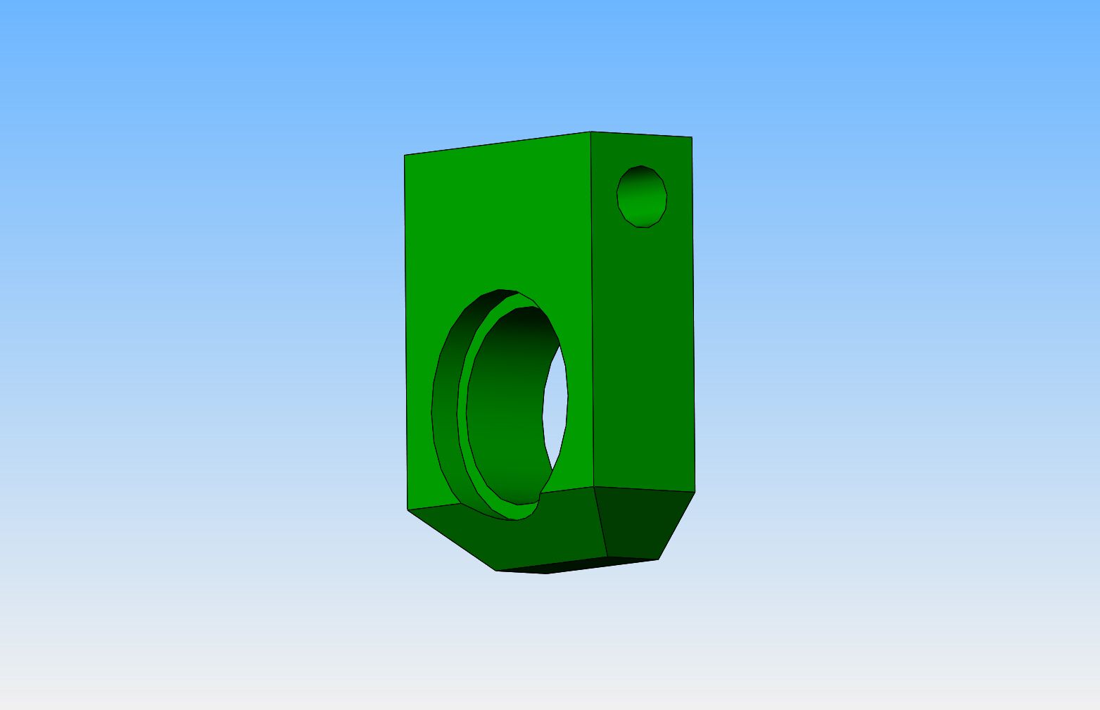
Barry--Here is a redo of the assembly --I have corrected the slot in the top plate to be 110 mm long. I have removed the square blocks from the bottom of the rectangular tube main body. I have changed the cut-out in the front of the rectangular tube to 25 wide x 20 high. I still don`t have the information on the bottom plate thickness nor overall length, the location and size of the countersunk hole, nor the four thru holes in the baseplate that anchor it to the tabletop. The new scans you sent me are still cutting that info off the bottom plate, and I don`t think you have a thickness anywhere on the drawing. I will work later this weekend on the other parts you sent me.---Brian---EDIT--Baseplate updated
 
Last edited:
Hi Brian, to the right says bottom plt 10 thk,250x120mm.The 4 tapped holes are typ 15mm from all 4 edges and can be m6/8 to suit feet.Dont know how much is cut off at your end.Your GA shows the bseplt needs turning around
the longer end to the front. regards barry
 
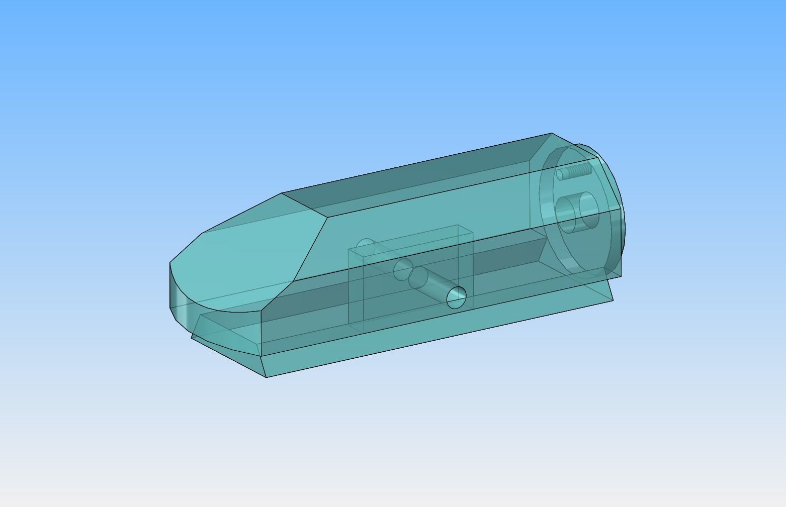
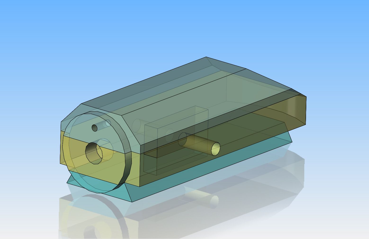
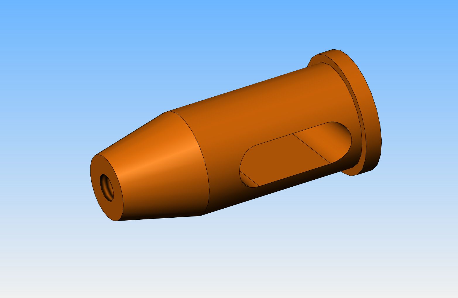
Do you want the shaper to be detailed as being machined from one solid piece or a built-up assembly from 3 separate pieces. If you want the dovetail to be cut from a separate piece and bolted in place, you have to give me locations for the M6 `dovetail fixings` and how do you attach that 58 mm dia. round piece on the end. Also, what diameter is the cross-hole that runs thru the slot. There is no way to machine a slot as shown on your sketch.
 
Hi Brian,i think it is better to assume we make in 3 pieces and bolt together
Please read the thread on making the ram.The items are bolted together
and the end diameter is turned in the lathe The slot can be milled thru the dovetail plt and the lower and upper sections separately Will do some more details and keep them smaller and simpler.Will also start a parts list to be
improved/ongoing
 

Latest posts

Back
Top