arnoldb
Well-Known Member
- Joined
- Apr 8, 2009
- Messages
- 1,792
- Reaction score
- 12
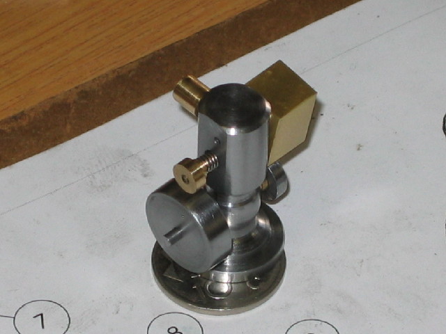
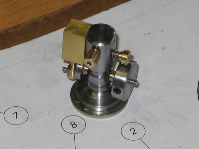
Having spent quite a bit of time on making tools of late, I decided to build another engine for a change.
Elmer's Tiny has been on my list for quite a couple of months - so time to get it done")
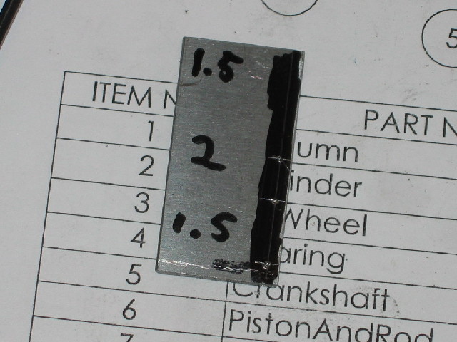
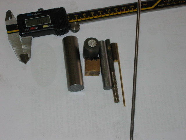
First I collected a couple of off-cuts together - some pieces of printer shaft, a bit of 6mm brass from a ball-valve and so on:
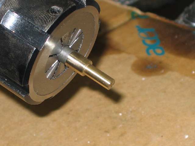
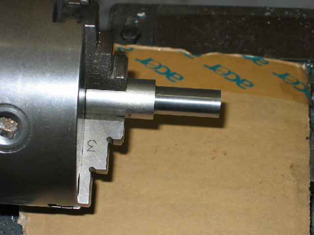
Started with the column. Piece of printer shaft chucked up, faced at the end, and the length marked as per Elmer's instructions:
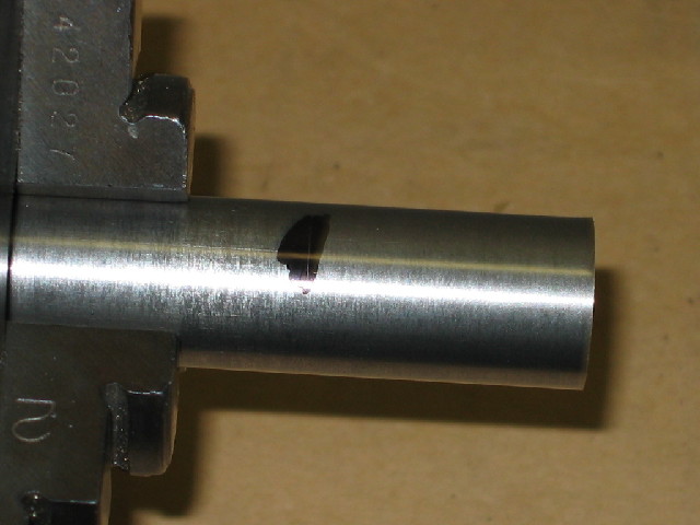
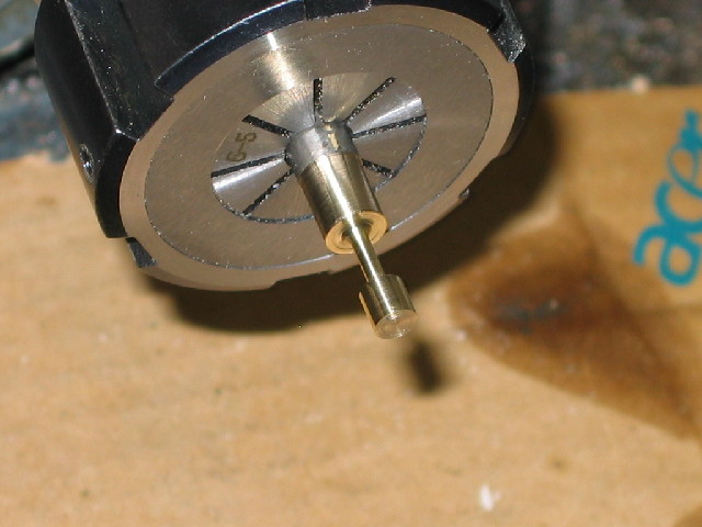
Then turned down to the top of the column's diameter:
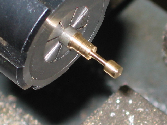
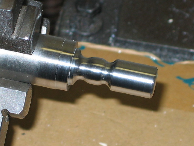
And did the turning on the bottom part of the column and some cleaning up with emery paper. It's obvious I still need some practice at free-hand ornamental turning...:
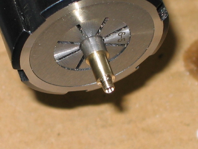
After this, I parted off the column - this printer shaft is very nice to machine, and parting was a breeze:
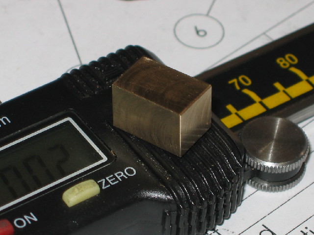
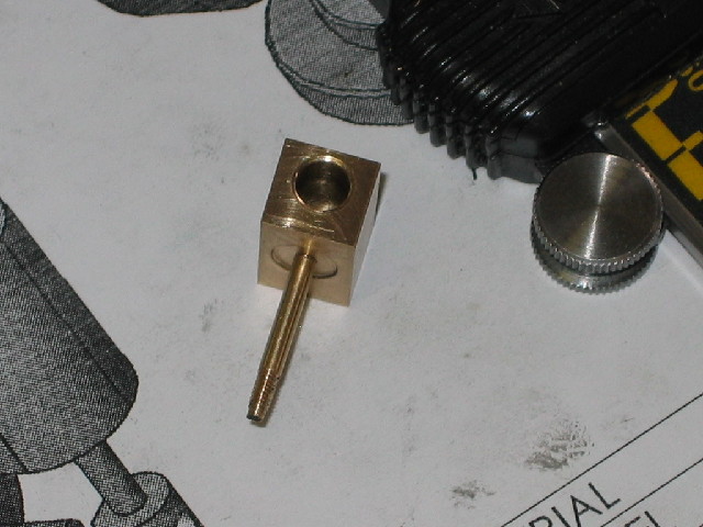
Next up was the bearing; I nearly made it too small on outer diameter; that's why it's pretty rough on the surface... I'll just polish up the parts that will be visible later on:
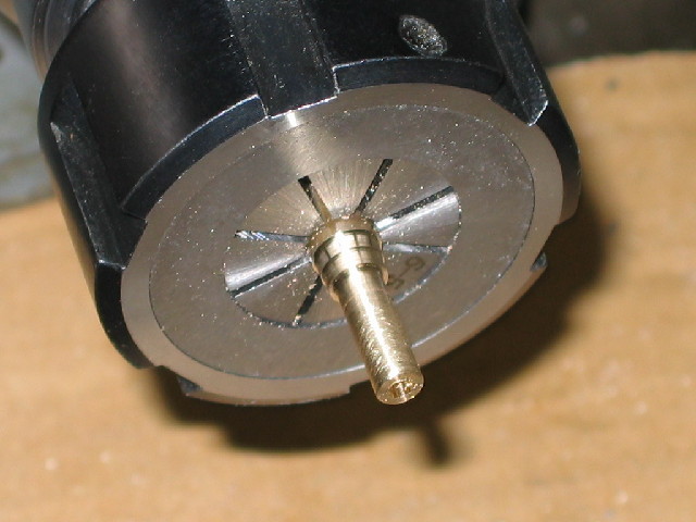
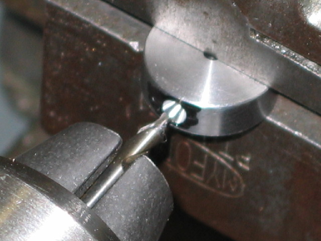
The crank followed; I chucked up a bit of 10mm silver steel, and just marked the center with my smallest center drill. Coloured up a part of the surface with a permanent marker, and used a compass to mark the crank-pin distance and center-punched:
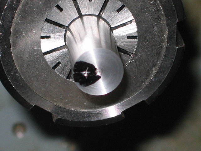
Having done the marking-out, I turned the crank web to size, and drilled and reamed the center for the main shaft.
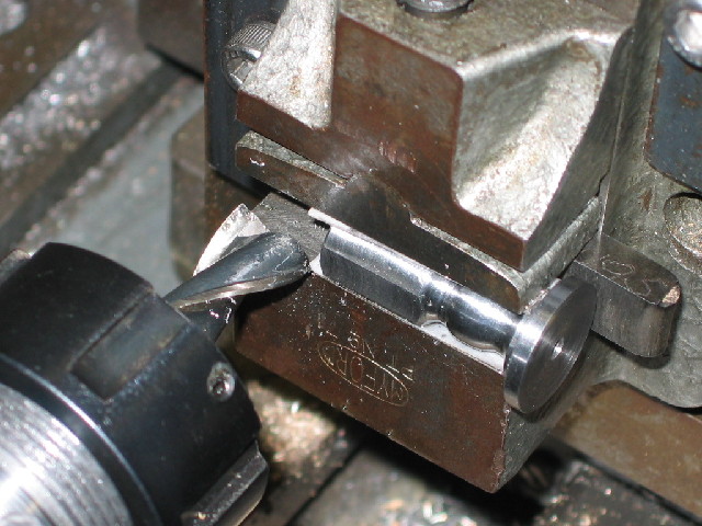
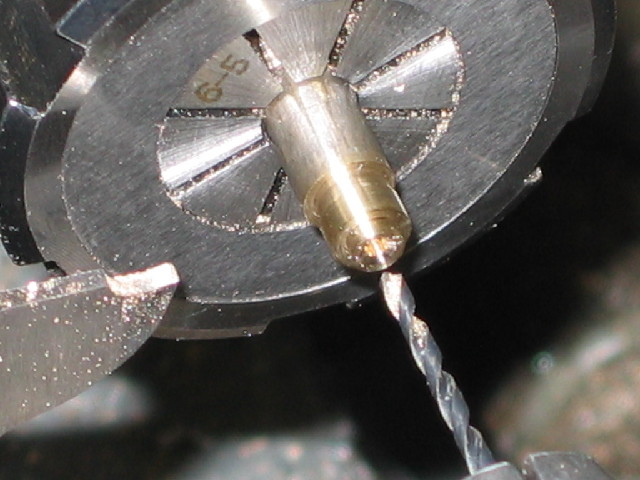
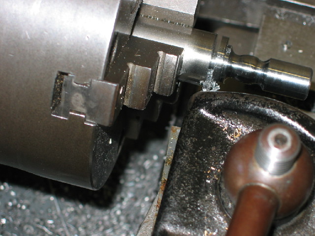
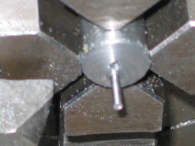
Then transferred the lot to the 4-jaw chuck, and set it up off-center to drill for the crank pin. At this point some perverse whim took a hold of me, and I ended up actually turning the crank pin as part of the web (apologies for the blurry photo):
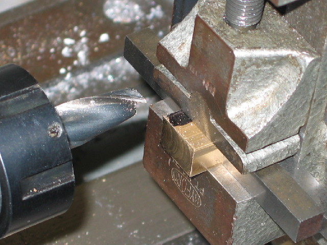
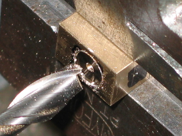
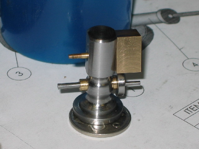
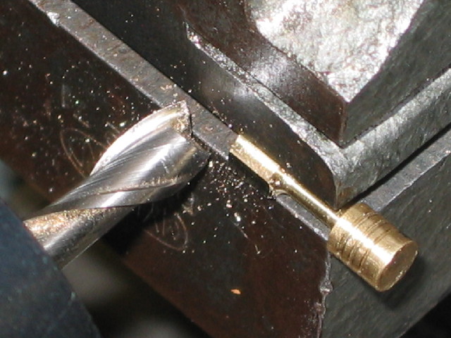
Before having to set up the lathe for milling, I also made the pivot pin from some 2mm brazing rod. Deviating from Elmer's specifications here, I threaded both sides; one end short for screwing into the cylinder, and the other for taking a nut rather than the cross-drilled retaining pin called for in the plans.
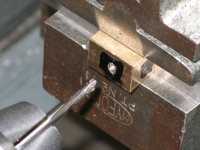
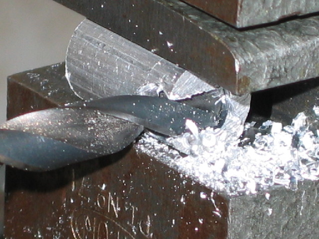
Then I made a d-bit to be used for finishing the cylinder and found a spring from a car tire-valve that should work as pivot spring. One thing I forgot to make is the "measuring pin" for locating the port holes; that I'll do tomorrow before setting up for milling. The crank web and shaft were also loctited together to cure overnight
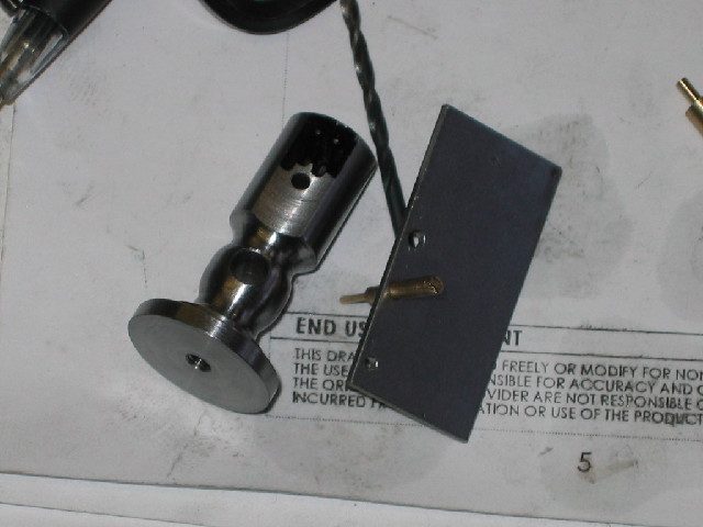
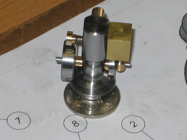
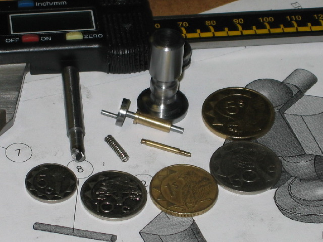
Last photo to show today's bunch-o'-bits (and a couple of coins to keep "certain members" happy )
I wanted to be, and would have been, further along - after all I am on holiday, but was repeatedly interrupted with crisis-calls from my bosses at work :wall:
Kind Regards, Arnold
Elmer's Tiny has been on my list for quite a couple of months - so time to get it done
First I collected a couple of off-cuts together - some pieces of printer shaft, a bit of 6mm brass from a ball-valve and so on:
Started with the column. Piece of printer shaft chucked up, faced at the end, and the length marked as per Elmer's instructions:
Then turned down to the top of the column's diameter:
And did the turning on the bottom part of the column and some cleaning up with emery paper. It's obvious I still need some practice at free-hand ornamental turning...:
After this, I parted off the column - this printer shaft is very nice to machine, and parting was a breeze:
Next up was the bearing; I nearly made it too small on outer diameter; that's why it's pretty rough on the surface... I'll just polish up the parts that will be visible later on:
The crank followed; I chucked up a bit of 10mm silver steel, and just marked the center with my smallest center drill. Coloured up a part of the surface with a permanent marker, and used a compass to mark the crank-pin distance and center-punched:
Having done the marking-out, I turned the crank web to size, and drilled and reamed the center for the main shaft.
Then transferred the lot to the 4-jaw chuck, and set it up off-center to drill for the crank pin. At this point some perverse whim took a hold of me, and I ended up actually turning the crank pin as part of the web (apologies for the blurry photo):
Before having to set up the lathe for milling, I also made the pivot pin from some 2mm brazing rod. Deviating from Elmer's specifications here, I threaded both sides; one end short for screwing into the cylinder, and the other for taking a nut rather than the cross-drilled retaining pin called for in the plans.
Then I made a d-bit to be used for finishing the cylinder and found a spring from a car tire-valve that should work as pivot spring. One thing I forgot to make is the "measuring pin" for locating the port holes; that I'll do tomorrow before setting up for milling. The crank web and shaft were also loctited together to cure overnight
Last photo to show today's bunch-o'-bits (and a couple of coins to keep "certain members" happy
)
I wanted to be, and would have been, further along - after all I am on holiday, but was repeatedly interrupted with crisis-calls from my bosses at work :wall:
Kind Regards, Arnold