Arnold's take on Elmer's Grasshopper

Home Model Engine Machinist Forum

Help Support Home Model Engine Machinist Forum:

This site may earn a commission from merchant affiliate links, including eBay, Amazon, and others.
Very nice work Arnold, it is coming along very well indeed, and very nice write up as well.

I get real homesick watching all you lads doing things like this, it is so long since I have managed to build an engine.

Yet again, just watching as your projects come along is almost as good as the real thing.

Bogs
 
arnoldb said:
it's slowly starting to look like something

It sure is...and something nice too.

You went through the soldering step with some confidence there. I've yet to do any but my time is coming. ;D
 
Been enjoying your build of Elmer's grasshopper! Looks like your coming along very well. Really great pictures and information.

Dave
 
Hi Arnold

Looking really good now. Just one question if I may, what do you pickle steel parts in??

Cheers

Rich
 
Bogs, thank you very much ;D - And my best wishes that your personal circumstances change for the better soon; it would be great to see you turning out another engine. And thank you very much for all the valuable assistance you give to everyone in need :bow: - it does not go unnoticed!

Thanks Carl :) - There's nothing like a boiler build to boost confidence in silver soldering stickpoke :big:; it gets easier all the time!

Dave, Thanks :) - I try, but I keep forgetting some essential things to show though...

Thank you Rich ;D I don't do pickling before hand like with brass & copper; just an hour or so in some citric acid after soldering together to get rid of the flux and most of the thick oxide layer from the heat... It may not be the best method though. One HAVE to wash the parts immediately when it comes out, otherwise it will rust like mad in a matter of minutes. Also, the metal comes out dull grey, but that's easily cleaned off with some scotch brite. Another funny that I noticed with this particular lot - (I used the same pickle that I did when I built Fred's boiler) - was that there was a copper layer forming on the steel... Maybe it's time I made up some new pickle :big:.

Well, some more bits done today; all in brass :D

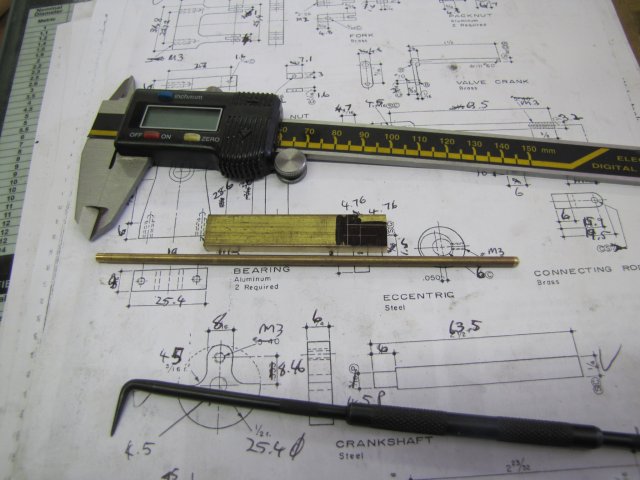
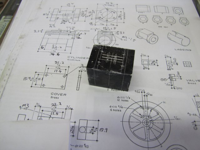
I got some stock together to make up the con rod:
normal_IMG_0975.JPG


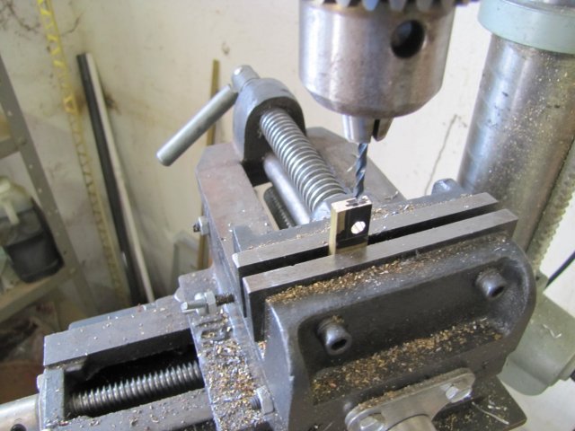
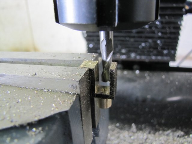
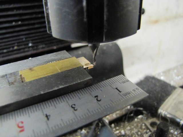
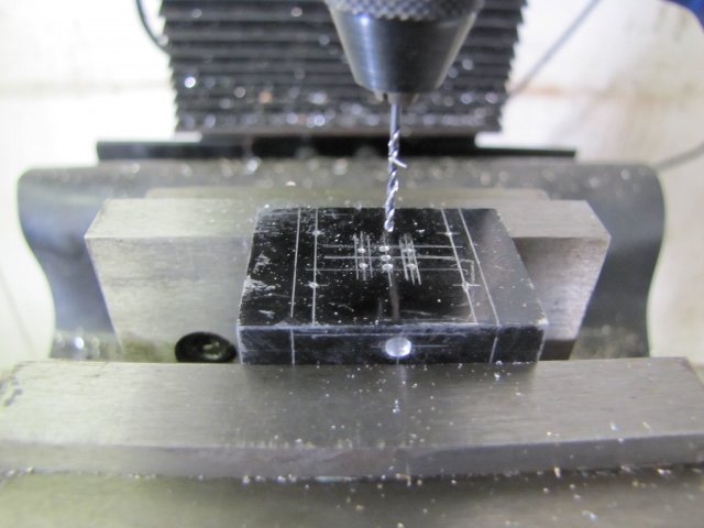
Next, drilled the 4.5mm hole for the crank screw; fortunately, my 4.5mm drill is a bit blunt already, so it does not grab while drilling the brass. Just a light and slow feed, and it drills a very acceptable round hole with smooth sides. Then the hole for the con rod shaft followed; workpiece aligned parallel to the drill bit (none of my squares would fit, so I used that bodge) then clamped. Drill press depth stop set to stop at the appropriate depth, and drilled the 3.2mm hole:
normal_IMG_0976.JPG


The hole ended up ever so slightly under size, so the rod would not fit easily; I ended up with an unexpected tight press fit. I would have silver soldered this joint, and, in retrospect I should have for looks, but I just used electronics solder to join the pieces. Here the parts before soldering; the solder just need to fill and join in the chamfer:
normal_IMG_0977.JPG


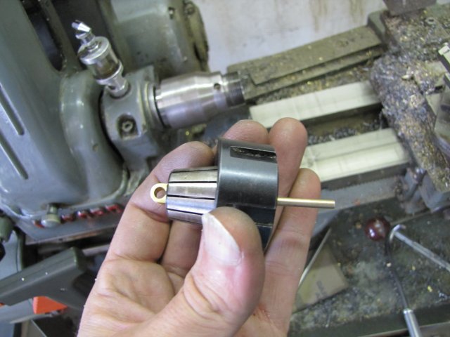
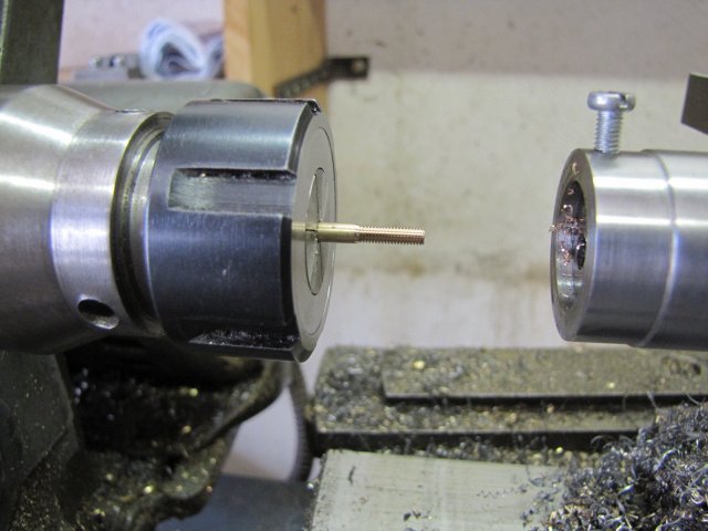
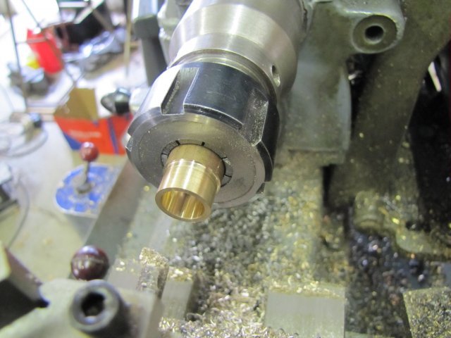
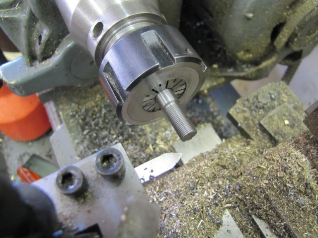
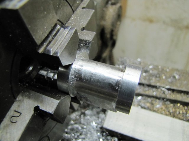
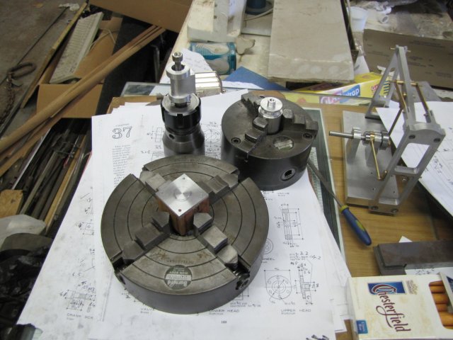
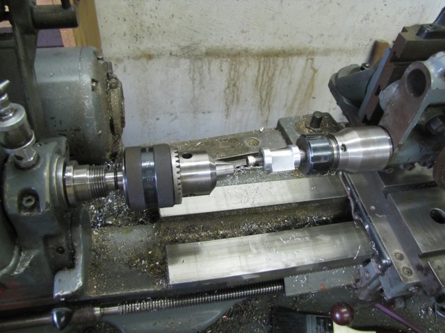
Next, I fit the con rod assembly in reverse into the lathe collet chuck, so that I could turn down and thread the fork end:
normal_IMG_0978.JPG

(Have I ever mentioned how pleased I am that I made that collet chuck for the lathe and how useful it is ? ;D)

Turned down to 3mm and threaded up:
normal_IMG_0980.JPG


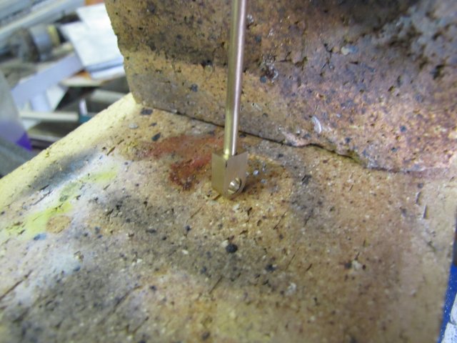
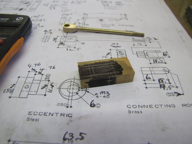
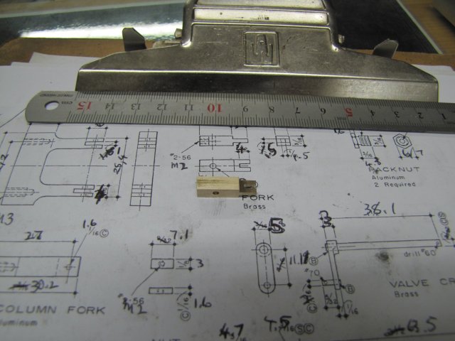
The fork laid out on a block of brass - and in the background the ring of gray solder visible on the con rod.... :
normal_IMG_0981.JPG


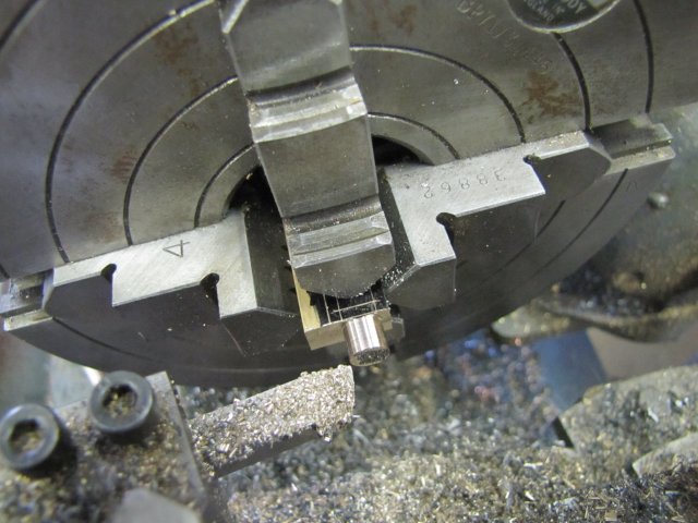
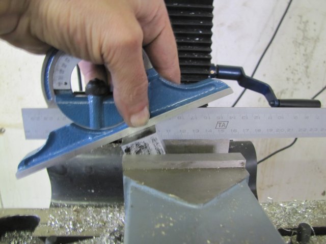
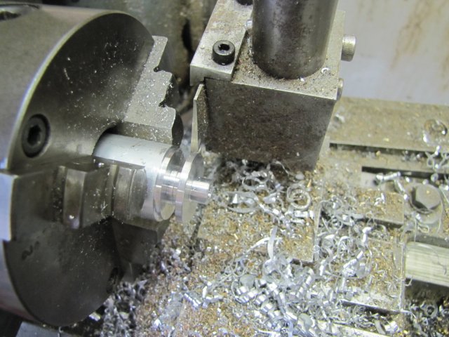
Turning down the round part of the fork in the 4-jaw. The "excess" bit of material pictured on the left of the stock was left there on purpose:
normal_IMG_0984.JPG


The reason for the excess bit mentioned above. The fork is a bit fiddly to clamp - so to mill out the center bit, and have a sort-of good grip, I left that as clamping space:
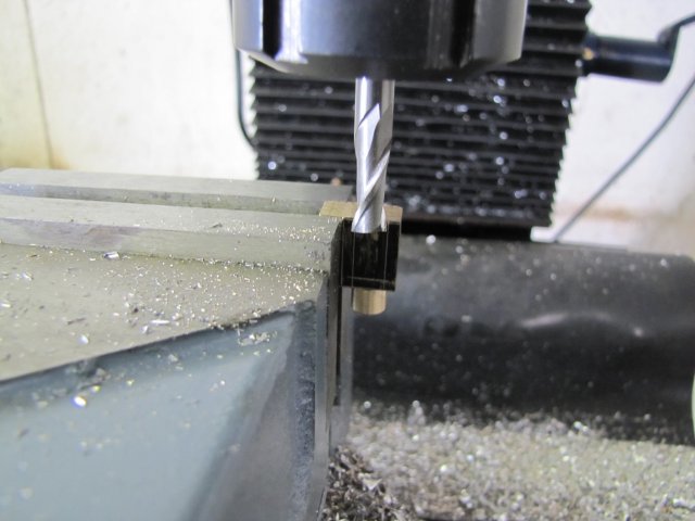
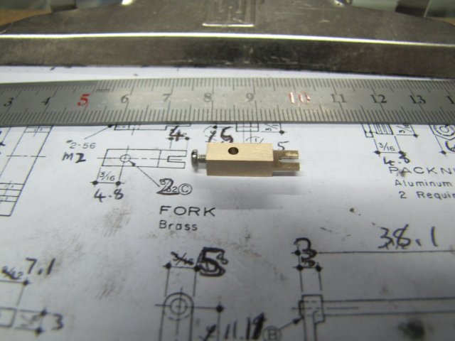
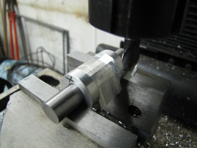
normal_IMG_0985.JPG


Fork nearly done:
normal_IMG_0986.JPG

After this photo was taken, I clamped it horizontally and milled away the excess.

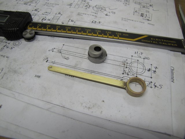
Next, I turned some 8mm hex rod down to make the crank screw. 6mm would have been much better, so I might end up re-making or sizing down the crank screw.
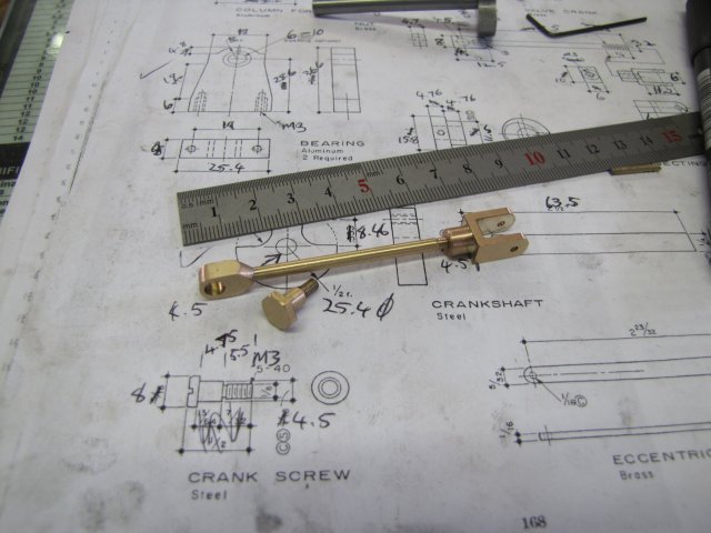
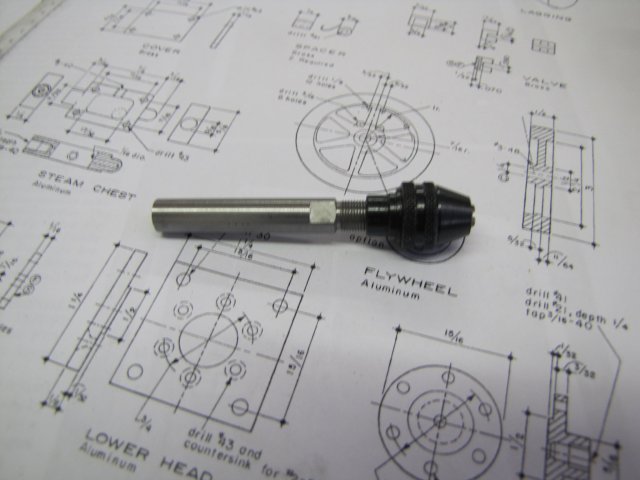
The finished con rod and (for now) crank screw:
normal_IMG_0988.JPG


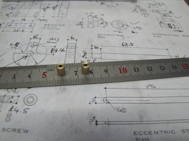
I also made the spacers that are needed for the beam links:
normal_IMG_0989.JPG


At this point I nearly stopped for the day... Some inner devil told me I could do another bit though, so I did.
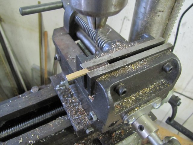
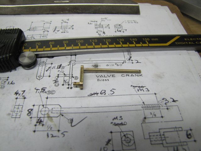
The valve crank arm is in the same page of the plans as the connecting rod, so I started on that; a strip of 2mm thick brass plate sawed from stock, and just filed to width (takes the same time to set up the mill as it does to do manually, and I need the exercise :big:) - it needed two 2mm holes drilled for for the shaft and pin:
normal_IMG_0990.JPG


I then drilled 1mm holes through near the end of some 2mm brazing rod bits (I expected failure here, but it went surprisingly well; - I 'll post photos on how I did it in a later update), and used electrical solder to solder them on the valve crank arm. After some cleanup, it looks like this:
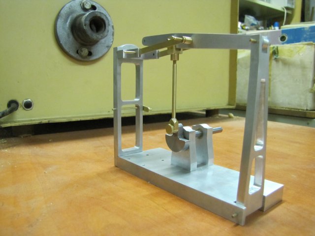
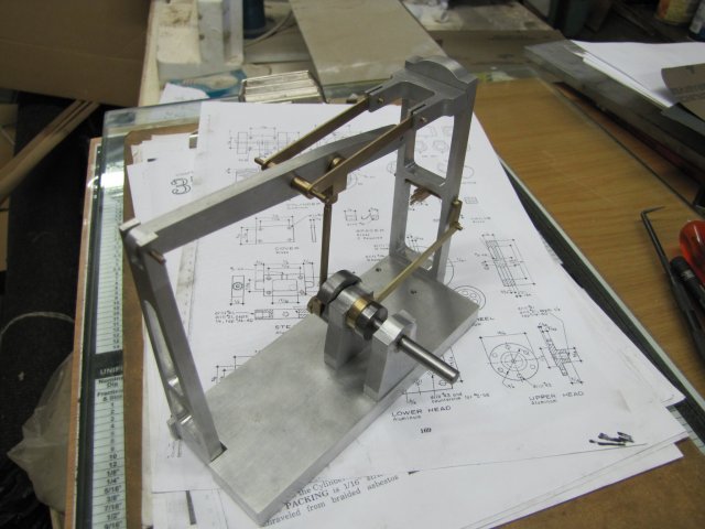
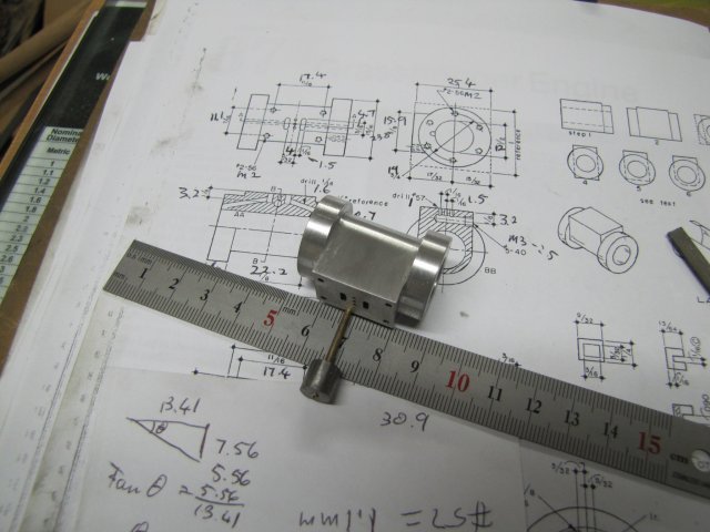
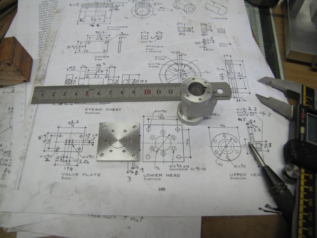
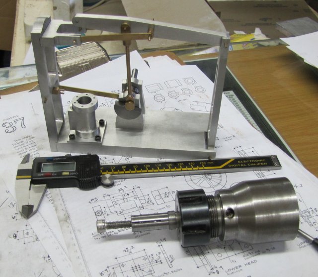
normal_IMG_0992.JPG


An assembly shot:
normal_IMG_0993.JPG


Regards, Arnold
 
One HAVE to wash the parts immediately when it comes out, otherwise it will rust like mad in a matter of minutes. Also, the metal comes out dull grey, but that's easily cleaned off with some scotch brite. Another funny that I noticed with this particular lot - (I used the same pickle that I did when I built Fred's boiler) - was that there was a copper layer forming on the steel..

Phosphoric acid is a better proposition for steel, and in fact, I use it for all my pickling. It seems to set up some sort of protective barrier on the steel BUT it will still deposit that copper on the surface if it's been used for that previously.
 
Excellent job Arnold! Your moving right along, and at a very good pace!

The similarities between many of Elmer's plans start to become evident in the style of certain parts, and can be seen as I watch your build progress.

Elmer's use of similar or identical parts in more than one plan is a style in-itself.

Great looking engine and build. I must have missed this model when I looked over the collection and printed up my choices last year.

-MB

 
The assembly shot shows a lot of progress, Arnold.
You're really good at this stuff!

Dean
 
Your really knocking this stuff out...the engine is looking great!!!
 
Thank you Tel ;D - I think I have some phosphoric acid stashed away; I will dig it out and give that a go on steel parts - and not dunk steel parts in pickle that's been used for copper of brass in future...

MB, thanks ;D - Now you have at least one new project for next season ;) I've browsed through Elmer's plans a lot, and did notice the similarities. It was only when I really went through this one's build instructions and I noticed that he referred to the "addendum" for some tasks like making the cylinder that all became clear. The "addendum" contains a LOT of handy information!

;D Thank you Dean; don't really know if I'm any good, but I'm trying.

Thanks Chris ;D - though this week was a bit slow... I hoped to be a bit further along.

Monday was a public holiday here in Namibia, so I looked forward to a full day in the shop... Alas, that didn't happen, as I spent the whole day helping a friend sort out his computer. So machining-wise, the day was lost, but at least I'll end up with a sheep in the freezer in return.

Tuesday evening, I started on the eccentric strap. Some 16mm brass bar turned down and bored to a smooth and close running fit on the eccentric:
normal_IMG_0998.JPG

That's as far as I got for Tuesday though, as I was interrupted by visitors.

Wednesday, I parted the ring off, and silver soldered a strip of plate to it to form the rest of the strap. I didn't take photos of the process though; was in a bit of a rush. In a nutshell, I filed an approximate rounding in the end of the plate to be joined to the turned ring, then placed the ring flat on a fire brick. Then I supported the plate lying on two washers to get the correct height, and with lots of flux between the ring and plate heated the lot from the ring's inside direction to prevent burning the flux away. A light dab of the silver solder rod, and the joint was a good 'un. Some clean-up later, and this is the result:
normal_IMG_1002.JPG


With some time left in the shop, I looked around for a simple part to make. The fork looked like a good idea, so I started on that.
A straight forward mark-out job in a bit of brass bar, then drilled the 2mm mounting hole in it in the drill press, on to the mill, and milled away the cut-outs to leave the "tang" (for lack of a better term). I bought a 1.5mm slot mill a couple of months ago, but never used it; here I had a prime candidate, so I used it to mill the slot in the "tang". Very carefully; that slot mill is small! :
normal_IMG_1005.JPG


Then I sawed the excess stock off the piece, milled it to final dimensions and started clean-up. While doing the clean up, I noticed something... and placed it on the plans next to it's drawing:
normal_IMG_1006.JPG

:Doh: - the mounting hole is on the wrong axis :wall: That stopped shop for yesterday, and introduced the first booboo of the build.

Today after work, I re-made the fork; a couple of minutes milling and sawing, then a bit of rubbing over emery and the new one was done. Second time around is a LOT quicker then the first...:
normal_IMG_1007.JPG


And finally, the new bits added to the assembly:
normal_IMG_1008.JPG


At least the weekend is getting closer ;D
Regards, Arnold
 
Nice work Arnold. :bow:

Commiserations on the hiccup but at least it was on a small part, my stuff ups usually occur on something big. :-X

Best Regards
Bob
 
but at least I'll end up with a sheep in the freezer in return.

Won't the poor bugger get awfully cold in there?
 
'zakly Ed, over here we bung 'em in the oven for a couple of hours before serving! ;)
 
Sorry to get my giggles at your expense, Arnold, but I laughed out loud when I saw the "forked" part on the print. You're a gem. Glad you got it straightened away.


tel said:
over here we bung 'em in the oven

Man, it really is a completely different language...
 
arnoldb said:
and introduced the first booboo of the build.

Hold on there Arnold...no pessimism please. Might be okay to say 'introduced A booboo' but let's not imply there'll be more. ;D (That's what I do.)

Looking great!
 
Thank you Bob ;D - Those stuff-ups seem to come at random though :p - I think I was lucky this time ;D

Tel, no worries mate; that sheep will have some bits of oryx and ostrich for company; it should feel right at home especially seeing it was quite hot here of late :big: Poor bugger just don't know what's coming up; I'm going to make it meow like a cat on the meat saw ;)

Thanks Ed ;D - It's a pleasure !

:big: - Thank you Dean; I didn't notice that specific connotation until you spoke up ;D - Yup; it's "forked" :big: Glad you're enjoying this ;)

Thank you Zee ;D - I'll hold back on the pessimism; just remember I'm an optimist with limited experience ;D

Back to the build...

Well, not quite. I've been frustrated with the mill's drill chuck capabilities, so I took a bit of time out to sort that out for now.
A bit of 8mm silver steel turned down to 7.1mm and single point threaded with a 60 degree 40 tpi thread:
normal_IMG_1010.JPG


Milled some flats to take a spanner on the shaft, drilled it 4.3mm to a depth of about 40mm and ended up in an adapter to take a Dremel chuck. I can chuck that in the mill's collet chuck (or lathe or drill press ;D) to handle small drills:
normal_IMG_1012.JPG

I promptly broke a 1mm drill with it in the mill when testing; ran that little drill about 15mm down into a scrap of aluminium... Silly me; no "feel" on this, and I didn't stop for some chip clearance, so a lesson learnt for the next bits...

Time for the cylinder. I started off with a block of 25.4mm (1") aluminium square bar. I was surprised when I measured it and found it was in fact 1" bar and not the normal 25mm we get here in Southern Africa. I just faced the one bandsawed end in the 4-jaw chuck to get it square (quick job as it did not need to be centered perfectly), took it out, measured and marked the precise length, and faced the other sawed end to the proper length.
A wipe-over with some permanent marker ink, and a long time to measure out, mark and punch some hole centers later:
normal_IMG_1014.JPG


I first drilled the exhaust port thread hole from the side, then flipped the block to work on the face. Drilling some 1mm holes for the exhaust passages in the block with the spindle I made:
normal_IMG_1015.JPG


Then I milled the slots for the steam ports with a 1.5mm slot mill. Next a tricky bit - setting the block to the angle for drilling the steam passages. I settled on using the reference angle Elmer specifies in the drawings set up on a protractor, and used the protractor on the "top" of each side of the block to set it in the vise:
normal_IMG_1017.JPG

Then, using the 1.5mm end mill, I drilled it about 3mm into the block to provide a starting path for the 1.6mm drill that I used to drill to meet up with the slots milled on the face. Worked a treat :D

In all my previous builds I've shied away from doing rounding over on cylinders... So It was high time. I don't have a rotary table yet (that's my next build!). I thought about ways of mounting the Myford's dividing head to do the job with adequate rigidity on the mill - but that would have involved turning up a split arbor to hold the cylinder block and spacers to mount the DH on the mill (checkmark another tuit), so I ended up doing it with facets milled off the sides. First, I milled the block down like Elmer describes. Then a close-fitting rod through the bore on top of the vise jaws, and mill away a bit at a time with the Y-readings to stop at memorized. After each pass, stop, turn the workpiece a bit & redo ;D :
normal_IMG_1020.JPG


To get rid of the facets, I just chucked the piece up in the lathe (the 4-jaw was still mounted, so just very roughly centered in it), and with a small file I filed away the excess. Start with the piece with one side face up, and with the left hand rotating the chuck and a file in the right hand stroking forward while rotating the chuck, it took very little time at all to get rid of the facets:
normal_IMG_1023.JPG


After filing, I used some progressive strips of sandpaper to get rid of the filing marks. The end result of today's work:
normal_IMG_1024.JPG

I still need to tap the valve box mounting holes, the exhaust port and drill & tap the holes for the cylinder heads.

Regards, Arnold
 
Ah...thank you Arnold.
I have one of those protractors and have yet to use it.
You've now given me some ideas of how to use it.

There sure seems to be a marked difference, not just in your approach, but in your attitude in this build. Must be new found experience. ;D
 
Nice work Arnold you seam to be getting to grips with your new Mill

Have fun

Stew
 
Thank you Carl ;D. I have used the protractor for other things as well; mostly on plate and welding work to get angles. These protractors are not too well known for being entirely accurate though; the better ones cost a fair bit of money. There's definitely a sine bar in my future... Have to save up though! No new-found experience; just additional tools ;D; leaves me with more ways to get a job done, and leaves a bit of time to at least try and improve things like finishes and accuracy ;D.

Thanks Stew ;D - yes, I think I'm getting to grips with the mill; some niggles to overcome, but overall I am very happy with it.

Today's bit:

First up the bottom cylinder head; I only had some 6mm aluminium plate to make it from, so that needed quite a bit of turning down to get to the 3.2mm base size. Just chucking it up on the 4 Jaw didn't seem a good proposition; too fiddly. Being aluminium, I couldn't solder it to anything for support, so I ended up using some brown stuff. A block of wood about the same size as the base (bigger would do as well) just squared up in the 4-jaw:
normal_IMG_1025.JPG


Then I clamped the aluminium plate to the wood block on the square face with a toolmaker's clamp, and drilled tap-size for M3 through the mounting marks right through the plate and wood. I then removed the clamp and opened the 4 holes in the wood to 3mm to pass M3 screws. The holes in the plate was then tapped M3. I ended up with some bolts through the would that I could mount the pate on:
normal_IMG_1026.JPG


Mounted and centered in the 4-jaw chuck:
normal_IMG_1027.JPG


And turned down:
normal_IMG_1028.JPG

I left the whole lot in the chuck; just unscrewed the chuck off the spindle and set aside.

The top cylinder head followed from a bit of 25mm aluminium rod in the 3-jaw chuck. I just turned down, drilled and threaded the front bit according to the plans; the only change is I used M5 for thread. Not wanting to remove the piece because of the extra effort that would then be involved to get the cylinder boss machined concentric, I did that with a parting tool from the back. The extra material parted away is so that I could get the caliper in there to measure the boss as I was turning it down:
normal_IMG_1029.JPG

Once again, I left everything in the chuck; just unscrewed the chuck off the lathe and set aside.

I needed a mandrel to mount the cylinder on in a chuck, so I turned that out of some scrap HRS bar lying around in the collet chuck. When it was very close to final size to fit the bore of the cylinder, I drilled it 5mm to a good depth (~ 50mm) and used the first and second M6 taps to tap part-way down this hole. A test with an M6 bolt showed that it took about 3 turns in before tightening up because of the tapers left by the taps. Then I unscrewed the whole lot; chuck and all; from the lathe, and with the band saw just cut two longitudinal "slots" (see last picture in this post). Then back on the lathe with the lot, and with a fine file and then emery took off the last bit until the cylinder fit over. I wanted a smooth finish, so as not to scratch the cylinder bore. Once again, the chuck came off the lathe with the mandrel still mounted in it. I ended up with this lot - all my lathe chucks in use:
normal_IMG_1030.JPG


I did the above "chuck-dance" out of pure laziness; without a rotary table yet for the mill, I'll use my dividing head in the lathe to drill all the bolt holes. This means removing the tool post and rear tool post from the cross-slide, and setting up the cross-slide extension and vertical slide to hold the dividing head. So it's easier to do everything in one go with all the work bits already centered. Here I'm drilling the 1.6mm holes for threading M2 into the cylinder; first a run-round with a center drill to mark the spots, then another run-round with the drill to drill the holes:
normal_IMG_1031.JPG

Everything went well until I came to the top cylinder head. It's thin, so I can just drill the 2mm holes through it with the 2mm center drill, right ? - Well, I picked up a 3.2mm center drill instead of the 2mm one, and proceeded to drill the hole :Doh:. Fork. Waaay too big a hole; it will just not do for this build. BooBoo #2 added. ;D Oh Well, at least it wasn't in the cylinder block!

Net result for today's work, minus the forked top cylinder head (I don't count the time spent going to the mall to get the latest MEW, new batteries for the digital vernier and dodging "Sunday Driver Perambulator Operators" in the process as "work", so today "work" was a bit short):
normal_IMG_1032.JPG


And a look at what things are coming together like; The cylinder block still needs all tapping done, and I'll make some brass bolts to replace the cap screws; that should look a lot better. The split mandrel I made is at the bottom of the photo:
normal_IMG_1034e.JPG


Regards, Arnold
 

Latest posts

Back
Top