
You are using an out of date browser. It may not display this or other websites correctly.
You should upgrade or use an alternative browser.
You should upgrade or use an alternative browser.
Arnold's take on Elmer's Grasshopper
- Thread starter arnoldb
- Start date


Help Support Home Model Engine Machinist Forum:
This site may earn a commission from merchant affiliate
links, including eBay, Amazon, and others.
vascon2196
Well-Known Member
- Joined
- Oct 2, 2009
- Messages
- 1,026
- Reaction score
- 312
I like the trick you used to file the ends of the beam round! That is really cool!
I'm going to try that next time instead of fumbling with my rotary table.
Great engine by the way...I enjoy building Elmer's models. Can't wait to see the final result!
Chris
I'm going to try that next time instead of fumbling with my rotary table.
Great engine by the way...I enjoy building Elmer's models. Can't wait to see the final result!
Chris
zeeprogrammer
Well-Known Member
- Joined
- Mar 14, 2009
- Messages
- 3,362
- Reaction score
- 13
Oh har de har har Arnold. Sounds like we have some things in common with respect to humor.
Looking good Arnold.
How about Minstrels? Do they sell them there? They're better than M&Ms (gasp...yes I said that...and meant it too ;D ).
Looking good Arnold.
How about Minstrels? Do they sell them there? They're better than M&Ms (gasp...yes I said that...and meant it too ;D ).
Arnold, mark me down as another guy enjoying this thread. It's great, and you're doing a fine job of things. Filing buttons: They're the cats meow! Make a few pairs in different common sizes using drill rod and harden them. You'll have 'em forever.
Thanks for showing the engine on the scale. Now we know it's about 12 pounds in length...
(Zee; You traitor, you. Shame! You... you... mean guy.)
Dean
Thanks for showing the engine on the scale. Now we know it's about 12 pounds in length...
(Zee; You traitor, you. Shame! You... you... mean guy.)
Dean
Arnold
Another great start! I suspect that I'll enjoy following this one as much as the last one.
I'm afraid that I'll have to chastise you for teasing poor little Zee like that ( Thm: Thm: Thm: that was a really good one! Wish I'd thought of it)
Cheers, Joe
Another great start! I suspect that I'll enjoy following this one as much as the last one.
I'm afraid that I'll have to chastise you for teasing poor little Zee like that ( Thm: Thm: Thm: that was a really good one! Wish I'd thought of it)
Cheers, Joe
arnoldb
Well-Known Member
- Joined
- Apr 8, 2009
- Messages
- 1,792
- Reaction score
- 12
Kevin, Jim Thank you for checking in and you kind comments ;D
Chris, thank you ;D, and I'm glad you like the method. No credit to me though; the filing buttons are actually an old and established method to do round-overs (I'm certain Dean will vouch for that!) - and very effective on one-off jobs. I can nearly promise you it's quicker to do than setting up a rotary table, and not much more effort either.
:big: - thanks Carl - sometimes I need a staunch critic to remind me of things I forget. Might as well have some fun while trying to get up to standard - even if it is somewhat at the expense of said critic") . No W&W's, M&M's or Minstrels here though... Would a Smartie do ? - I could steel one from Shrek the parrot's supply; he's only allowed one a week, so a small box lasts a long time - as long as he doesn't see me me stealing it....
. No W&W's, M&M's or Minstrels here though... Would a Smartie do ? - I could steel one from Shrek the parrot's supply; he's only allowed one a week, so a small box lasts a long time - as long as he doesn't see me me stealing it....
Rick, thank you ;D, and I'm glad you're enjoying it. Did you do the wire-through-the-pins thing like Elmer suggests ? - I'm still a bit daunted by having to drill those tiny cross-holes in thin pins; I will have to make up a drilling jig for that...
Thank you Dean ;D - I've used the buttons before; just never posted photos showing them in use though. Oh yes, they are the cat's meow, the mutt's nuts - and even better than sliced bread ;D. Poor Zee. I don't know those "Minstrels"; do they make tan ones ? - then I could -just maybe- sympathize :big:
Thanks Joe ;D - What? - teasing a man who wears his tutu with pride ? - no ways I was teasing; I was obliged to do it !!!
Ariz, thank you very much ;D - and looking back to less than a year ago, yes, my skills appear to have improved slightly. But it's not easy yet; it still takes a lot of effort to do things; that's where the fun lies though
Not much shop time tonight; I was interrupted by a phone call from a friend who was helping his son with some science homework and having problems with Ohm's law - A new experience though; one of the more difficult things I had to do in my life :; try and get a basic electronics circuit described to you over the phone to make a drawing on your own side....
Back to work:
Some brass plate laid out for 2 strips to make the links from:
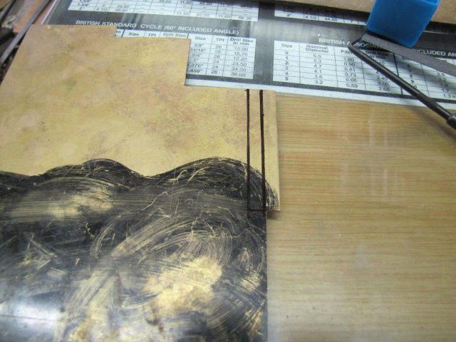
Just bandsawed the strips out. I wanted to stick the strips together like I did for the plate work on the Fred build, but I forgot that I was out of superglue... So, next best, I cleaned one face of each plate thoroughly with scotch-brite. Then on to a fire brick with a piece of thin electronics solder:
Other piece on top, with a bit of weight added to the top. Then used the butane torch to heat everything using a gentle heat; the weight pushed the two plates together when the solder melted:
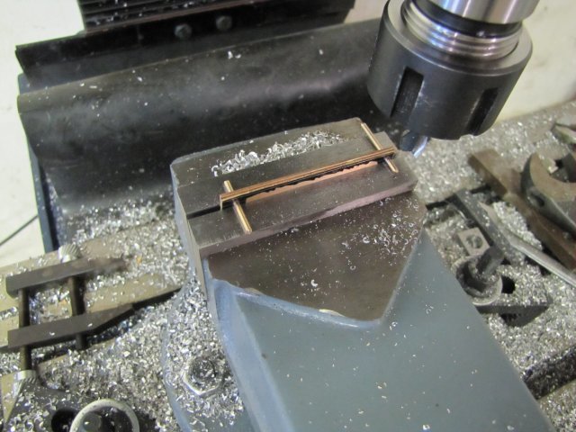
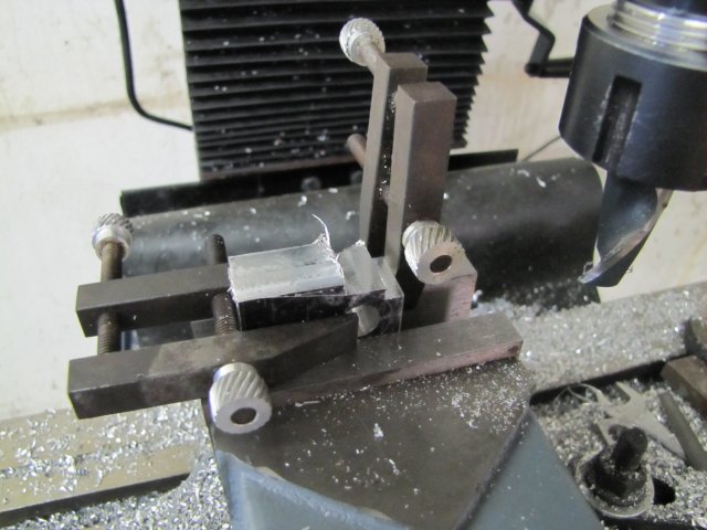
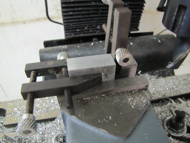
After joining the bits of plate, I marked out and drilled the holes in the end in the drill press, then pushed pins into each hole and off to the mill to get the sides down to size. The pins locate on the top of the vise jaws to keep things parallel (Thanks to John Bogs for that tip!):
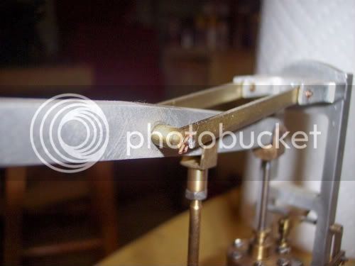
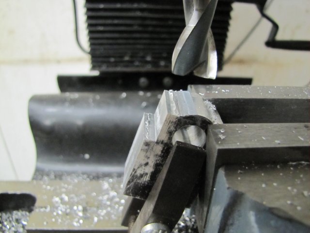
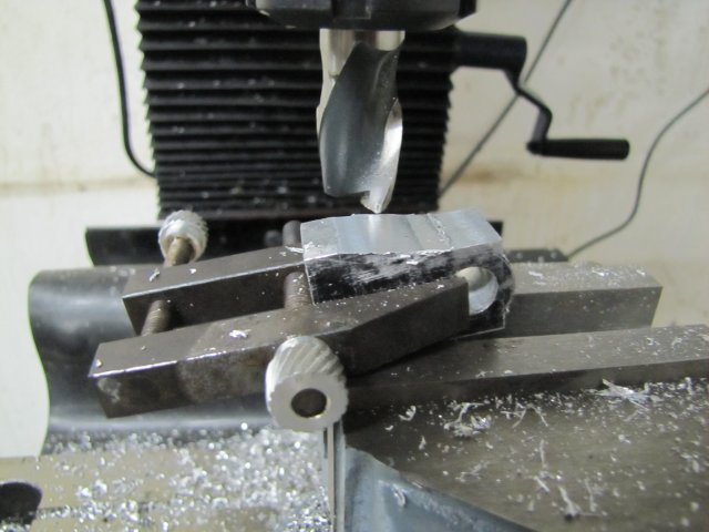
Made up another filing button; this time I actually had to turn down a bit of steel for it, but quick job nonetheless:
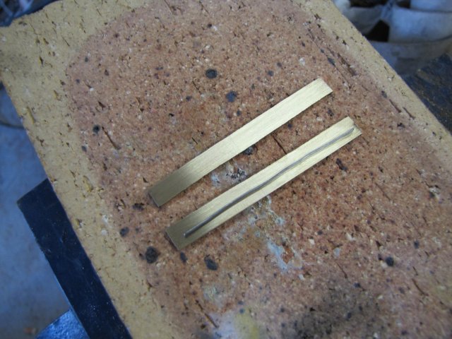
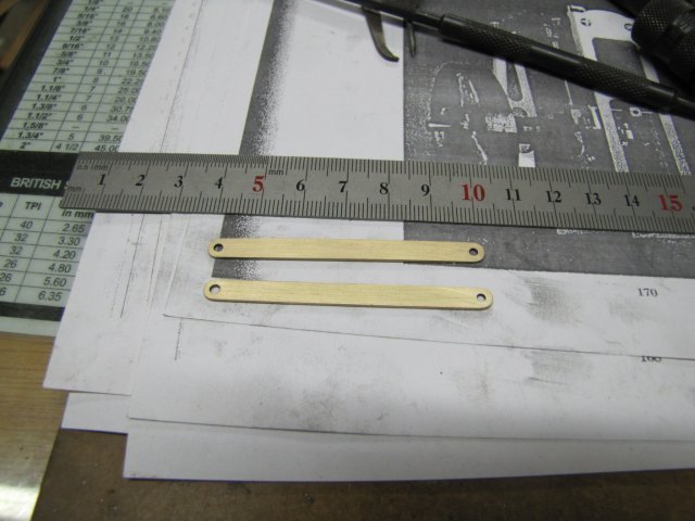
Both ends filed to shape - 5 minutes of work:
Then back to the fire brick and heated the assembly till the solder melted, pushed the bits apart with a bit of wire, and used some paper towel to wipe off as much of the excess solder as possible while it was still molten:
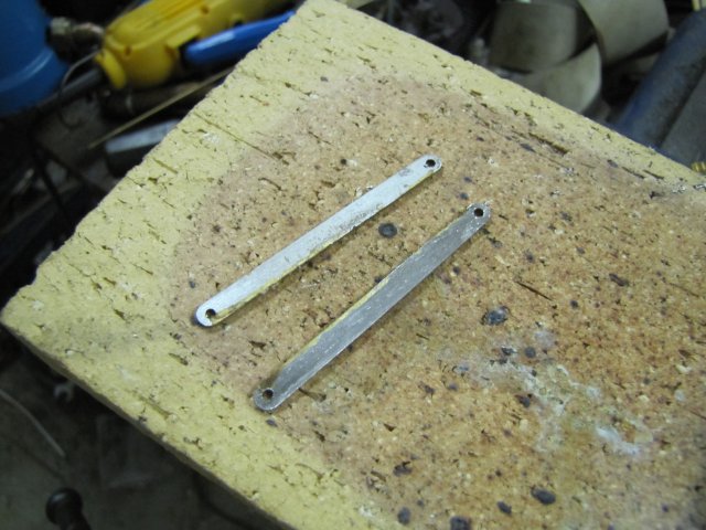
Cleaning off the rest of the solder was a bit of work; first a file, then some 320 grit sand paper, and finally scotchbrite again, but the plates cleaned up nicely:
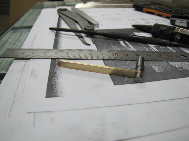
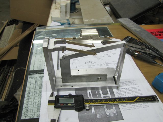
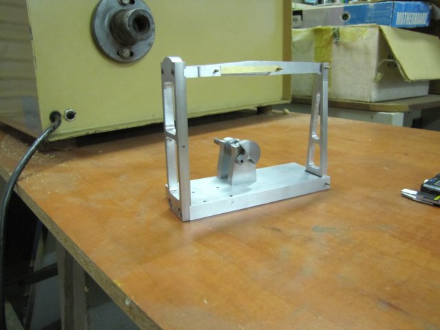
And an assembly shot; beam supported by a small square:
Regards, Arnold
And one on Zee for being a VERY good sport :bow: ;D
Chris, thank you ;D, and I'm glad you like the method. No credit to me though; the filing buttons are actually an old and established method to do round-overs (I'm certain Dean will vouch for that!) - and very effective on one-off jobs. I can nearly promise you it's quicker to do than setting up a rotary table, and not much more effort either.
:big: - thanks Carl - sometimes I need a staunch critic to remind me of things I forget. Might as well have some fun while trying to get up to standard - even if it is somewhat at the expense of said critic
. No W&W's, M&M's or Minstrels here though... Would a Smartie do ? - I could steel one from Shrek the parrot's supply; he's only allowed one a week, so a small box lasts a long time - as long as he doesn't see me me stealing it....Rick, thank you ;D, and I'm glad you're enjoying it. Did you do the wire-through-the-pins thing like Elmer suggests ? - I'm still a bit daunted by having to drill those tiny cross-holes in thin pins; I will have to make up a drilling jig for that...
Thank you Dean ;D - I've used the buttons before; just never posted photos showing them in use though. Oh yes, they are the cat's meow, the mutt's nuts - and even better than sliced bread ;D. Poor Zee
. I don't know those "Minstrels"; do they make tan ones ? - then I could -just maybe- sympathize :big:Thanks Joe ;D - What? - teasing a man who wears his tutu with pride ? - no ways I was teasing; I was obliged to do it !!!
Ariz, thank you very much ;D - and looking back to less than a year ago, yes, my skills appear to have improved slightly. But it's not easy yet; it still takes a lot of effort to do things; that's where the fun lies though
Not much shop time tonight; I was interrupted by a phone call from a friend who was helping his son with some science homework and having problems with Ohm's law - A new experience though; one of the more difficult things I had to do in my life :
; try and get a basic electronics circuit described to you over the phone to make a drawing on your own side....Back to work:
Some brass plate laid out for 2 strips to make the links from:
Just bandsawed the strips out. I wanted to stick the strips together like I did for the plate work on the Fred build, but I forgot that I was out of superglue... So, next best, I cleaned one face of each plate thoroughly with scotch-brite. Then on to a fire brick with a piece of thin electronics solder:
Other piece on top, with a bit of weight added to the top. Then used the butane torch to heat everything using a gentle heat; the weight pushed the two plates together when the solder melted:
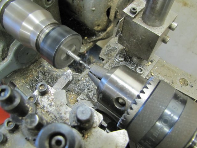
After joining the bits of plate, I marked out and drilled the holes in the end in the drill press, then pushed pins into each hole and off to the mill to get the sides down to size. The pins locate on the top of the vise jaws to keep things parallel (Thanks to John Bogs for that tip!):
Made up another filing button; this time I actually had to turn down a bit of steel for it, but quick job nonetheless:
Both ends filed to shape - 5 minutes of work:
Then back to the fire brick and heated the assembly till the solder melted, pushed the bits apart with a bit of wire, and used some paper towel to wipe off as much of the excess solder as possible while it was still molten:
Cleaning off the rest of the solder was a bit of work; first a file, then some 320 grit sand paper, and finally scotchbrite again, but the plates cleaned up nicely:
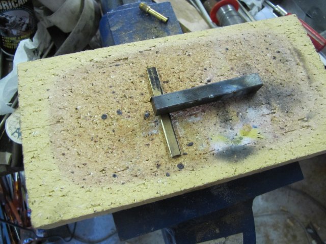
And an assembly shot; beam supported by a small square:
Regards, Arnold
And one on Zee for being a VERY good sport :bow: ;D
zeeprogrammer
Well-Known Member
- Joined
- Mar 14, 2009
- Messages
- 3,362
- Reaction score
- 13
Don't mean to hijack your thread Arnold...but I'm gonna...
Minstrels are like a super-sized black M&M but are made with the 'European' style/taste of chocolate. Americans tend towards a more bitter taste...Europeans tend towards rich and creamy. I get my Minstrels in the UK...after much pleading and begging of anyone who goes over for a visit. Having spent my 'wonder years' in Europe...my chocolate taste is rich and creamy.
Oh and Dean...the same company makes both. ;D (However, there are some Nestle products that are to die for.)
Back to you Arnold...that's going to be a great looking engine. I'm very much enjoying your thread.
zeeprogrammer said:Don't mean to hijack your thread Arnold...but I'm gonna...
Minstrels are like a super-sized black M&M but are made with the 'European' style/taste of chocolate. Americans tend towards a more bitter taste...Europeans tend towards rich and creamy. I get my Minstrels in the UK...after much pleading and begging of anyone who goes over for a visit. Having spent my 'wonder years' in Europe...my chocolate taste is rich and creamy.
Oh and Dean...the same company makes both. ;D (However, there are some Nestle products that are to die for.)
Zee,
You can order Minstrels online;
http://www.britsuperstore.com/acatalog/Minstrels_Chocolates.html
SAM
rake60
Well-Known Member
- Joined
- Jul 8, 2007
- Messages
- 4,756
- Reaction score
- 124
I did drill for the wires.
No drill jig, just a light "kiss" with a small center drill on the high spot
of the 3/32" pins. The #60 drill bit is .040" and the pins are almost
.094". There is lots of room there.
I also made a couple of those pins more than once.
Rick
No drill jig, just a light "kiss" with a small center drill on the high spot
of the 3/32" pins. The #60 drill bit is .040" and the pins are almost
.094". There is lots of room there.
I also made a couple of those pins more than once.
Rick
- Joined
- Aug 8, 2009
- Messages
- 930
- Reaction score
- 12
Sometimes as I'm scanning through thread topics I realize there's one or two that I haven't clicked on yet. Once I finally do it's like: "Hey, this is a really good build thread, why didn't I click on this before?"
This is one of those threads. Nice job Arnold.
"Grasshopper, does not the pebble when it falls into the water, make waves?" Sorry....you had to be a Kung Fu fan....
-Trout
This is one of those threads. Nice job Arnold.
"Grasshopper, does not the pebble when it falls into the water, make waves?" Sorry....you had to be a Kung Fu fan....
-Trout
arnoldb
Well-Known Member
- Joined
- Apr 8, 2009
- Messages
- 1,792
- Reaction score
- 12
;D - Thanks Carl - you're welcome to hijack a bit - I'm more into the bitter (high cacao) chocolates; a bit of 80% after dinner is heaven - especially combined with a small glass if Kirsch!
George, thank you ! - I'm in awe of the exceptional work you do; getting positive feedback on my efforts from yourself is very much appreciated indeed.
Thank you for the feedback and example Rick ;D (Great example by the way :bow I made my bushing holes a tiny bit smaller to suit available material for the pins, but I bought a bunch of small drills today to use. I also expect to re-make a couple, and break some drills in the process :big:
Trout, thanks - I'm not a big Kung Fu fan myself, but I can catch the drift... I am just building an engine to the best of my abilities, and learning in the process I have no intention of making waves; a ripple on the surface would do
Now for an update... A bit late but here it comes:
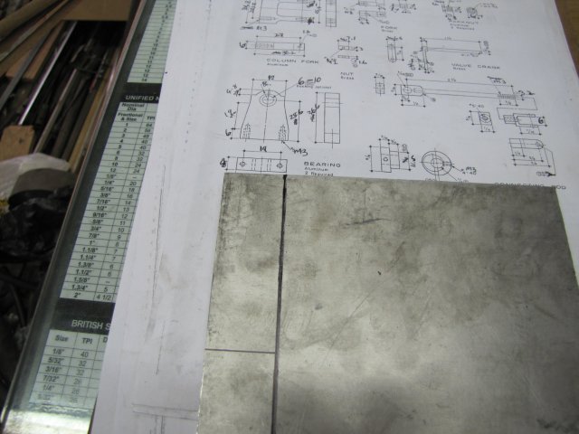
Thursday evening I started on the bearing blocks. Some 8mm aluminium plate marked out to bandsaw the material for the bearing blocks out of:
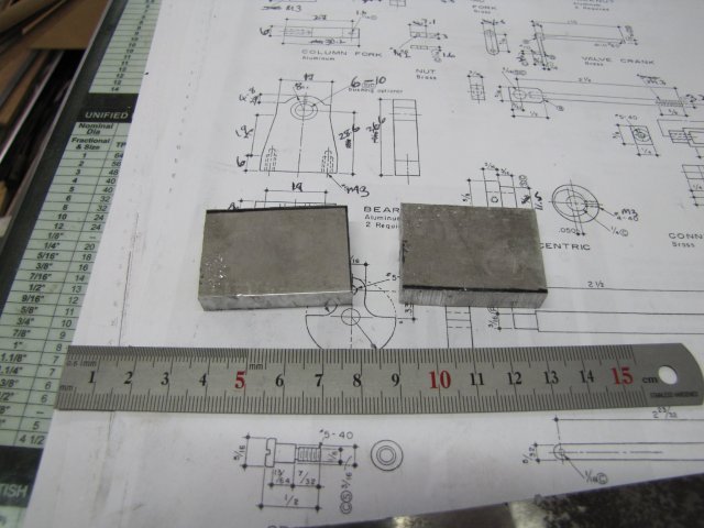
Two blocks done to start with:
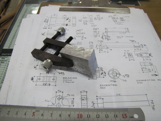
I want the two bearing blocks as near identical as possible, so I clamped them together with a toolmaker's clamp:
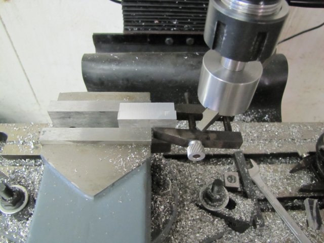
Off to the mill, and fly-cut both sides:
As there was quite a bit of excess material to remove, and I have not yet trammed my mill - which is out quite a bit, I took the opportunity to "visually" tram it in a bit better. Initially, the flycutter only cut on one side of the workpiece while passing over the blocks, so I stopped the mill after each pass, and rotated the head just a fraction so that the bottom of the spindle moved toward the side where the flycutter was cutting. Eventually, it ended up cutting most of the material facing the direction of feed, and leaving tiny scratches on the other side. Tramming near-enough for now.
Next, I squared up the bottom:
I didn't bother to clean up the top, as that will be machined to cosmetic lines; I just needed the bottom squared for marking out.
Finished off Thursday evening by doing the layout for the blocks. Not much done, but then again, I was interrupted for a period to explain Ohm's Law to a friend, so he could explain to his son for school... :
Friday evening.....
Off to the drill press, and drilled the mounting holes on the bottom of the blocks 2.5mm to thread M3. Before I started drilling, I set the drill press depth stop so the holes only goes 8mm deep:
Then I clamped both blocks together again; just using "finger feeling" to align the bottoms and the sides. This may seem crude, but the human finger is very sensitive to "height differences" between two objects, so as long as all the aligned sides feel smooth, they are pretty close in my book. Next up, center drill for the bearing (in my case the bearing bush; I decided to go with brass bushes for bearings):
Then a "Whoops - a - daisy" moment - I haven't tested how accurately my mill will move up and down on Z. The head was too low to fit the drill in:
I could test the mill's Z dovetail... Or I could just fit the 10mm collet to the nut, and insert the drill - outside of the machine:
And then fit it on the spindle - loads of side clearance available to angle it in and lock:
And a to all the experienced machinists out there who are now howling in laughter at this idiot doing the obvious... It wasn't initially that obvious, and I am sure I'm not the first to encounter this minor problem. Just maybe it helps somebody other than myself look less of an idiot!
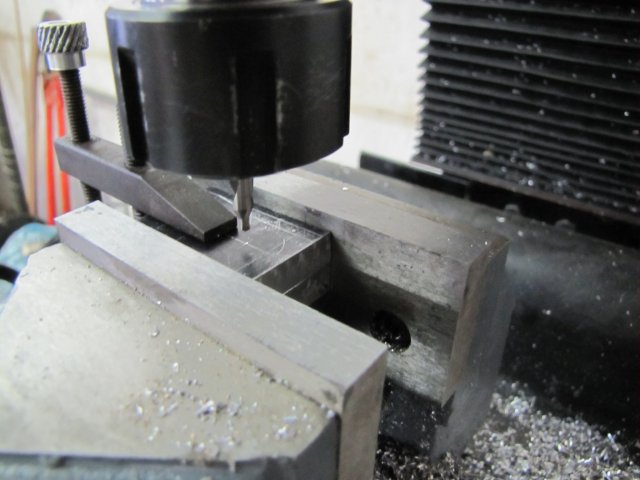
Back to work... Drilling for the bearing bush with lots of swarf flying around. Actually more than I usually allow; taking action photos could be dangerous!:
Done drilling the hole. As I wanted to press-fit bushes into the hole, I removed the drill slowly - at about the same rate of feeding it in initially - to leave a smoother finish without the need to use a reamer:
Next up, profiling the blocks. After I put the blocks in initially on an "impromptu parallel" and clamped it in the mill vise, I removed the toolmaker's clamp, and re-clamped it so that it was lying flat with the mill vise jaws. First, I just milled to the line; I just eyeballed it on the approach, but took note of the X readings on the mill dials for the Z steps:
With one side done, I once again used another toolmaker's clamp as a vise-stop:
I then flipped the bearing blocks vertically - after I de-burred them with a file while out of the vise. The clamp retaining the blocks was used to just set them horizontal in the jaws of the mill vise, and the end up against the other clamp meant I could use my prior X-readings to machine this side as well. Keeping track of Z readings would be useless though, as the "horizontal" clamp was not on center.
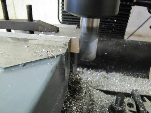
I then milled the rest off according to the X-settings I noted down earlier, and with Z feed to the scribed lines; this was more difficult than expected, as all the lines were now at the back of the mill! Next up, some light milling to contour the "decorative" tops of the bearing blocks to save on filing - "light milling", because I didn't have a lot of the workpiece clamped:
Next up, the sides of the blocks; once again, light milling, by eye to the scribed lines:
End of work for Friday evening - lots of finishing still needed:
Saturday's work follows...
Regards, Arnold
- I'm more into the bitter (high cacao) chocolates; a bit of 80% after dinner is heaven - especially combined with a small glass if Kirsch!George, thank you !
- I'm in awe of the exceptional work you do; getting positive feedback on my efforts from yourself is very much appreciated indeed.Thank you for the feedback and example Rick ;D (Great example by the way :bow
I made my bushing holes a tiny bit smaller to suit available material for the pins, but I bought a bunch of small drills today to use. I also expect to re-make a couple, and break some drills in the process :big:Trout, thanks
- I'm not a big Kung Fu fan myself, but I can catch the drift... I am just building an engine to the best of my abilities, and learning in the process I have no intention of making waves; a ripple on the surface would do Now for an update... A bit late but here it comes:
Thursday evening I started on the bearing blocks. Some 8mm aluminium plate marked out to bandsaw the material for the bearing blocks out of:
Two blocks done to start with:
I want the two bearing blocks as near identical as possible, so I clamped them together with a toolmaker's clamp:
Off to the mill, and fly-cut both sides:
As there was quite a bit of excess material to remove, and I have not yet trammed my mill - which is out quite a bit, I took the opportunity to "visually" tram it in a bit better. Initially, the flycutter only cut on one side of the workpiece while passing over the blocks, so I stopped the mill after each pass, and rotated the head just a fraction so that the bottom of the spindle moved toward the side where the flycutter was cutting. Eventually, it ended up cutting most of the material facing the direction of feed, and leaving tiny scratches on the other side. Tramming near-enough for now.
Next, I squared up the bottom:
I didn't bother to clean up the top, as that will be machined to cosmetic lines; I just needed the bottom squared for marking out.
Finished off Thursday evening by doing the layout for the blocks. Not much done, but then again, I was interrupted for a period to explain Ohm's Law to a friend, so he could explain to his son for school... :
Friday evening.....
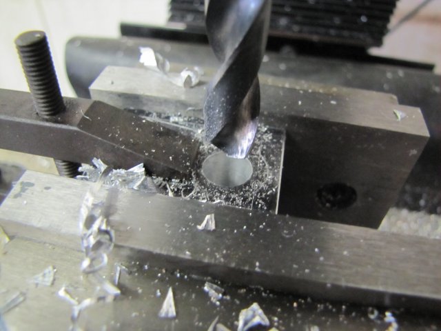
Off to the drill press, and drilled the mounting holes on the bottom of the blocks 2.5mm to thread M3. Before I started drilling, I set the drill press depth stop so the holes only goes 8mm deep:
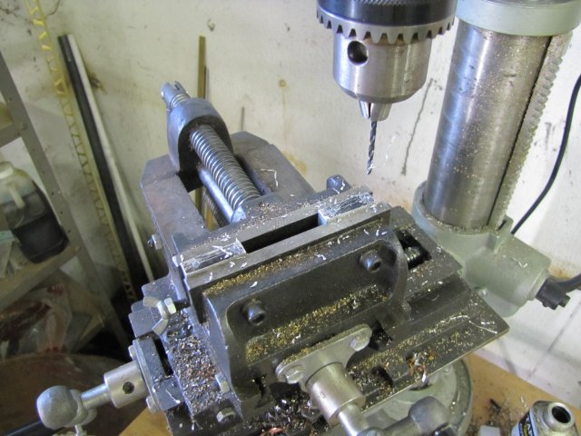
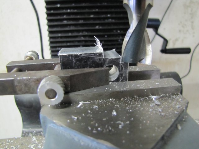
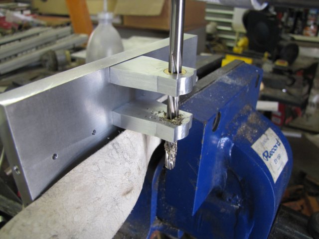
Then I clamped both blocks together again; just using "finger feeling" to align the bottoms and the sides. This may seem crude, but the human finger is very sensitive to "height differences" between two objects, so as long as all the aligned sides feel smooth, they are pretty close in my book. Next up, center drill for the bearing (in my case the bearing bush; I decided to go with brass bushes for bearings):
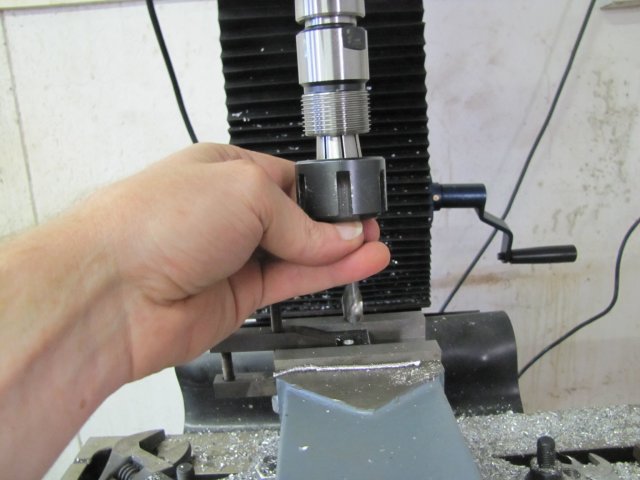
Then a "Whoops - a - daisy" moment - I haven't tested how accurately my mill will move up and down on Z. The head was too low to fit the drill in:
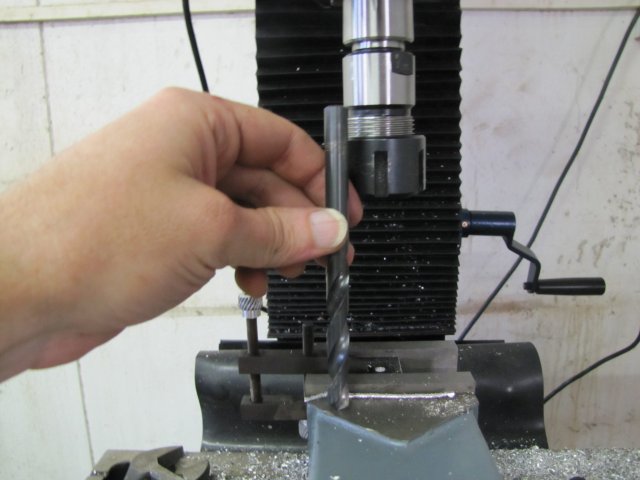
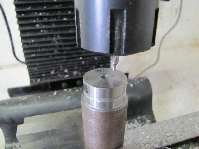
I could test the mill's Z dovetail... Or I could just fit the 10mm collet to the nut, and insert the drill - outside of the machine:
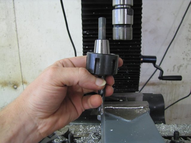
And then fit it on the spindle - loads of side clearance available to angle it in and lock:
And a
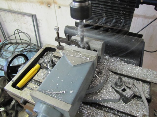
to all the experienced machinists out there who are now howling in laughter at this idiot doing the obvious... It wasn't initially that obvious, and I am sure I'm not the first to encounter this minor problem. Just maybe it helps somebody other than myself look less of an idiot!Back to work... Drilling for the bearing bush with lots of swarf flying around. Actually more than I usually allow; taking action photos could be dangerous!:
Done drilling the hole. As I wanted to press-fit bushes into the hole, I removed the drill slowly - at about the same rate of feeding it in initially - to leave a smoother finish without the need to use a reamer:
Next up, profiling the blocks. After I put the blocks in initially on an "impromptu parallel" and clamped it in the mill vise, I removed the toolmaker's clamp, and re-clamped it so that it was lying flat with the mill vise jaws. First, I just milled to the line; I just eyeballed it on the approach, but took note of the X readings on the mill dials for the Z steps:
With one side done, I once again used another toolmaker's clamp as a vise-stop:
I then flipped the bearing blocks vertically - after I de-burred them with a file while out of the vise. The clamp retaining the blocks was used to just set them horizontal in the jaws of the mill vise, and the end up against the other clamp meant I could use my prior X-readings to machine this side as well. Keeping track of Z readings would be useless though, as the "horizontal" clamp was not on center.
I then milled the rest off according to the X-settings I noted down earlier, and with Z feed to the scribed lines; this was more difficult than expected, as all the lines were now at the back of the mill! Next up, some light milling to contour the "decorative" tops of the bearing blocks to save on filing - "light milling", because I didn't have a lot of the workpiece clamped:
Next up, the sides of the blocks; once again, light milling, by eye to the scribed lines:
End of work for Friday evening - lots of finishing still needed:
Saturday's work follows...
Regards, Arnold
zeeprogrammer
Well-Known Member
- Joined
- Mar 14, 2009
- Messages
- 3,362
- Reaction score
- 13
Another great post Arnold.
I really appreciate the pics and detail. It helps me realize that what I'm doing isn't unusual or unexpected.
I really appreciate the pics and detail. It helps me realize that what I'm doing isn't unusual or unexpected.
arnoldb
Well-Known Member
- Joined
- Apr 8, 2009
- Messages
- 1,792
- Reaction score
- 12
Carl, Ernie, Dennis & Dean, thank you for following along ;D
I actually had every good intention to post yesterday's work yesterday evening as well, but was bushed, so I rather went to bed.
So I'll post yesterday's work while waking up and having my morning coffee
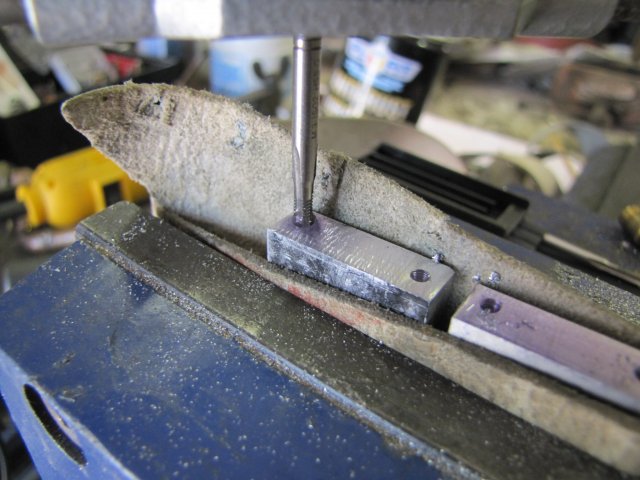
Saturday's work started by tapping the mounting holes on the bearing blocks.I'm not intimidated by those huge M3 threads anymore, so no tapping guides or anything; just clamp the blocks in the big vise with a leather strip to prevent jaw marks, a squirt of methylated spirits & hand tap the holes - carefully running through the progressive taps in the set and cleaning the tap carefully after doing each hole:
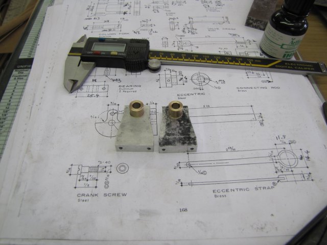
Then I turned some bushes from brass and drilled the center holes 5.9mm to ream to 6mm later. No finesse with measuring equipment to get the OD to the right size for a press fit in the bearing blocks; just turned until a test with a bearing block showed the bush _just_ want to enter but won't:
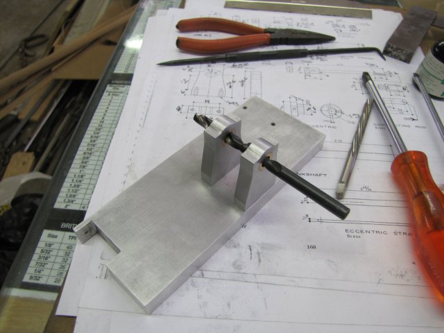
Then I pressed the bushes into the blocks with the mill vise, and mounted the bearing blocks on the base. I didn't bother to use any method of alignment while doing this, but surprise-surprise; after I turned the base around (mounting screws are from the bottom) and put the 5.9mm drill in to check alignment, it slipped right in:
Next up, off to the big vise; again with leather to clamp the base on it's side, and hand reamed the bushes to their final 6mm ID:
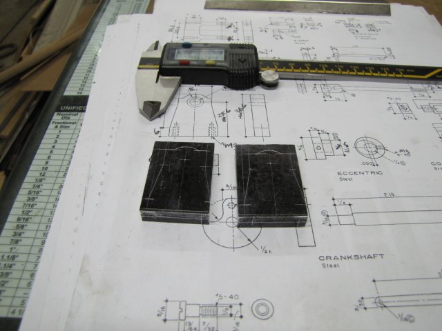
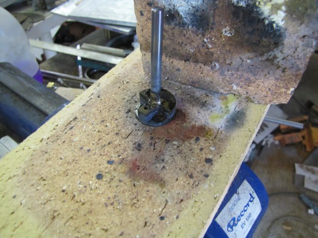
The shaft for the crankshaft was next out of some 6mm silver steel; fortunately my collet chuck on the lathe is spot-on with it's 6mm collet, so no need to use the 4-jaw to set up and center things for the bit that needed turning down for the web; just chuck the steel and turn it. Some HRS for the crank web - light facing on the front to true it up, then found center with a light touch from a small center drill and then marked out for the crank pin (crank screw on this engine):

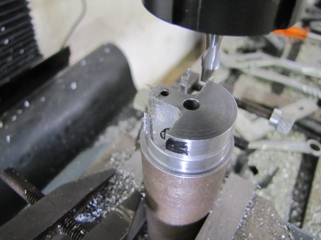
Then I finished drilling the center for tailstock support, and turned a section down to 25mm for the web OD. I also marked the web thickness with the parting tool. Then out of the lathe & off to the drill press to drill the 2.5mm hole for the crank screw. I really need to get a chuck that can take small drills for the mill... On to the mill, and used a square to make sure the piece was nice and vertical (like I did in the drill press as well!). I used a center drill clamped in the chuck to get the center of the piece (if the center drill can enter the hole part way and touch on all sides things are centered well enough for this job...) Then zeroed the dials on both X and Y - keeping backlash and feed directions in mind. Then it was just feeding in the required amounts to get the "radius" holes for the webs:
Nearly done ;D :
Then off to the bandsaw to cut off the web from the stock. I didn't even consider parting this lot off in the lathe; this HRS is horrible stuff to machine, and trying to part it off is a battle I usually end up losing. The blade I currently have in the saw insists on not cutting square, so I left a good amount of stock on the web to clean up. The plans call for a press fit, but as I had a lot of machining left on the piece, it was time to break out the torch and silver solder:
Job done - and into the pickle next:
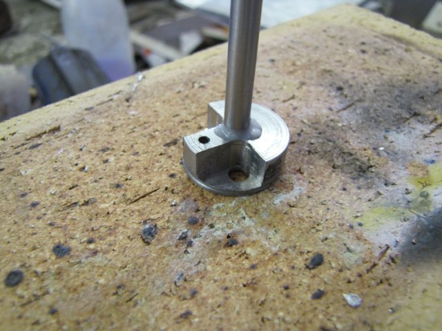
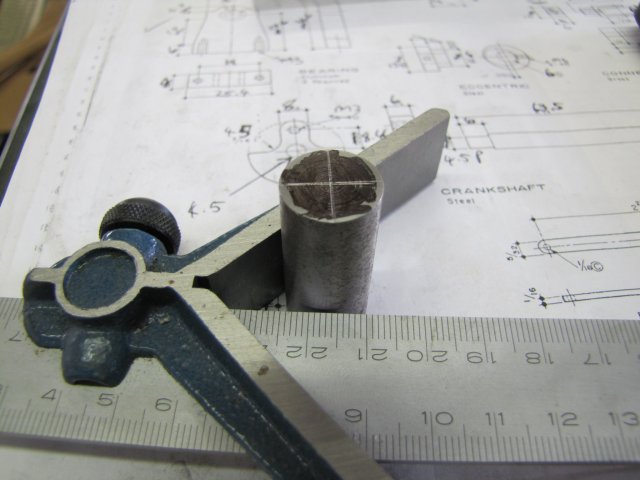
While the crank was getting a pickle, I started on the eccentric. A bit of 16mm silver steel with the center found. The V-square I have is not all that accurate, so I always scribe 4 lines; 2 approximately 90 degrees apart, and then 2 each 180 degrees apart from the first ones. That leaves a tiny little square in the center of the piece; the center punch goes in the middle of that square:
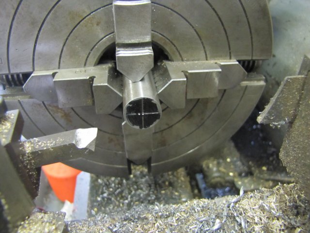
Off to the lathe, and the piece centered on the eccentric offset mark in the 4-jaw:
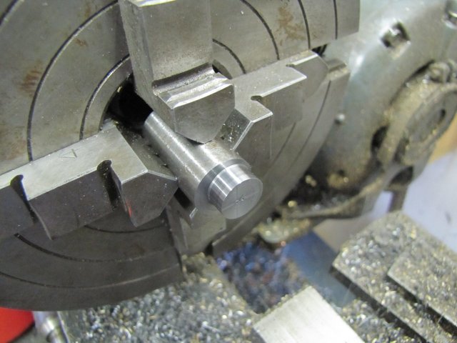
Eccentric turned with a good finish:
Then the piece was centered on the main center again in the 4 jaw, but sticking out a bit further to finish the rest and drill & ream the center hole, and parted off to length. Then off to the drill press to drill & thread for an M3 grub screw; it was nice to tap steel for a change; much better feel than aluminium. I also finished machining the crank; turned down the excess material at the end, cleaned it up to get rid of the discolouration from the soldering, and filed the rounding on the crank pin part.
Apologies for a lack of photos during the previous lot; camera batteries went flat, and when I tried the backup set, they were flat as well :-[.
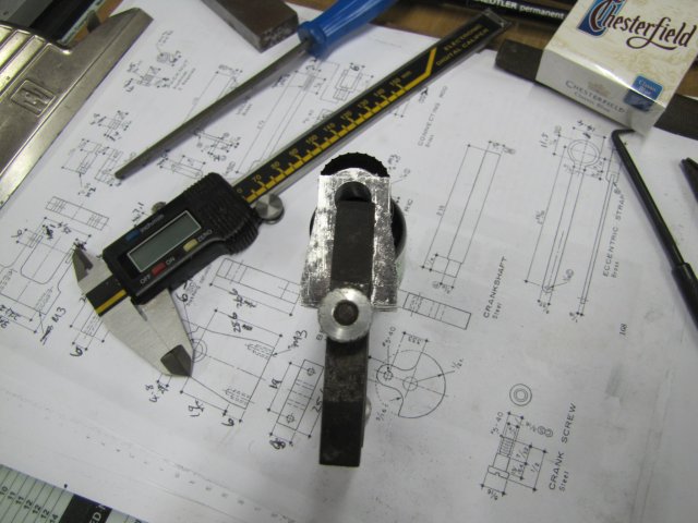
With recharged camera batteries, at least I could get a shot of the day's work trial-assembled:
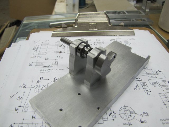
And everything together ; Whoops; forgot scale - but at least it's slowly starting to look like something:
Now, off to the shop ;D
Regards, Arnold
I actually had every good intention to post yesterday's work yesterday evening as well, but was bushed, so I rather went to bed.
So I'll post yesterday's work while waking up and having my morning coffee
Saturday's work started by tapping the mounting holes on the bearing blocks.I'm not intimidated by those huge M3 threads anymore, so no tapping guides or anything; just clamp the blocks in the big vise with a leather strip to prevent jaw marks, a squirt of methylated spirits & hand tap the holes - carefully running through the progressive taps in the set and cleaning the tap carefully after doing each hole:
Then I turned some bushes from brass and drilled the center holes 5.9mm to ream to 6mm later. No finesse with measuring equipment to get the OD to the right size for a press fit in the bearing blocks; just turned until a test with a bearing block showed the bush _just_ want to enter but won't:
Then I pressed the bushes into the blocks with the mill vise, and mounted the bearing blocks on the base. I didn't bother to use any method of alignment while doing this, but surprise-surprise; after I turned the base around (mounting screws are from the bottom) and put the 5.9mm drill in to check alignment, it slipped right in:
Next up, off to the big vise; again with leather to clamp the base on it's side, and hand reamed the bushes to their final 6mm ID:
The shaft for the crankshaft was next out of some 6mm silver steel; fortunately my collet chuck on the lathe is spot-on with it's 6mm collet, so no need to use the 4-jaw to set up and center things for the bit that needed turning down for the web; just chuck the steel and turn it. Some HRS for the crank web - light facing on the front to true it up, then found center with a light touch from a small center drill and then marked out for the crank pin (crank screw on this engine):
Then I finished drilling the center for tailstock support, and turned a section down to 25mm for the web OD. I also marked the web thickness with the parting tool. Then out of the lathe & off to the drill press to drill the 2.5mm hole for the crank screw. I really need to get a chuck that can take small drills for the mill... On to the mill, and used a square to make sure the piece was nice and vertical (like I did in the drill press as well!). I used a center drill clamped in the chuck to get the center of the piece (if the center drill can enter the hole part way and touch on all sides things are centered well enough for this job...) Then zeroed the dials on both X and Y - keeping backlash and feed directions in mind. Then it was just feeding in the required amounts to get the "radius" holes for the webs:
Nearly done ;D :
Then off to the bandsaw to cut off the web from the stock. I didn't even consider parting this lot off in the lathe; this HRS is horrible stuff to machine, and trying to part it off is a battle I usually end up losing. The blade I currently have in the saw insists on not cutting square, so I left a good amount of stock on the web to clean up. The plans call for a press fit, but as I had a lot of machining left on the piece, it was time to break out the torch and silver solder:
Job done - and into the pickle next:
While the crank was getting a pickle, I started on the eccentric. A bit of 16mm silver steel with the center found. The V-square I have is not all that accurate, so I always scribe 4 lines; 2 approximately 90 degrees apart, and then 2 each 180 degrees apart from the first ones. That leaves a tiny little square in the center of the piece; the center punch goes in the middle of that square:
Off to the lathe, and the piece centered on the eccentric offset mark in the 4-jaw:
Eccentric turned with a good finish:
Then the piece was centered on the main center again in the 4 jaw, but sticking out a bit further to finish the rest and drill & ream the center hole, and parted off to length. Then off to the drill press to drill & thread for an M3 grub screw; it was nice to tap steel for a change; much better feel than aluminium. I also finished machining the crank; turned down the excess material at the end, cleaned it up to get rid of the discolouration from the soldering, and filed the rounding on the crank pin part.
Apologies for a lack of photos during the previous lot; camera batteries went flat, and when I tried the backup set, they were flat as well :-[.
With recharged camera batteries, at least I could get a shot of the day's work trial-assembled:
And everything together ; Whoops; forgot scale
- but at least it's slowly starting to look like something:
Now, off to the shop ;D
Regards, Arnold