Arnold's take on Elmer's Grasshopper

Home Model Engine Machinist Forum

Help Support Home Model Engine Machinist Forum:

This site may earn a commission from merchant affiliate links, including eBay, Amazon, and others.
Well, you're going along nicely, Arnold, even if you had to use the brown stuff, and make the 3.2mm goof.
"Chuck dance". I like that.
Every time you show the progress picture, it looks like... progress! Nice rounding job on the cylinder.

arnoldb said:
"Sunday Driver Perambulator Operators"

Oh, the Batty Buggy Brigade!

Dean
 
Once again...great idea with the wooden block. I would have never thought to do that.

I hope to remember that in the future.

Chris
 
Thank you Dean ;D - :big: I like "Batty Buggy Brigade"!

Chris, thank you. I'm happy that there is some useful tidbits for others to use - that makes it all worthwhile sharing the build.

Not much progress tonight; I went to the shop, sat down on a chair and tapped all the holes in the cylinder with a crude tapping handle and guide block left from my previous build.
normal_IMG_1035.JPG

I find that sitting down while tapping small holes makes things easier to keep stable. Fortunately no mishaps; - ran through all the holes with each tap in the set, cleaning the tap thoroughly after each hole.

Regards, Arnold
 
Lookin good, Arnold.

guide block left from my previous build.

That's the neat thing about this. The more engines you build, the more tools and fixtures you have.

Dennis
 
It's the little things accumulated over time that make it easier.

They say necessity is the mother of invention. I think it was laziness ;D
 
Thank you Dennis ;D - Yes, the little "tool building" on the side helps a lot! - but I'm actually a bit embarrassed at the crudity of that particular tapping guide and "handle" - It gets the job done, but I think its time to make some better looking ones ;)

Kevin, Thank you ;D I think you might be right about laziness; I'm inherently lazy so I tend to try and find easy ways... Sometimes those easy ways just needs a bit of work up-front. Sort of like writing little scripts that sends me an email if something is wrong - instead of having to check through tons of logs every day that just shows everything is right - and the wrong thing gets overlooked because of "data overload" ;)

Had a bit of a slow week in the shop thus far...
Yesterday afternoon after work, I got a couple of bits of brass plate together and just started layout on the valve chest. Further work was stopped by some out-of-town, but very welcome visitors pitching unexpectedly:
normal_IMG_1036.JPG


After a bit of a late start today (caused by mentioned visitors and perhaps too much of fine bottled Scottish produce), I cut off and milled the aluminium block for the valve chest to size, then milled out the inside. My sharp 6mm slot mill was too big for this job, and the sharp 2mm slot mill maybe a bit too small. I settled on using the only in-between size I have; a 4mm slot mill... It was a bit blunt though, so made a bit of a mess:
normal_IMG_1037.JPG


Some filing cleared up the mess though:
normal_IMG_1038.JPG


The part was then mounted and centered in the 4-jaw chuck and drilled and tapped and turned for the packing nut as per plans. When I drilled the 2mm hole that will accept the valve rod, I drilled it through, and stopped the lathe without retracting it. Then I fed the tailstock in to touch the other opposite internal side of the valve chest, and "squeezed" a bit by feeding the , retracted slightly, turned the chuck manually a bit and did the same - a couple of times. Then powered on the lathe again and with tailstock feed just "touched" the marks left to form a center hole mark for the smaller 1.5mm drill that then followed to drill into the opposite valve rod end guide.

I also sawed and milled the brass plates for the valve plate and steam chest cover to size. Once done, I kept the bit of plate with the best surface finish aside for making the valve plate. The other plate (valve chest cover) was then marked out and drilled for the mounting holes. I then physically tested that it matched the cylinder mounting holes by screwing in some 2mm screws through it into the cylinder block, and then clamped the cover plate, steam chest and valve plate together with a toolmaker's clamp, with the cover plate at the top. Then using the cover plate as a drilling template, I drilled the mounting holes in the steam chest and valve plate:
normal_IMG_1039.JPG


Next, I marked out the valve plate. Instead of using my automatic center punch, I just used the point of my scriber to "push down hard" at "X Marks the spot" for the drilling locations:
normal_IMG_1040.JPG

The holes that need to be drilled are small - 1mm, and I've found that my automatic center punch is not always accurate; it seems to "wander" a bit.

That lot then went off to the drill press to drill the 1mm holes, and then I flat-lapped the plate on some 800 grid emery paper on the glass plate that makes my surface plate:
normal_IMG_1041.JPG

The last couple of passes on the emery paper was cross-ways from the way the valve would travel on the plate, so that it can "wear" in without losing air/steam. If you are wondering why I used the drill press instead of the milling machine to drill the holes... The drill press has quite a bit of backlash between the point where the drill bit contacts the workpiece and where you actually start feeding the drill. This "in-between" backlash bit is easy to feel on the feeding handles, and I used it to my advantage here - just touched the drill down on the mark, then started the machine and drill bit does not wander too much.

Next up, I needed some M2 threaded brass rod. I don't have that!. I fell back on 2mm "bronze brazing rod" - this stuff is tough, but makes for good threaded rod, so for the first time EVER I trusted my hands to the lathe under power. I used the tail stock die holder to start the thread manually, then with the lathe in back-gear and lowest speed, started making some threaded rod:
normal_IMG_1043.JPG


I ended up with this:
normal_IMG_1044.JPG


Why did I need so much threaded rod? - because I decided on "studs 'n nuts" - though the "nuts" still need making!
normal_IMG_1045.JPG


And an overview...
normal_IMG_1046.JPG


Regards, Arnold
 
A good day's work, Arnold. Things are looking very good!
Studs and nuts; Yay. They really add a lot to the appearance of an engine.

Nice work!

Dean
 
Glad to see the post...I was starting to get 'Arnold Withdrawal'. The engine is looking great. But I'm thinking you're enjoying the mill a little too much. Can I help with that?
 
Thank you Ed ;D - but there is always room for improvement :)

Dean, thank you ;D - with a limited selection of little screws / bolts in my inventory, I'm actually "cheating" by using the studs 'n nuts; it is easier to make up and use :big:

Thanks Carl ;D - :big: - I am enjoying the mill - it helps me build booboos faster than I have in the past :big:. Shush - you be quiet and let your knee heal; then you can get cracking on your boiler build; you won't have time left to help me then :big:. "Arnold Withdrawal" - now THAT's a new one to me; usually people are only to happy for me to keep quiet or disappear. Thank you!

Today started in a most frustrating fashion in the shop. I needed some 3mm hex rod to make the nuts from, but I could not get any setup in the mill to work to make reasonable lengths. Wasted a couple of hours and a lot of brass on that. I nearly gave up, but a good "kick-my-own-butt" shot worked; I made nuts when building Fred, and had passable results...

So I ended up making the nuts the same way as then; chucked up a bit of 3.2mm brazing rod in the lathe with about 25mm sticking out, used the collet chuck nut's clamping grooves as indexing marks, and just filed flats on the rod to make up the hex. Then drill & tap, and part off little nuts, catching them in a spray-can top to prevent it going into the swarf:
normal_IMG_1048.JPG

20 minutes of work, and I had enough nuts and a couple spare. Lesson learned; for some things nothing beats a carefully applied file!

As I made the nuts, I threaded them on a bit of rod; to keep them from falling into the dark abyss below the mark-out table where the metal-eating monster lives. The rod also came in handy to deburr and finish of each nut; screw it to the tip, and file down the burrs; the rod makes a great handle.
normal_IMG_1049.JPG


One thing that did go right was a narrow parting tool. My normal parting tool is 2.5mm wide, and can waste a lot of material when parting small things. Before I even started doodling around with making nuts, I took an old blunt "bi-metal" metal cutting jigsaw blade and ground the tip into parting tool form on the bench grinder. I also made a quick and dirty holder for it to fit on a QCTP holder - I didn't know if it would work, so didn't spend too much time on the holder; just an edge milled off a block of HRS, slightly "V"'d with a triangle file at the bottom and a bit of plate to clamp down from the top. I didn't even bother to make an edge to the top plate; the saw teeth would dig in and hold... I hoped... :
normal_IMG_1050.JPG


To minimize burrs left on the parted bits, I ground the parting point at an angle instead of square:
normal_IMG_1051.JPG

After grinding the tip to shape, I carefully stoned the tip on the oilstone to get it really nice and sharp. This impromptu parting tool works a treat, so I'll definitely make a better holder for it to keep with my other toolbits!

After making the nuts, it was time to do something more "solid", so I laid out the piston rod fork:
normal_IMG_1052.JPG


Off to the mill, and some drilling, milling and slitting:
normal_IMG_1055.JPG

Not the cleanest of slitting jobs, but nothing a quick bit of filing could take care of.
And the part turned out to be a booboo... After cleaning off the "excess" left after slitting it off, I wanted to drill the 2.5mm hole for threading to screw it on the piston rod. Went to the drill set, and the 2.5mm drill's not there.... It was in the pin chuck. That I used to drill the "2mm" "Close" hole for linking the fork to the beam. Bummer. So I re-made the fork, with the correct sized holes drilled where needed.

Making the piston rod was a breeze; just some turning down on a bit of 3.2mm bronze brazing rod on each end to get it to 3mm to thread M3 as per plans. Well, not quite as per Elmer's plans; I have to make everything metric so some improvisation needed ;D And in case anybody's curious as to why I use the brazing rod so much; it's readily available here in Namibia and fairly cheap. Brass rod in this size is completely unobtainable here, so I use what I can. There is an advantage to the brazing rod though; it seems to be a lot tougher than brass, so good for things like screws and so on.

Well, I had the fork (the new one; not the "forked" fork), and the rod, so next it was the piston. A simple turning job from some brass. First faced, center drilled, drilled 2.5mm for M3 thread to sufficient depth, threaded, and then drilled 3.2 mm 3mm deep. I measured the bore on the cylinder at just over 12.2mm, so I turned some 1/2" brass rod (OK, 12.7mm brass rod!) down to 12.3mm. Put in some grooves for the oil grooves with a threading tool , and with a file a good chamfer on the outer edge, and then carefully turned down the outside further. I used the cylinder as reference; checking after each pass (the last ones were 1 thou passes - SHARP toolbit needed) till it went into the cylinder tightly. NOT so tight as to freeze up though! Some 800 grit emery wrapped around a rule did the final sizing; leaving the fit a "light push fit" with the cylinder:
normal_IMG_1056.JPG


Then I started parting off the piston from the stock. About half-way down I stopped. From my limited experience of doing pistons this way, I know that parting raises the metal on the side a bit, so I did a check with the cylinder. Yep! it did it again. With a file, I put a chamfer on the side where I was parting off, but when checking with the cylinder it was till a bit tight, so the rule with the emery took off the last bit of resistance. Then I finished off the parting cut.

For today's work, I ended up with this lot - not much, but at least some progress:
normal_IMG_1057.JPG


And an assembly shot:
normal_IMG_1058.JPG


Regards, Arnold
 
Very nice work Arnold :bow: :bow: :bow: :bow:

Another engine nearly complete ::)


Regards Rob ;D
 
Ah! The tip about parting and spreading of metal! Thanks Arnold!!!

I'm just in the process of making the pistons for my loco.
Messed up the first go...measured a difference of .02 to get near required diameter but forgot to take half of that. ;D Stopped working because it was clear my mind wasn't on it.

Your post is a help.

Very much enjoying your thread.

 
Rob, Thanks Mate ;D - it's getting there!. Now how about an engine project from you now ??? stickpoke ;D

Thank you Zee ;D ; the "half" amount of infeed has caught me many times as well :big: - Seems to be getting less, but like you say, if your mind's not on it, it will happen. I've started using days like that for sanding bits down; worst that can happen is you give yourself a manicure, instead of getting a finger in a chuck!

Today's work was a lot of itty bitty parts. I decided to make the valve rod from 2 parts instead of turning it down from one lump; too much of a waste for my piggybank to do that.

I started with the head part of the valve rod from some 6mm brass rod turned down to size, then slit the groove and milled the sides down for the flats. A quick run-trough with a 1.5mm drill followed:
normal_IMG_1059.JPG

After that, I parted the head off in the lathe, then grabbed it in a collet and drilled a 2mm hole 3mm deep into it for soldering the rest of the rod to.

The rest of the rod was easy; just turned down one end of a bit of 2mm brazing rod to 1.5mm with just enough sticking out of a collet to do this. Then moved it out further from the collet, and threaded M2 with the tailstock die holder. Removed the rod from the collet, and after calculating how long it needed to be with the additional 3mm bit that had to be soldered in the head, cut it, cleaned the cut end and with a little speck of electronics solder dropped into the hole in the head, heated the lot gently and pressed the rod into the head. Some solder appeared and formed a fillet around the top, so a pretty good joint. A bit of clean up, and the valve rod done:
normal_IMG_1060.JPG


I've been dreading making the valve. But it had to be done, so I marked it out on a bit of stock that I had already milled down to the right thickness:
normal_IMG_1061.JPG


Clamped it in the mill, and carefully worked out the readings on the dials to get the right size. Then plunged in with a 2mm end mill. The pocket must be 0.8mm deep, slightly over the "normal" depth for such a small mill, but this one is good quality and new, so sharp. I decided to do the whole depth in one pass instead of 2 shallower cuts. Worked a treat ;D:
normal_IMG_1062.JPG

I'll have to get shop air to the mill for jobs like this; I nearly went faint blowing away swarf to see what was happening.

Flipped the block around, and milled a 2mm slot through it for the valve rod, and a 1.5mm cross-slot for the nut.
Then I sawed the nut from the parent stock in the big vise with a junior hacksaw, leaving about 1.2mm excess that I then cleaned up in the mill.
I don't know why I was apprehensive about making the valve; I think it came out OK:
normal_IMG_1063.JPG


Next I turned up the fork pins:
normal_IMG_1065.JPG


Then I got busy on some sundries. I turned up the pack nuts from brass hex rod. Then made a new crank screw with a smaller head; the original just looked out of proportion. The bits of brazing rod that were keeping things assembled up to now was shortened to length, and then I cross-drilled them like Rick mentioned earlier in the build; touch with a 1mm center drill, and then drill through with a 1mm drill - the center drill is a bit too short to make the hole through. And yes, I re-made the one pin twice :-[.

The valve nut was made from some brass plate; I just marked out a strip, drilled & tapped the hole, then once again with the junior hacksaw cut it from the plate. A quick bit of filing, and it was done. I also made a thin washer from brass to put on the main shaft between the web and the bearing, as there was a tiny amount of binding there, and a little spacer to add to the valve crank.

I then tore down everything, hoping that the "Bling Fairy" would come on a visit tonight:
normal_IMG_1066.JPG


Not much left to do now; some nice brass bolts for mounting the cylinder to the base, 2 more pins need cross-drilling, a steam connector, and of course the flywheel - that will be the most work.

Regards, Arnold
 
You really moved along on this build, Arnold. You're almost done already!
Nice new bits you got done today. Every time I see you making something like the valve,
I get all happy for you with your new mill. A mill is just so great for... milling! ; )

Dean
 
Arnold,
Looking good. I really like the look of your pins...everything else, too.
Dennis
 
Hi,
Your coming along very nicely on your project! Love your innovative thinking process and a great thread. You desire some "Karma"! By the way, you might want to try using a vaccum to remove chips when milling. I do that sometimes myself on little jobs. Rather listen to a vacuum than a compressor. A vaccum in blow mode. Don't want to suck in hot chips!

Dave
 
Oh, yes. Oh, YES! That is looking great Arnold. I do like the use of studs and nuts rather than the usual bolts etc. Using brazing rod, I do it all the time as my father gave me several pieces of it when he was still working. It can be a bugger some times though, that or he gave me some sort of alloy material. I can't wait to see this one ticking away. It won't be long.

Cheers


BC1
Jim
 
Arnold I missed your last progresses... this Elmer's Grasshopper is going to be a very beautiful engine, I didn't know it was so nice and with those beams and levers it would be a pleasure to see while running

and you are doing it with a high degree of accurateness :bow:

 
Thank you Dean ;D - I love the mill; it's making a lot of things quicker and easier. But I'm also glad I went without it for so long - I learned a lot by NOT having it, and that is just as valuable ;D

Thanks Dennis ;D - I might be tempted to make cotter pins like you showed :bow:, but those holes are small!

Dave, thank you very much, and welcome to HMEM ;D. I did consider the shop vac', it's standing right next to the mill. But this one kicks up one heck of a noise; I can't hear myself think when it's running; it's a LOT louder than my compressor ;D I'll be laying air in the shop in future anyway; I could use a decent cooling system for both the lathe and the mill, and spray-mist seems the way to go ;D

Thanks very much Jim ;D - Yes, those rods are different alloys. Machining can be tough on it, but I seem to have gotten used to it :big:

Ariz, thank you ;D I don't know about my accuracy though; some issues might still arise from my quick conversions to metric; I hope I caught all those, otherwise I'll be re-making some more parts... And I hope this engine will be interesting to watch; that is one of the reasons I chose it for building.

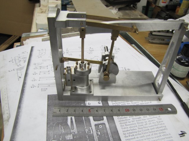
I really hoped to have this engine running by tonight, but unfortunately, time ran out with incomplete parts...

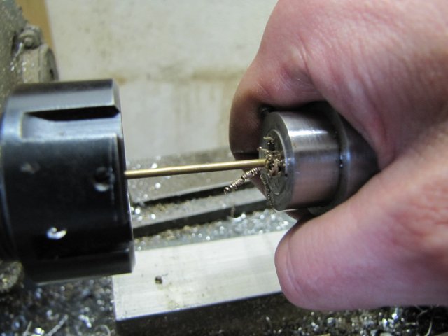
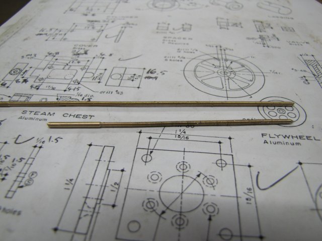
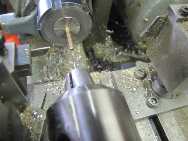
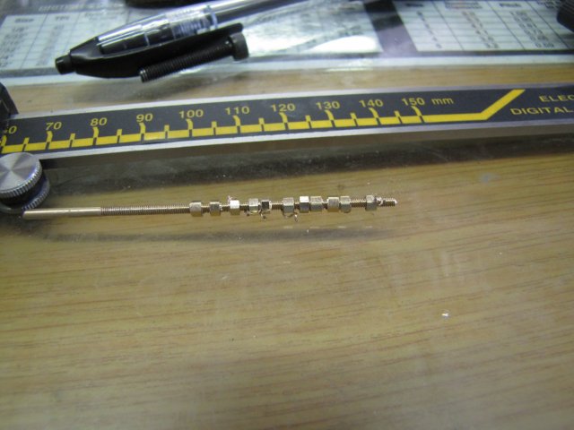
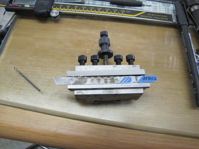
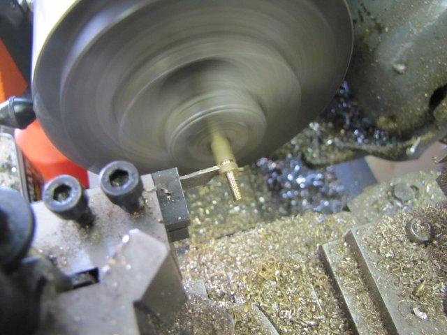
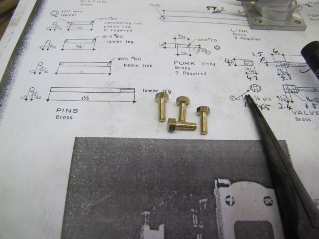
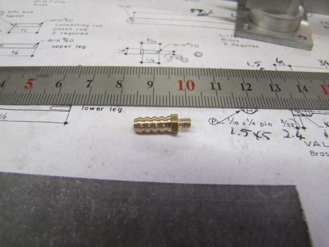
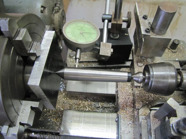
First thing this morning, I started turning the new cylinder mount bolts from some 5mm hex rod:
normal_IMG_1067.JPG


Batch finished:
normal_IMG_1068.JPG


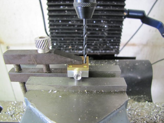
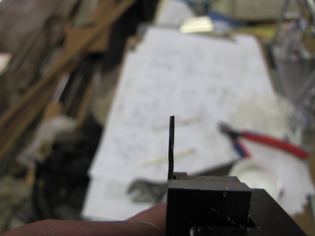
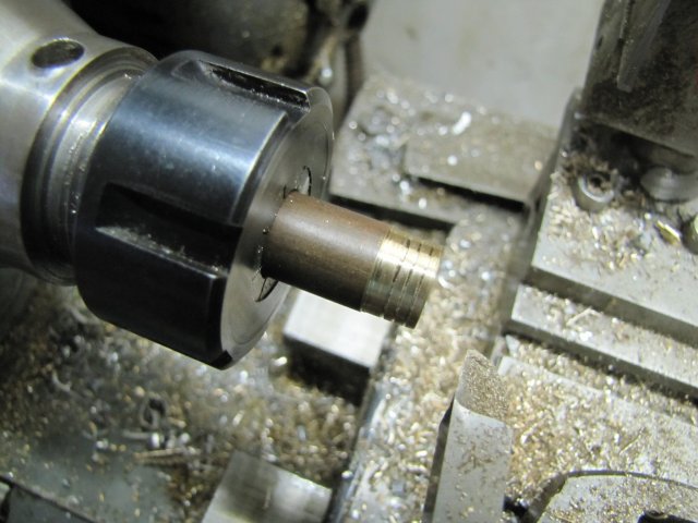
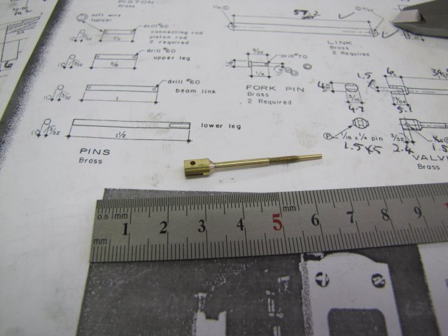
Next, the steam connector:
normal_IMG_1071.JPG


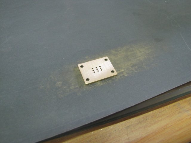
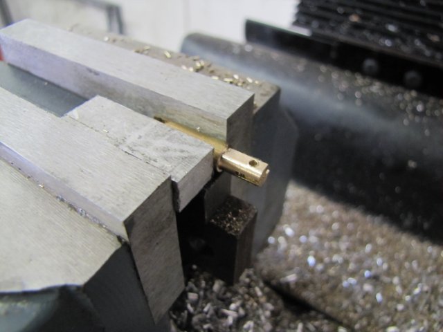
The last retaining pins were also made up and cross-drilled. Once again, one of them twice. I also forgot the pin in the valve rod head and made and fit that.

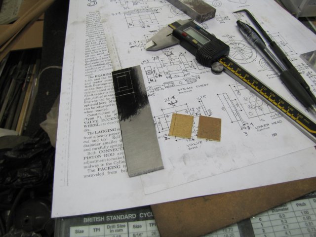
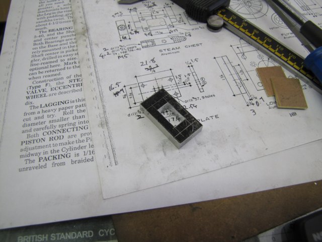
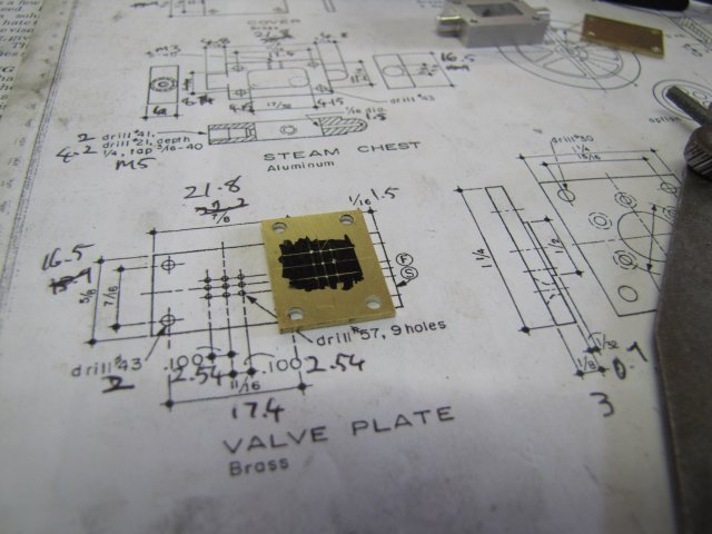
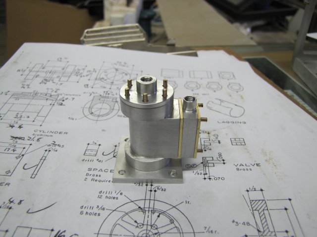
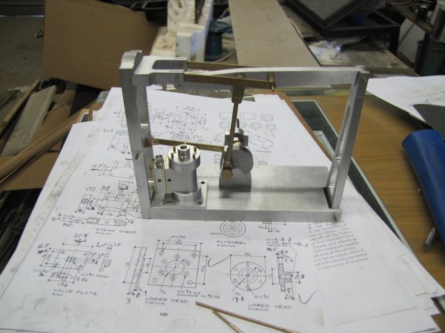
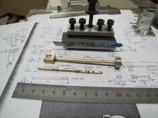
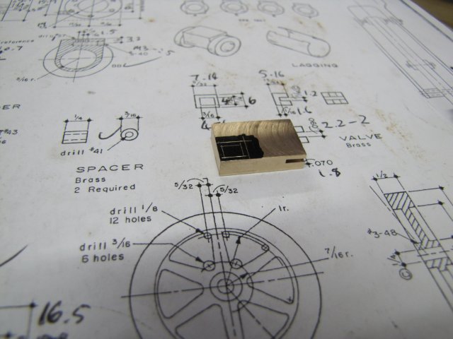
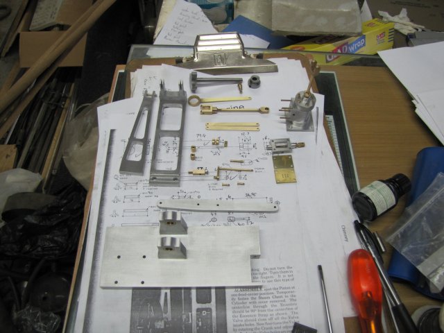
At this point I went through the entire set of plans; I'd checked of most bits as they were done, and nothing except the flywheel was outstanding. The extra bits that were not on the plans that I made like the steam connector and cylinder mounting bolts were all there. One of the items I added to the list was packing for between the different layers of the cylinder to valve/steam chest and steam chest cover assembly. I don't really know if that's needed though. So "only" the flywheel to go.

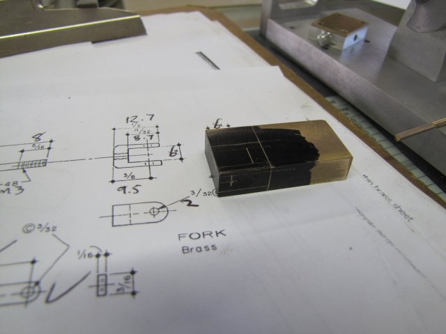
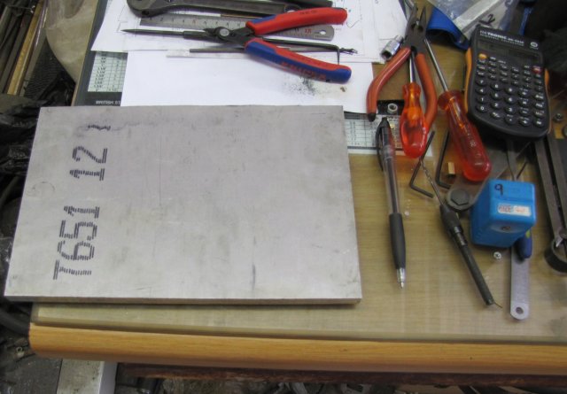
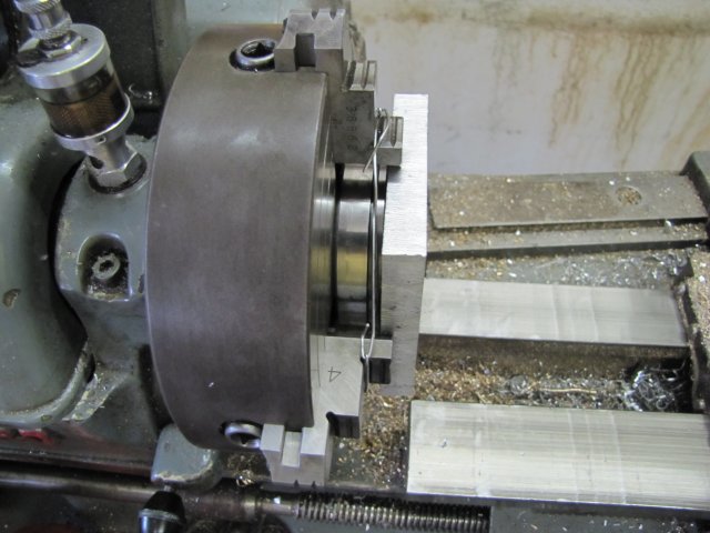
I don't have round aluminium stock of a suitable size, so the flywheel have to be made from about 1/6th of a sheet of 12mm aluminium plate I have:
normal_IMG_1072E.JPG


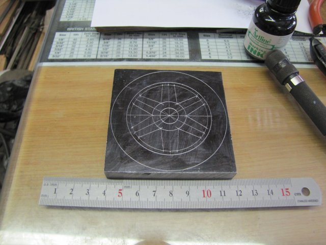
Bansdsawed off the block, and marked out for the flywheel:
normal_IMG_1074.JPG


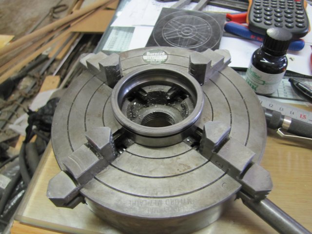
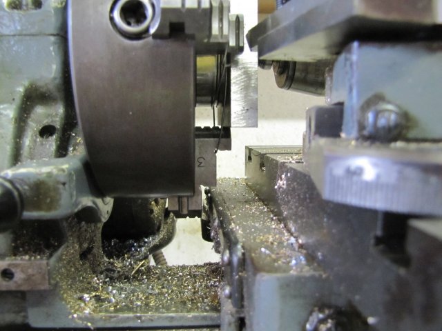
For mounting in the 4-jaw chuck, a bearing outer ring is an ideal parallel:
normal_IMG_1075.JPG


Back on the lathe, and centering ; I REALLY need to make a pump center! :
normal_IMG_1076.JPG


I tied down the "parallel" with some binding wire; only really needed from keeping it flying around while drilling the center hole; after that, tailstock pressure on the workpiece will keep it down pat. If you use wire on the lathe like the, make sure all the ends are tucked away so that they wont be flying about - they are difficult to see when the chuck is revolving.
normal_IMG_1077.JPG


A final, but very important check. Looking all over for possible places where for example the chuck jaws could clip the lathe apron and so on; On this job, there were a lot more bits protruding from the chuck than normal for me (and that does not mean that I do most of the same checks "normally" - just some extra care on this job. Most likely culprit, the extended chuck jaws running into the apron:
normal_IMG_1078.JPG


First off, a center drill into the workpiece, then put in the revolving tailstock center and applied a good bit of pressure. Then some big interrupted cuts; well big for me anyway; 30 thou infeed at a time with a sharply honed HSS toolbit and the lathe on lowest non-back-geared speed. I could have cut down a lot more of the "corners" of the workpiece on the bandsaw, but my saw does not have a proper vertical operation plate, and with the blades I have available struggles to cut this thickish aluminium well. So whether in the saw or on the lathe, this is a slow job for me:
normal_IMG_1079.JPG


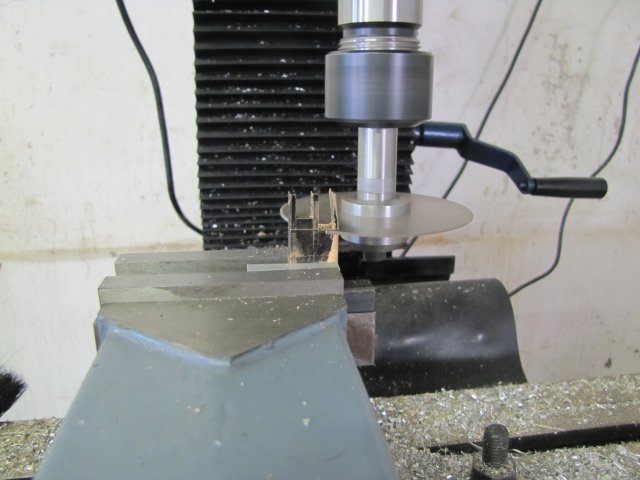
After that, I drilled and reamed the hub 6mm. With the excess parts now thinner, I bandsawed most of that off, and used Bogs's method to turn down the rest.

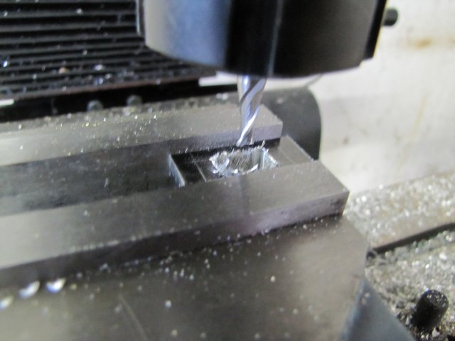
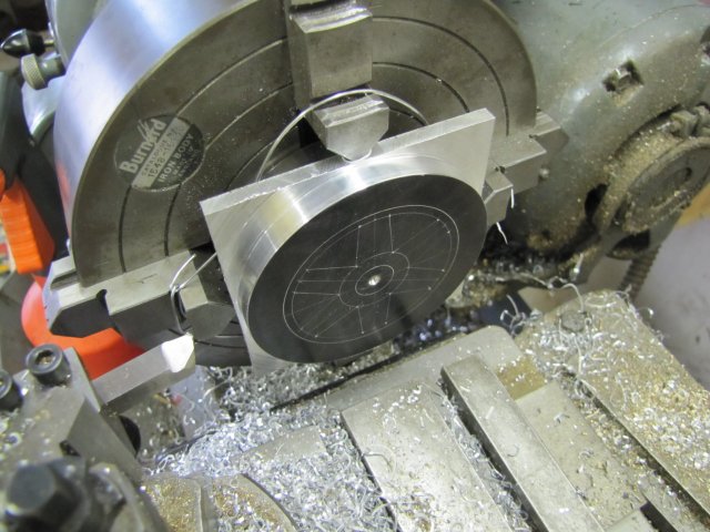
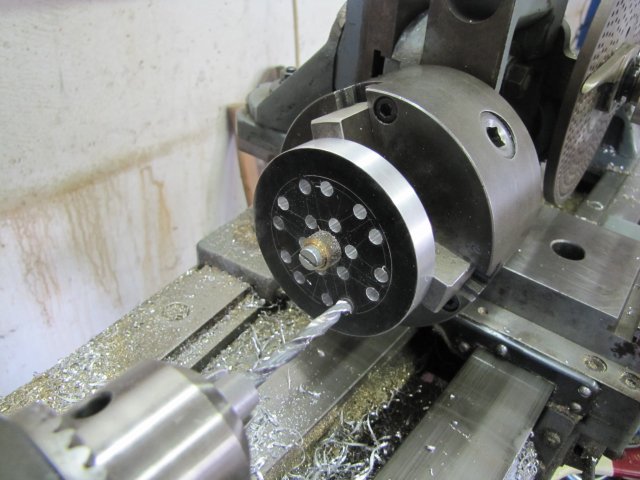
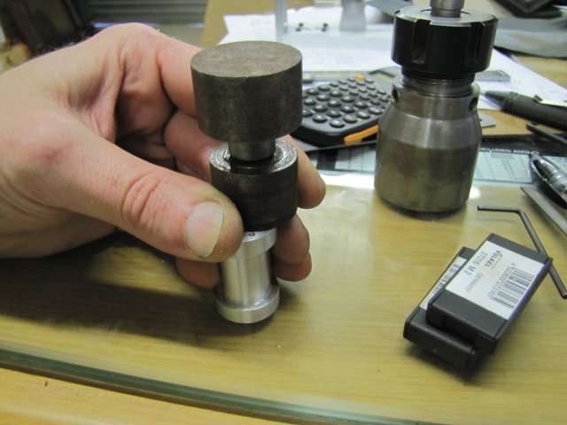
Next I needed to drill some holes in the workpiece. A check with a close-fitting 6mm drill bit and one of the 3-jaw chuck's outside jaws showed that things would work just dandy for a mandrel mounted in the chuck and pulling the workpiece flat onto the jaws, but allow enough space for drilling operations:
normal_IMG_1080.JPG


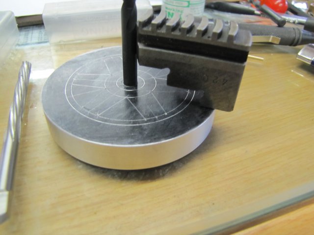
I made the mandrel by chucking some 6mm silver steel in the 3 jaw with the outside teeth mounted and the end of the rod slightly below the "depth of the jaw faces plus thickness of the workpiece". A quick drill & tap for M5 in the silver steel and a screw (preferably bolt, but I had none) and washer (crude offcut in my case) can be used to clamp the workpiece to the jaw tops. I know my 3-jaw's outside jaws are fairly concentric, so no need to actually turn the mandrel in-place, but that would be more accurate. With this lot assembled, I drilled all the holes for the corners of the spokes with the dividing head mounted on the vertical slide. Once again, I deviated from the plans a bit, and took approximations from the plans, but kept a careful eye on mirroring holes for the sides of the spokes. I just used the layout on the workpiece as an approximate reference:
normal_IMG_1081.JPG


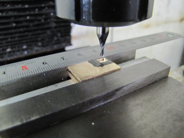
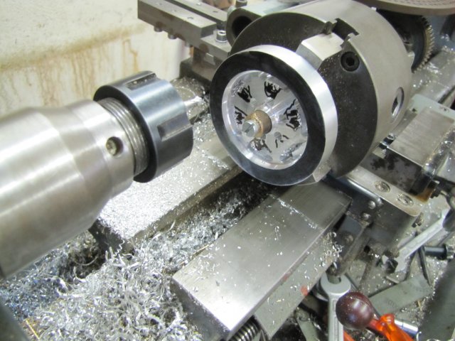
Hopefully the last time I'll be abusing my dividing head as a rotary table; milling the the roundings:
normal_IMG_1082.JPG


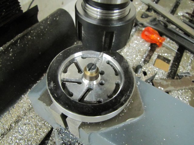
Then with the same 6mm mandrel, mounted "just too low" in the milling machine vise, I could clamp down the workpiece. Some careful checking, and I found the spots where I could loosen the workpiece touch it to the side of the lowered milling cutter cranked into the outer hole and mill a straight line into the hole next to the hub:
normal_IMG_1083.JPG


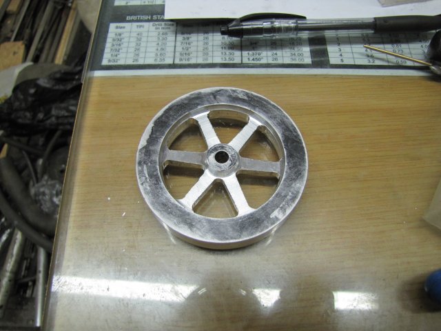
I ended with a crude flywheel tonight; lots of cleanup still needed, but after some more it should be passable.
normal_IMG_1084.JPG


I wanted to have this engine running tonight, but had to give up at this point, as I was getting tired. "Tired" and "workshop" just does not mix!
Today's work very likely is not a prime example of "How to do it" - while typing up this post I thought of some alternate and possibly better ways to do things with the tools I have available, but that experimentation will have to wait for a future date. It will most likely be a slow shop week as well, and I have "work" work booked for next weekend. I wish this weekend was a day longer!

Regards, Arnold

Darn; the "Bling Fairy" didn't even visit :big:
 
Very nice work Arnold, especially on the flywheel.

There is nothing better than machining up a flywheel to keep yourself focused. One slight lapse and you are into doing a redesign.

A few of mine used to get a reshape for one reason or another.


John
 

Latest posts

Back
Top