Anodizing..another expirement...larger part this time.

Home Model Engine Machinist Forum

Help Support Home Model Engine Machinist Forum:

This site may earn a commission from merchant affiliate links, including eBay, Amazon, and others.
Babba,
Thanks for your input on this. I am now using a variac for a power supply.
b8660a85.jpg

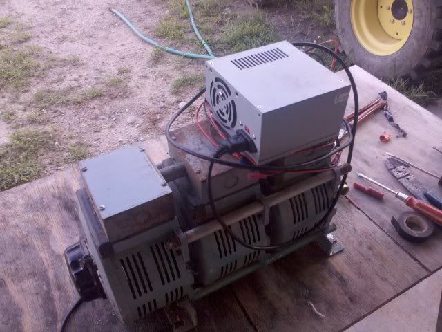
The pc power supply box you see mounted to the top of it is gutted and I have a full wave bridge rectifier mounted to a vary large heatsink inside this. Note that I am only using one transformer out of the gang of 3. It will output around 140 volts and up to 10 amps. The thing is huge and heavy and I will be separating the other two transformers from it soon..:)


Once I am ready to begin the process I use an anodizing calculator that I downloaded from the net (see sample output below). I input the surface area, after a couple of minutes I get my amp reading that the part is drawing at 15 to 16 volts. In this case it would be 1.8 amps. What I am doing throughout the process now is making small adjustments to the variac to keep the amperage at that initial reading of 1.8 amps throughout the 66 minutes. I read that the voltage must be at least 15 volts to get the pore size correct and the amps control how deep they are. With the battery power supply, and the pc power supply my voltages were always to low, at best maybe 12 volts but the amps were within range...however as you pointed out the amps would drop off and it was a constant recalculating process for the time in the tank. So yes, to get the best possible repeatable results a proper power supply is needed.


sampleoutputfromcalculator.gif


The anodizing bath was first mixed at a 1 to 1 ratio. 6 quarts of battery acid to 6 quarts of distilled water. At this ratio and setting the variac to 15 - 16 volts my amps were always higher than what the calculator called for so I was reducing the time needed in the bath by the percentage the amps were over. Last week I added another 2 quarts of battery acid and that seemed to lower the amperage that the parts are drawing at the 15 - 16 volts enough so that I can go by the calculated time.

I am heading to the shop right now to get this next part in. We have some storms moving in our way so I hope we don't loose power when I am half way through the process.

Again thanks for you input. BTW what power supply are you using? Does it allow you to set the voltage and amps separately? Do they stay to your setting throughout the process?
 
A hobby/lab type power supply, on which you can set the amperage to a steady value runs about $100 up to almost $1000.

It all depends on how many amps you desire. I have a small 32 volt 3 amp supply, which costs about $150. For an output around 8 amps you will pay about twice that or more. Approaching an output of 20 amps will put you way up the pay scale.

A VERY pricey item. If you have gotten good results with your method keep at it. Occasional/hobby use means you are probably there to make tweaks to the settings and will be able to maintain a reasonably steady current flow. I understand what babba is saying, but personally think such a rock steady amp flow is only required for commercial size operations.

As long as you are watching and adjusting as things progress,you will get fairly repeatable results.


Secret admirer,
Kermit
 
Thanks Kermit, I have a friend that is into ham radio and he is looking around for a used power supply someone might have laying around...cheap...for now this is working and I have very little invested in it.
 
My power supply is a Skytronic ? ? ? which can output up to 10amps. I'm absolutely hopeless when it comes to Lecktronics so forgive me if I can't be more specific, when I read about technical specs like regulated & ac/dc all I see is #@$$% & @#//*.

I have 2x dials with 2x displays, it's possible to dial in a value for the amps & that then remains constant while the volts do whatever is needed to keep that value steady (& vice-versa with the volts).

It can definately be described as a 'constant current' type power supply but I discovered there are far too many vague definitions & descriptions of the various types of power supplies available during the buying process.

I DO know that it cost me £150, which I consider horrendously expensive for anything with such low numbers but a nephew (who knows about these things) went "wahey" when he saw it & borrows it regularly for various reasons I don't fully understand.

I went through pretty much the same process as you're going through, spent a lot of time fiddling with this & tweaking with that whilst all the time jotting down times & temperatures in as scientific way as I'm capable of.

All I know is non of it made sense untill I was able to control the amps. Once that was in place everything else began to make sense. I can now work out the surface area & do the calc's, bung the item in the bath & 90mins later I have a perfectly anodised prototype which takes the dye like a child takes sweets.
 
Babba,
Thanks for getting back to me. Just one more question if you don't mind. Are you saying that if you set your amps to 2 and your voltage reads lets say 10. You would not be concerned about the lower voltage? I only ask this because I read someplace that 15 volts is recommended. As I recall, I believe the voltage is responsible for the shape/size of the layer...and I believe the abrasion resistance.
 
deere_x475guy said:
Babba,
Thanks for getting back to me. Just one more question if you don't mind. Are you saying that if you set your amps to 2 and your voltage reads lets say 10. You would not be concerned about the lower voltage? I only ask this because I read someplace that 15 volts is recommended. As I recall, I believe the voltage is responsible for the shape/size of the layer...and I believe the abrasion resistance.

I use a '720 rule' calculator I got from somewhere, I tell it the surface area & desired depth of anodise & it tells me what amps to give it for up to 90mins, it also gives me a peak voltage to expect.

What the volts are doing is an indication of whether you're doing it right, the amps are important let the volts do what they want to maintain the amperage.

I have a part that I do 4of at a time regularly, the calculations are 2.2 amps for 90mins with a peak voltage of 16v, I don't bother to monitor the volts unless a batch goes wrong (rare), but if I did, then the voltage 'might' indicate what was wrong. On the few occasions that it has gone wrong it's been down to acid bath temp or loss of connection, what the volts were doing can often point to what went wrong & when. If all's gone well then 'who cares' what the volts were doing?

I also have read that the voltage is important to the growth of the pore, all I can say is that by the rules I'm following, the LCD 720 one, then if the AMPS are OK & everything else is within the boundaries, then the volts will behave themselve's accordingly.
 
That calculator description sounds familiar. I believe I have it bookmaker on my laptop. I will check when I get home this evening.
 
Babba,
I think this might be the calculator you are using.

sampleoutputfromcalculator2.gif


Very similar output to the one I am using.
sampleoutputfromcalculator1.gif


One thing I hadn't thought of before is the one on the top allows you to input a desired thickness for the coating. That might come in hand sometime.
 
The simple law for voltage and current.

Volts divided by Resistance(Ohms) equals Current(Amps)

When you desire to keep the Amps steady, then Volts or Resistance or both can change and as long as the 'math' works out the same the Amps will stay "rock steady".

The resistance of the part you are anodizing is constantly changing by small amounts, so, by the mathematic rules. Voltage will have to change to keep the same Amps flowing.

If the resistance goes up the amps would go down - UNLESS the voltage increases enough to offset the change.

V/R = I That's all these power supplies do. They constantly monitor voltage and amperage and will keep one or the other steady and allow the other to vary to accomplish it.


MORE info:
The acid bath temp and concentration, also the size and spacing of the electrode paddles in relation to the part will have a big effect on how many amps you can push at the low voltages being used. If you have two feet between the electrodes and a part that is one foot long. The ends of the part will receive more electricity(amps) than the middle of the part. Simply because it is farther away from the electrodes and therefor has more resistance to overcome due to the longer distance to the electrodes. Likewise, parts with lots of surface area would benefit from an increase of electrode surface being used. Lower current density on the electrodes than on the part is a good thing(within reason)

The above is my condensed version of all the tech rules I've read on this subject over the years.
Kermit

 
Thanks Kermit, lots of variables come into play with this and you have helped to pull a few of them out for this thread so others reading it can understand also... My current setup allows me to manually adjust so that I can keep the current steady. I couldn't do that before and while it worked for the most part it was a bit of a guessing game to determine when the anodizing was complete. I tried to pay attention to when the amps started to climb figuring I was at PAR. This didn't always work for me.
 

Latest posts

Back
Top