Alibre 2012

Home Model Engine Machinist Forum

Help Support Home Model Engine Machinist Forum:

This site may earn a commission from merchant affiliate links, including eBay, Amazon, and others.
One of the unusual things about 3D software is that it seems to be a little more inconsistent than 2D software.

I can use a command several times in a row, and it works perfectly, and then the same command stops working, then later, it may start working again.

3D programs are much more finicky than 2D, and sometimes you have to be creative about using an alternate approach. 3D is not cut and dried like 2D.

3D is also a much more complex process than 2D, and so it really tends to bring out any bugs in the software (all 3D programs have bugs, you have to work around them).

I have tried to keep passages simple. For curved steam passages, I draw the section first using a spline. Then I extrude that curved shape from a midplane out, and then fillet it.

For the exhaust passage, I have to build up several different features onto the original spine extrusion, in order to wrap the exhaust around the cylinder before it exits the cylinder.

Sounds like you could break your passages down into parts, and extrude one part at a time, and then fillet the corners.

Sometimes I build up passages from several different extrusions, and then go back and cut off parts that I don't want.

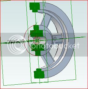
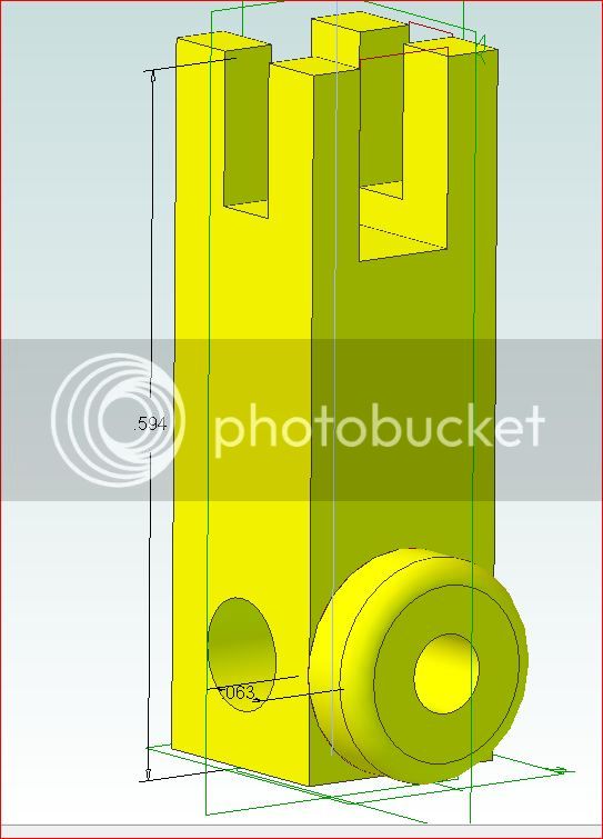
Below is an example of steam and exhaust ports/passages.

I have not used gears in Solidworks, so I can comment on that.
Haven't done cam followers either, but I would assume they would work correctly. I will play with that and try to check it out.

Cylinder-Cores-02.jpg


Cylinder-Cores-01.jpg


Final-Cylinder-14.jpg
 
Sometimes I build up passages from several different extrusions, and then go back and cut off parts that I don't want.

Thank you for your reply and examples, I think you're right, that must be the way to do it, if I want them better than what I accomplished do far.
 
UNIcastings said:
I have not used gears in Solidworks, so I can comment on that.
Haven't done cam followers either, but I would assume they would work correctly. I will play with that and try to check it out.

Hello,

I have Alibre as well (have been a user since V9). I believe (I don't have Expert) the Expert version of the software allows for the gears to mesh and move. I use the product for personal use so I didn't spend the money on Expert level but I remember seeing a demo of the V11 product with a gear train moving etc.

I also had SolidWorks installed (2010 I think) at one point to compare, but it was the full blown version and it supported motion much better than Alibre did at the time. But I wanted to be legal so I kept with Alibre which does 98% of what I need.

I also miss the SolidWorks ability to edit the 3D model and have the drawing update instantly.

Jeff
 
I had the cheap version of Alibre v10 and believed that the Pro version worked with gears, so when I had a cheap offer to upgrade to Alibre Design Pro 2012, I did and discovered that gears and cam following is in the Motion Package at a lot higher price :(

I'm told that is a way to cheat Alibre into turn simple spur gears, but it doesn't always work ....

I've got two main reasons for using Alibre - designing model engines and discover my errors before I commit to metal, and construct parts for my motorcycle, The first is a bit of a drag without being able to check the valve train in a four-stroke. I'll have to learn the cheat and hope that it helps me solve any cam related problems.
 
There are a couple of Alibre forums that I have found to be very helpful. Try a Google search for them.

Jim
 
Another nice thing you can do with 3D modeling (if you learn how to add machining tolerances, fillets and draft angles) is to print your design on a 3D printer (or have someone print it for you), and then cast your own engine.

3D printers are definitely not ready for prime time, but in the next few years, I think that technology will mature, and it will become easier.

Making your own casting kits is really a lot of fun, and you can make the design any way you want it (correctly I hope).

A few photos below from the TB5 engine.

I think if I had used 3D modeling and casting on the TB5 engine, I would have avoided a lot of the problems I am having now with using built-up construction.


Assembly-05.jpg


rIMG_2358.JPG


rIMG_2390.JPG


rIMG_2412.JPG
 
AussieJimG said:
There are a couple of Alibre forums that I have found to be very helpful. Try a Google search for them.

Jim

The problem I had with 3D forums is that I could not find a forum that specifically designed steam engines, and so it was difficult to figure out how to apply things to what I was trying to do.
 
Here is a quick mock-up I did of some columns for one of Stew's engines a while back.

Gears are made in a similar fashion.

Stew-04.jpg


Stew-02.jpg
 
UNI
I am a Alibre user from day one when they rolled it out. I now have a 3D printer that I will be using to make molds for wax patterns for the model steam engines I will be building, will also use it for molds for model boat propulsion systems I build.
here is a link to the forum for the printer I have http://forum.seemecnc.com/index.php

here is a link to the printer http://shop.seemecnc.com/

3D printing is coming down in price and they are getting better on quality of print. Not a comercial machine but I do not have $20k to spend on one.

Dave


UNIcastings said:
Another nice thing you can do with 3D modeling (if you learn how to add machining tolerances, fillets and draft angles) is to print your design on a 3D printer (or have someone print it for you), and then cast your own engine.

3D printers are definitely not ready for prime time, but in the next few years, I think that technology will mature, and it will become easier.

Making your own casting kits is really a lot of fun, and you can make the design any way you want it (correctly I hope).

A few photos below from the TB5 engine.

I think if I had used 3D modeling and casting on the TB5 engine, I would have avoided a lot of the problems I am having now with using built-up construction.
 
The biggest problems I have with 3D printing right now are:

1. Print area can be too small (depends on your model size).
2. The program takes too long to generate the code that you feed into the printer (you have to generate this code for every part, and sometimes the code does not turn out right).
3. The plastic material for some printers is relatively inexpensive, but some of it does not last very long if exposed to air, it can get brittle if not sealed in an airtight container. Some of it is not UV resistant either.
4. The parts that you print can get brittle quickly.
5. Some of the various plastics have a high shrinkage rate, so caution needs to be used if you plan on printing a pattern.
6. Some printers have difficulties with getting the mat started and keeping the mat flat and adhered to the printing surface, and also adhered to the printed part, but not adhered so much that you can't peel the mat off.

These problems seem to apply especially to the inexpensive printers.
The $25 K printers don't seem to have these problems, but most would not even be able to afford the plastic material, much less the expensive printers.

Plastic material for the good printers makes gold seem like a cheap commodity (really).

 
I looked at the new features in Aibre 2012.

The "Project sketch-to-sketch" is the only thing that looks really useful as far as modeling engines, but this item is a big time saver.

 
UNIcastings said:
The biggest problems I have with 3D printing right now are:

1. Print area can be too small (depends on your model size).

Print area on my machine is 7.5"x7.5" by 5" tall. This can be a problem if your prints are bigger than your print area. I have the same problem with my milling machine
2. The program takes too long to generate the code that you feed into the printer (you have to generate this code for every part, and sometimes the code does not turn out right).

I use a program called Slic3r for generating my Gcode. The test cube you see is 40X40X40mm and took about 4 minutes to generate the code.
3. The plastic material for some printers is relatively inexpensive, but some of it does not last very long if exposed to air, it can get brittle if not sealed in an airtight container. Some of it is not UV resistant either.

I print using black ABS. I pay $17.5/pound. It is very stable
4. The parts that you print can get brittle quickly.

I don't thing ABS suffers from this problem.
5. Some of the various plastics have a high shrinkage rate, so caution needs to be used if you plan on printing a pattern.

I have not found shrinkage to be a problem with ABS. I am sure there are other plastics that are more prone to shrinkage.
6. Some printers have difficulties with getting the mat started and keeping the mat flat and adhered to the printing surface, and also adhered to the printed part, but not adhered so much that you can't peel the mat off.

ABS has a problem sticking to a cold print bed. Lots of folks are running heated print beds to get over this. I am working on my heated bed.

These problems seem to apply especially to the inexpensive printers.
The $25 K printers don't seem to have these problems, but most would not even be able to afford the plastic material, much less the expensive printers.

Yes I have a friend that owns comercial machines and pays over $4000 per year in maintance.

Plastic material for the good printers makes gold seem like a cheap commodity (really).

Here is a test cube I printed today. It is 40x40x40mm as drawn. printed at40.1x40.40x39.88mm That is .0041"x.0157" big and .0048" short. Not to bad I think.

100_1200.jpg


100_1199.jpg


Dave

 
I love it when folks chime in and contribute.
As far as the albre goes I spent a good part of the day drawing. did somthing like 6or 8 parts of a redraw of the elmers 41 Factory engine. My version I gues one would say. the crank disk was a pain. Base sub base floor all easy and went well and I loved alibre for drawing the little fork . a tiny part but easy to draw. I only hope machining will be as easy.
A good day.
Tin
 
talking of Alibre, any one been using there cam software? and im not on about the 2.5 axis cam that comes with Alibre cad. think its the same as Visual mill, but they call it Alibre cam.
 
I have not seen or used the cam software.
What does it do?

Tin-

Are you going to post some screen shots of you 3D work.
I am sure others would want to follow along with what you are doing/learning.

I use the "print-screen" button on the keyboard, and then paste into a photoshop program, to get screenshots.

 
blighty said:
you use CAM software to generate tool paths, that will then generate a g-code that you load up to your CNC mill/lathe etc.

Oh, I see. I thought it had something to do with a CAMera.

Nice models Tin!
 
Thanks for the complements pat. I am pretty happy with the results.
A few thinks I learned the hard way
1) the part configuration menu is hidden behind the Albre Jewel it used to be under file basically the same spot on the screen but somewhat hidden.
2) if you select another Plane beside the default xy to sketch on you need to also select orient to sketch plane.
3) seems like you have to exit sketch mode to go back and edit a sketch
4) some time it is easier to start over than fix something that is not working.

I still have a lit to learn I have yet to tackle assembles.
there are still a lot of basics to pick up on.

But I am moving forward.
and another model

41fork.jpg

Tin
PS I used my snipping tool and saved to a jpeg. then upload to Photobucket.
 
Tin-

When I first started using 3D, I remember I would generally get 1/2 to 3/4 of the way done, and then hopelessly botch the part and ruin the model beyond repair (much like my machining these days).

It was very frustrating. It seemed like I could never predict what the program would do next, but I didn't really have a feel for jumping on and off the various sketch planes, orienting the sketch planes normal to the screen, or editing existing sketches from the side menu.

As a work-around, I would make a sketch, extrude it, and then save it as "File-01". Then make a second sketch, extrude it, then save as "File-02", etc. A new file for every added sketch/feature. Then when I botched the part, I would just open the previous file, and try it again.

I finally got to where I only need one file, and I can fix anything in any file. It took a while though.

Solidworks starts a part in sketch mode, and when you use a 3D feature, it jumps out of sketch mode, thus setting you up for selecting the next plane to begin sketching on. This was very confusing for a while.
If you can get the "sketch-mode" and "not-sketch mode" down, and understand when and why to be in which mode, then you can make a whole lot of progress very quickly after that.


Latest posts

Back
Top