


I've had an old 1959 9" Craftsman Radial Arm Saw for quite awhile now, but it never had the anti-kick-back device for ripping. I've ripped lot's of boards without it but finally decided to make one.
There's probably several ways to go about this, but I wanted to use the rotary table.
I broke out my 3" rotary table and plopped it on the mill table. I've never really used it much so here's some pictures.

First I drew a picture in AutoCad and used Ordinate Dimensioning with the center of the stock as 0,0,0"
My plan was to create the shape for the pawl on the face of the round stock, then part off two slices when done. The diameter is 1.8125" and it's cold roll steel. The endmill is 3/4".
I started out with my 4" lathe chuck screwed onto the rotary table adapter to hold the piece, but that was way too tall for what I was trying to do. I gave up on that setup as it was too scary.
I cobbled together some odds and ends and went straight onto the little 3" faceplate. Looks odd, but it was solid as a rock. I used emory paper under the work piece for anti-skid.
I drilled two 1/4" holes first. One for the pawl pivot, and the other where I planned to plunge the endmill in .350" for the inner curve shape.
I was supprised at how well the X3 mill did the 3/4" plunge cut.
Once the plunge cut finished, I offset the cutter and plowed across the face. I used slow ~60rpm speeds and .010" depth/cut. It felt like it could do even more, but I didn't want to get in a hurry/screw up.
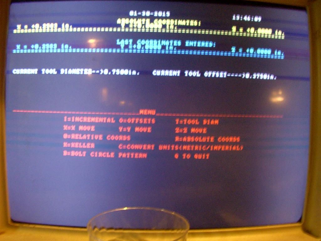
I used my home made DOS program for XYZ readouts (manual inputs off the scales) since it does the math and offsets for me. You just have to do the move on the keyboard, before the actual machine move to get your targets.
The little 3" RT did great. I did use a flat blade screwdriver on the little table lock screw though to cinch it down good.
Here I'm breaking down the job. Note the little "fence" I used to align the table for 0 degrees for the X-axis.
http://
I didn't have any 5/16" hardware for clamping the table to the mill so that's why there's so many pieces on the table. Those mounting slots are tiny. I'll open them up to 3/8" soon.
Tomorrow I'll part off the two pieces and remount them on the RT one at a time to round the ends. No pics yet on that. I needed to run a tap through the center hole on the table since the factory didn't thread it all the way through to the top side of the table for a center hold-down. I think it was 7mm I don't remember.
I hope to get some use out of this little cheapo RT.
http://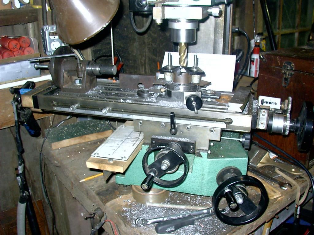
Rich
There's probably several ways to go about this, but I wanted to use the rotary table.
I broke out my 3" rotary table and plopped it on the mill table. I've never really used it much so here's some pictures.

First I drew a picture in AutoCad and used Ordinate Dimensioning with the center of the stock as 0,0,0"
My plan was to create the shape for the pawl on the face of the round stock, then part off two slices when done. The diameter is 1.8125" and it's cold roll steel. The endmill is 3/4".
I started out with my 4" lathe chuck screwed onto the rotary table adapter to hold the piece, but that was way too tall for what I was trying to do. I gave up on that setup as it was too scary.
I cobbled together some odds and ends and went straight onto the little 3" faceplate. Looks odd, but it was solid as a rock. I used emory paper under the work piece for anti-skid.
I drilled two 1/4" holes first. One for the pawl pivot, and the other where I planned to plunge the endmill in .350" for the inner curve shape.
I was supprised at how well the X3 mill did the 3/4" plunge cut.
Once the plunge cut finished, I offset the cutter and plowed across the face. I used slow ~60rpm speeds and .010" depth/cut. It felt like it could do even more, but I didn't want to get in a hurry/screw up.
I used my home made DOS program for XYZ readouts (manual inputs off the scales) since it does the math and offsets for me. You just have to do the move on the keyboard, before the actual machine move to get your targets.

The little 3" RT did great. I did use a flat blade screwdriver on the little table lock screw though to cinch it down good.
Here I'm breaking down the job. Note the little "fence" I used to align the table for 0 degrees for the X-axis.
http://

I didn't have any 5/16" hardware for clamping the table to the mill so that's why there's so many pieces on the table. Those mounting slots are tiny. I'll open them up to 3/8" soon.
Tomorrow I'll part off the two pieces and remount them on the RT one at a time to round the ends. No pics yet on that. I needed to run a tap through the center hole on the table since the factory didn't thread it all the way through to the top side of the table for a center hold-down. I think it was 7mm I don't remember.
I hope to get some use out of this little cheapo RT.
http://

Rich


