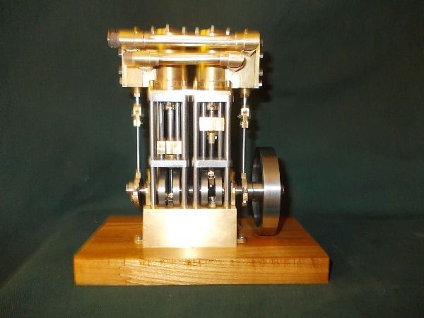
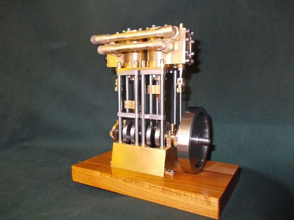
A Two Cylinder Steam Engine

Home Model Engine Machinist Forum

Help Support Home Model Engine Machinist Forum:

This site may earn a commission from merchant affiliate links, including eBay, Amazon, and others.
Hi RodW.

I dont have collets on my lathe and have been meaning to look for some and of course, to weigh the cost. However in the case of my screws I dont see why I would have saved time with respect to using a 3-jaw self-centering chuck. In my mind collets contribute accuracy rather than speed.

The collet block I was thinking of is a hexagonal block that holds a collet in the centre so you would not use the collet in the lathe chuck. Then you can just fix the 6 sided block, rotating it to mill each side, with an appropriate back stop to keep position but then maybe you don't have a mill? But it might work milling on the lathe perhaps? That's why I said I wasn't sure if it would help. The block kits themselves are not that expensive, about $30 in the US which of course becomes $90 in the Southern Hemisphere!

I often make parts in batches of 100-200 and am always looking for ways to make it easier but my parts are nowhere near as complex as yours and I was amazed by your resourcefulness to get the detail right!
 
GKNIPP said:
I was wondering if I missed the PDF drawings for the eccentrics and flywheel? Maybe I scrolled right past them?
Hi Greg. The three PDFs for all the parts of the Shaft Assembly are attached to the first post which talks about the Shaft Assembly i.e. Post #5 which is on Page #1 of the thread.
 
RodW said:
The collet block I was thinking of is a hexagonal block that holds a collet in the centre so you would not use the collet in the lathe chuck.
RodW, Thank you for this suggestion. I didn't know about Collet Blocks and will bear them in mind from now on. Using one to mill (in my lathe) the flats of the hexagons of my bolts would probably have saved a bit of time with respect to hand filing them.
 
[SIZE=+2]
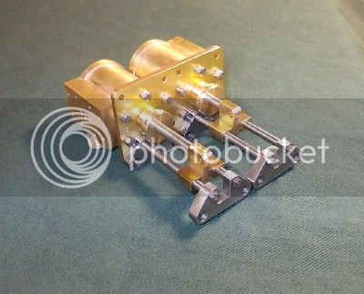
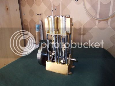
THE CYLINDER ASSEMBLY - 3. Cylinder Unit - 1[/SIZE]

This post reports on the building of the three sub-parts of which each of the Cylinder Units is composed. The following post will cover the soldering of these parts and the finish machining of the soldered Cylinder Units.
The drawings of all the parts of the Cylinder Units are attached to the first post on the Cylinder Assembly.

DESIGN CONSIDERATIONS

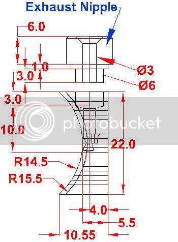
The Cylinder Units are built by silver soldering three brass parts namely a Cylinder Tube, a Cylinder Face, and an Exhaust Nipple. Most aspects of the design have been mentioned in the introductory post to the Cylinder Assembly and so I will not repeat them here.

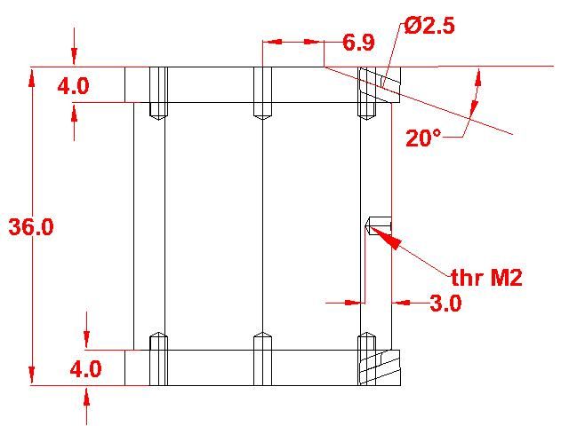
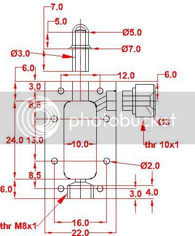
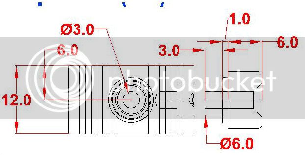
With respect to the design shown on the drawings, I decided one change. The steam channels linking the live Steam Ports to the holes through the cylinder walls will be milled into the curved arc of the Cylinder Face and not into the wall of the Cylinders. The reason for this change is to facilitate the flow of molten silver solder, bearing in mind that the position for soldering will have the Cylinder Tubes lying horizontally with the Cylinder Faces resting on top of them.

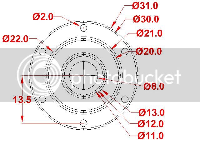
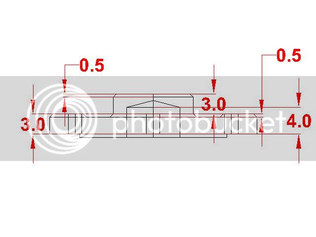
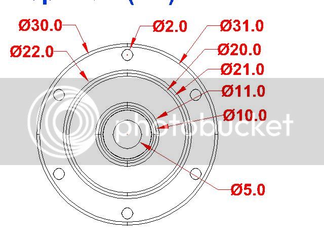
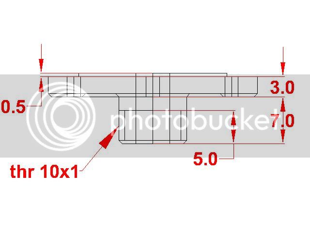
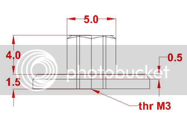
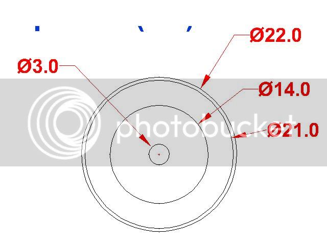
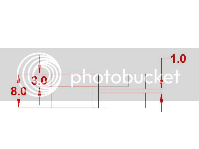
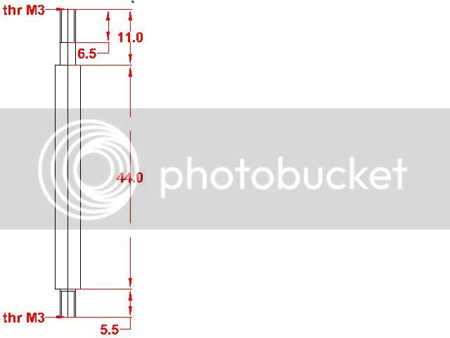
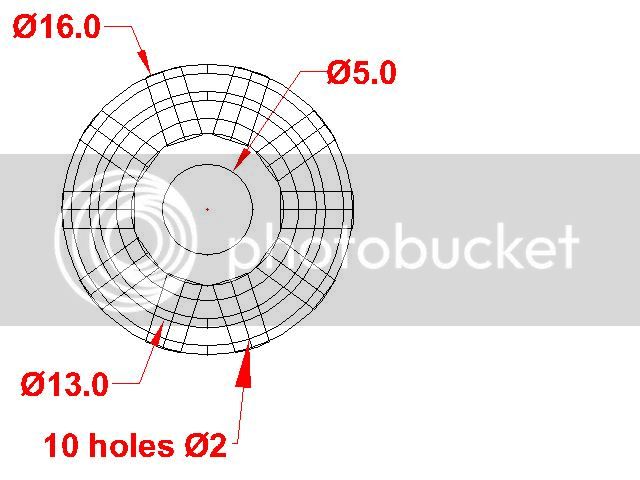
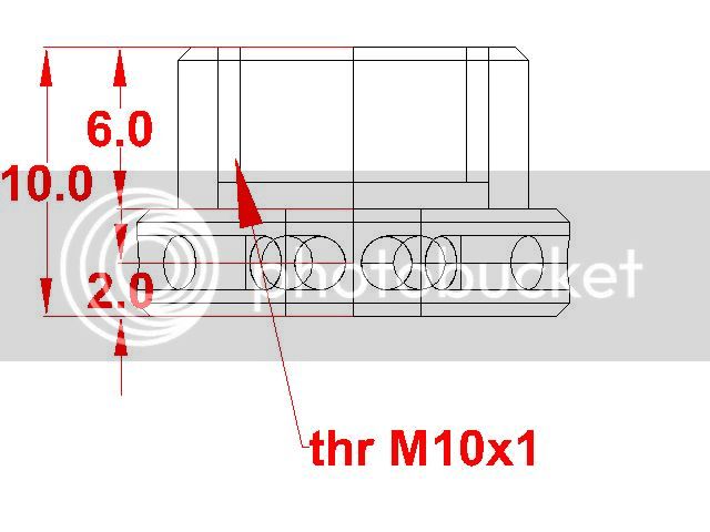
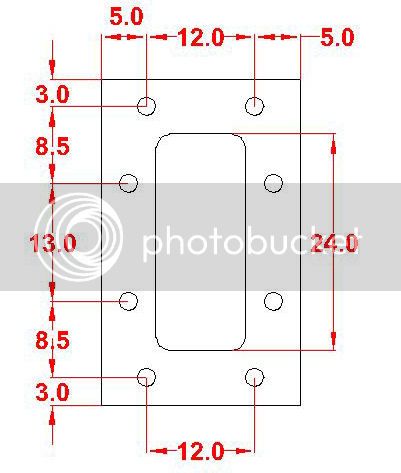
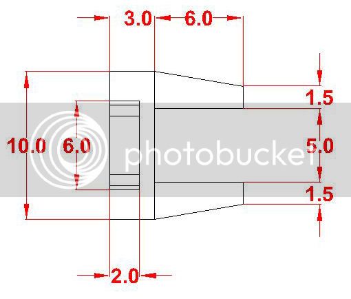
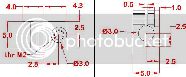
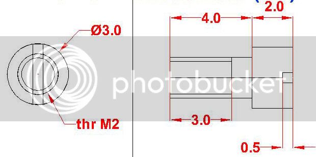
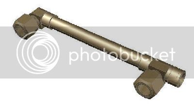
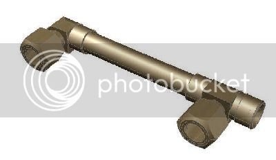
Here are some extracts from the updated drawings.
CYACU00CylDwgFront_zps26a9abb1.jpg
CYACU00CylDwgTopjpg_zpsc96245ed.jpg

CYACU00FaceDwgTop_zps8c2a2db3.jpg
CYACU00FaceDwgFront_zps442bf963.jpg


BUILD APPROACH

Overall Criteria


There were three important criteria for the formulation of the approach to the build.
  1. Do as much final machining as possible after soldering.

    More precisely, try to limit the finish machining before soldering to surfaces which are going to be in contact for soldering. However there are surfaces which are not contact surfaces to be soldered but which would be very difficult to machine after soldering. In the case of the Cylinder Unit this is true of:
    • those portions of external wall of the Cylinder Tube wall which are not in contact with the Cylinder Face;
    • the front and rear faces of the Cylinder Face;
    • the threaded portion of the Exhaust Nipple;
    • the steam passages milled into the rear surface of the Cylinder Face.
    Thus the surfaces to be finished machined after soldering are:
    • Cylinder Tube: the bore and the upper and lower faces to the covers
    • Cylinder Face: The Face itself and the upper and lower edges
    For all these surfaces the preliminary machining in preparation for soldering must leave excees material (roughly 0.5mm) to be removed after soldering.
  2. Limit the oxidization of surfaces to be soldered both by reducing as much as possible the elapsed time between preparing the surfaces and actually doing the soldering and by keeping the parts in plstic bags during the waiting time
    Brass surfaces oxidize and the solder does not take to the oxide layer. So for surfaces which are not to easy to brush up before soldering, it is important to minimize the oxidation by limiting the waiting time and/or the oxygen before soldering.
  3. The three parts to be soldered must be held in position firmly during soldering.
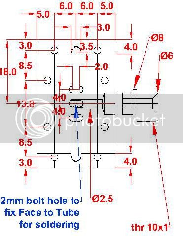
    Remember that for silver soldering the fit between contact surfaces must be neither too tight nor too loose; silver solder requires a bit of space (a few thou) but not too much to work it's capilary magic. The Exhaust Nipples can be made to hold themselves in the holes of the Cylnder Face by making one or two small bumps on their surfaces with a punch. Holding the Cylinder Face and the Cylinder Tube together in the right position needs a bit more ingenuity; I decided to use a sacrificial 2mm brass bolt which passes through the Cylinder Face in what later will become the exhaust port and which screws into a shallow (3mm) threaded hole in the Cylinder Tube wall (which will be 3.5mm thick after finish machining).
Preparing the Cylinder Face

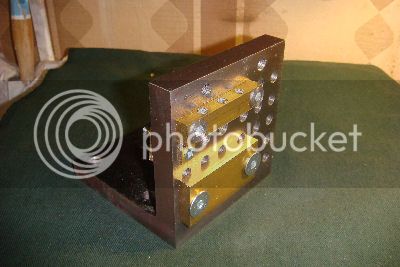
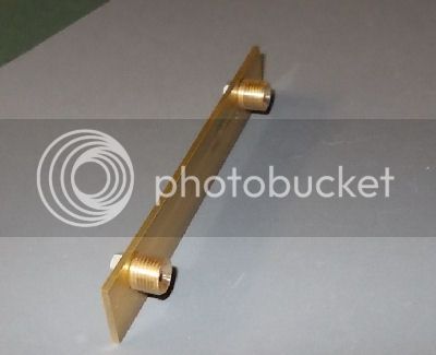
The only difficult part to prepare for soldering is the Cylinder Face, because it requires final machining of it's stepped curved surface which makes contact with the outer surface of the Cylinder Tube wall. After considering various alternatives I decided to use a boring bar between centers and to mount the Cylinder Face on the upper surface of the cross slide not below the boring bar as I have done on other occasions but behind the boring bar so that the center line of the Cylinder face is at the same height as the lathe's axis. To do this I used a robust 90 deg angle plate on which I mounted a pair of brass "jaws" and a small brass End Stop. The upper edge of the lower jaw is at exactly the right height (ie 11 mm lower than the lathe's spindle axis). The upper jaw has three 6mm grubscrews to hold the Cylinder Face in place during machining (with a piece of protecting brass between the screws and the work piece).

CYACU01Jig_zps825704bb.jpg


This arrangement gives me big advantages:
  • I can use the boring bar itself to ensure that the face of the angle plate is parallel to the lathe's splindle axis. Knowing the radius of the boring bar (10mm) I can then set the zero of the cross slide index dial.
  • I can then use the face of the angle plate to adjust the radius of the arc described by the cutter. For example the smaller arc has a radius of 14.5mm; so I set the angle plate to be at 4.5mm from the boring bar and then adjust the cutter to just touch without marking the angle plate.
  • I can use the movement and index dial of the cross slide to vary and control the distance of the Cylinder Face from the cutter, both for setting the depth of cut and for doing the final cut with the axis of the Cylinder Face curves exactly coinciding with the spindle axis of the lathe.
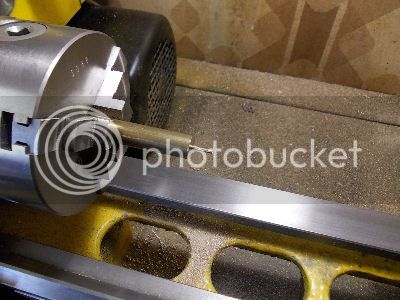
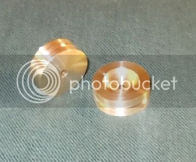
To check the radii of the two outer sections (radius 15.5mm) and the single inner section (radius 14.5mm), I plan to prepare from scrap brass rod two short cylinders with appropriate diameters.
The two outer sections can be prepared using the same tool and without altering its radius setting simply by reversing the boring bar between the centers (i.e the head end becomes the tailstock end and vice versa) and then making the lathe spindle rotate backwards. This is perfectly safe on my lathe because the working interface of the lathe spindle is a bayonet and not a thread.

BUILD LOG

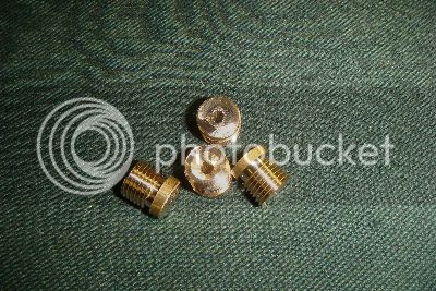
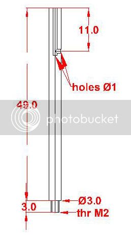
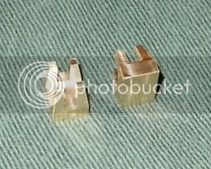
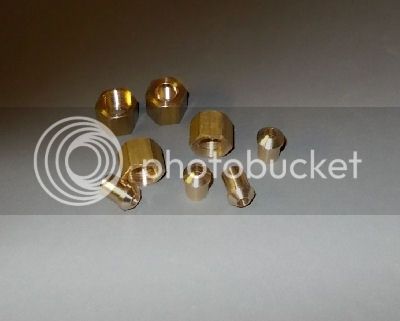
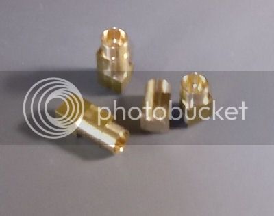
Exhaust Nipples - non contact surfaces

First I prepared the non contact surfaces of the nipples. While at it I made four because the live steam nipples are the same. The contact surfaces will be machined nearer to soldering time...
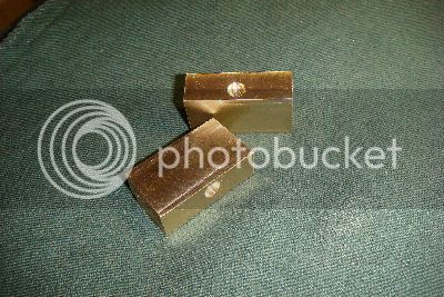
CYACU02NipplesHalfDone_zpsaaf0d1f7.jpg


Cylinder Faces
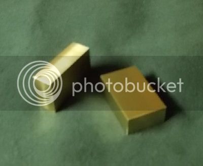
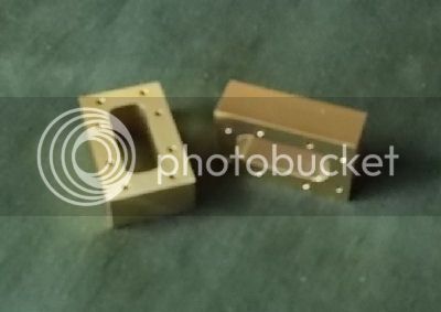
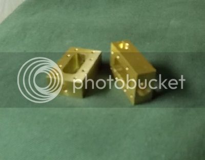
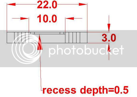
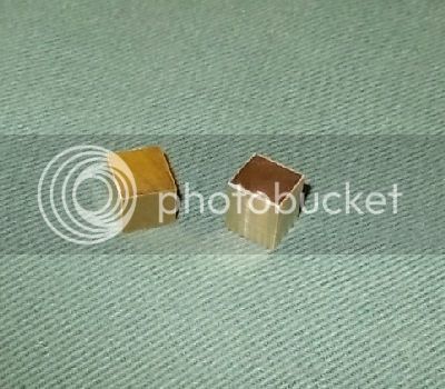
Then I started the pre-soldering machining of the Cylinder faces. The two rectangular blocks shown in the image below were recovered by milling away the excess from two pieces from the 25mm brass rod. The width (22mm) is final size but the thickness (10.55mm) and the height (36mm) have at least 1.5mm of excess material.

For both thickness and height one of the two faces is chosen as the reference face and the excess material on it is taken to be exactly 0.5mm. Bearing this in mind the exhaust passage and the 6mm hole to receive the Exhaust Nipple were positioned and drilled.
CYACU03FacesDeforeArcs_zps08d8cb2e.jpg


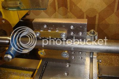
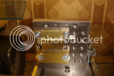
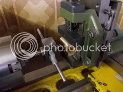
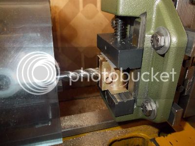
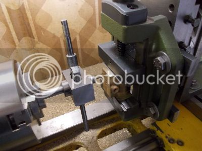
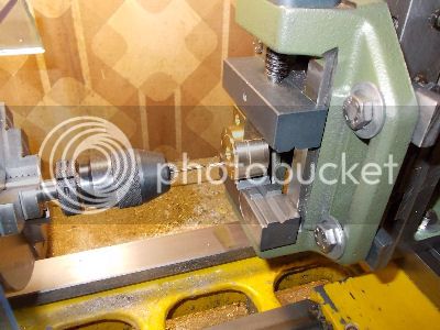
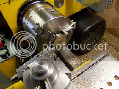
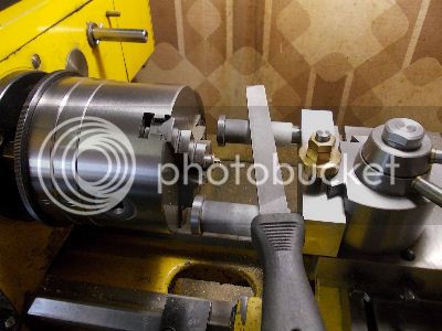
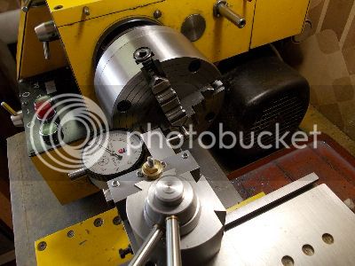
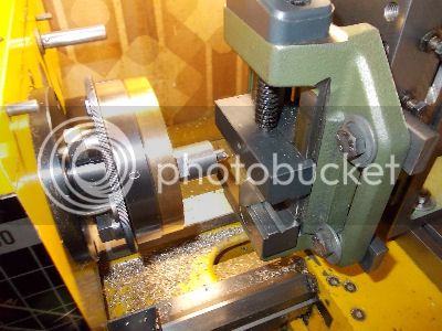
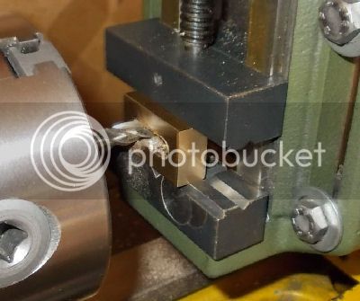
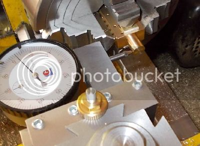
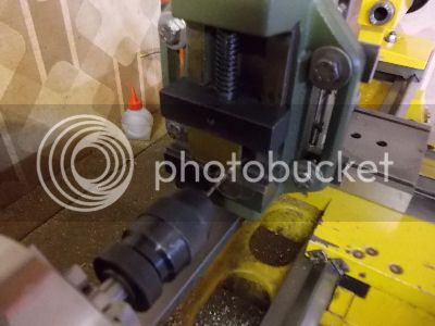
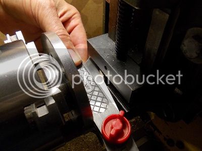
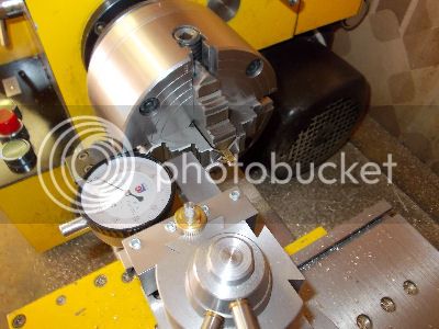
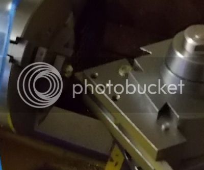
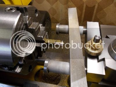
Now it was time to use the jig for making the arcs. Here is the boring bar being used to set up the jig with the face of the angle plate parallel to the lathe axis.
CYACU04SettingPlateSquare_zps1fc5ab7f.jpg


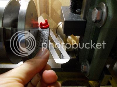
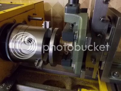
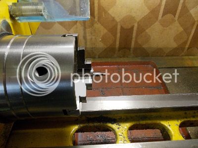
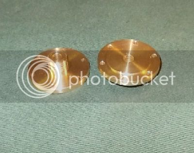
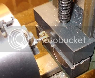
This phote shows the first Cylinder Face with the central arc (radius 14.5mm) finished so that the outer face of the Cylinder Face (ie the face of the angle plate) at exactly 20.5mm from the lathe axis. (The extra 0.5mm will be removed after soldering).
CYACU05CenterArcDone_zps2996f381.jpg


Before proceeding with the outer arcs of the first cylinder, I made the central arc of the second Cylinder face.

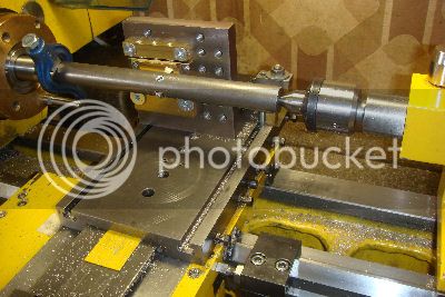
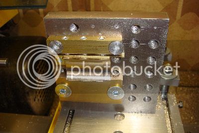
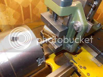
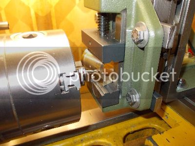
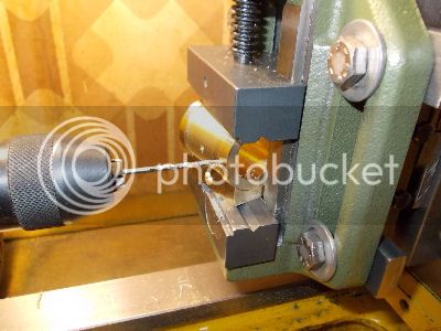
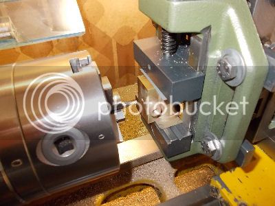
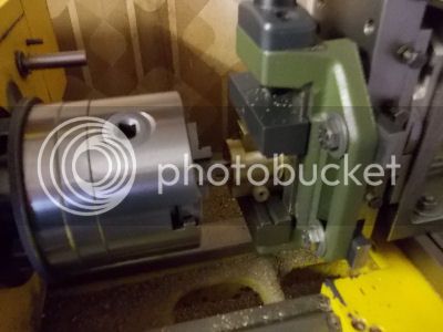
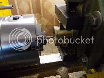
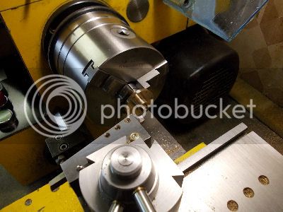
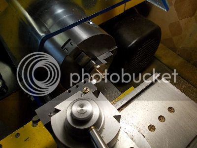
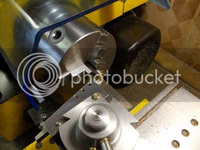
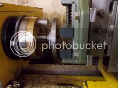
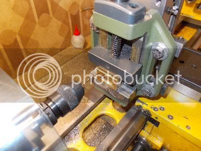
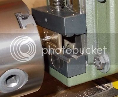
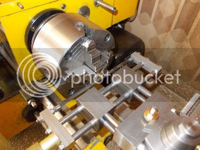
These central arcs were the easy ones; the outer arcs require more attention! With no Cylinder face in the jig, the boring bar cutter was adjusted to have a radius of 15.5 mm and the lathe's carriage stop was moved to the right of the carriage and set so that rightward movement of the carriage would be blocked when the cutter edge was exactly 32.5mm from the End Stop of the jig. The first Cylinder face was then mounted with the reference end up against the End Stop. In this position the right end outer arc was machined again making sure that the last cut was with the face of the angle plate at 20.5mm from the lathe axis. The next two photos show the setup (note the carraige stop) and the result (with the boring bar out of the way).
CYACU06FaceRightArc_zpsb62123c4.jpg

CYACU07RightArcDone_zpsbda042b8.jpg


I then removed the first Cylinder Face from the jig and repeated the operation for the second one.

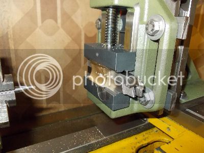
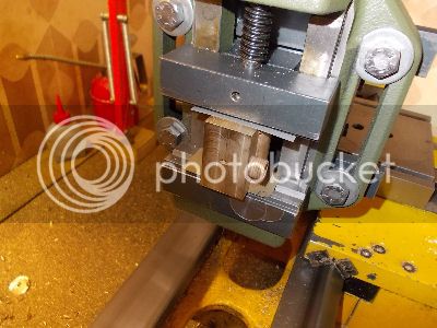
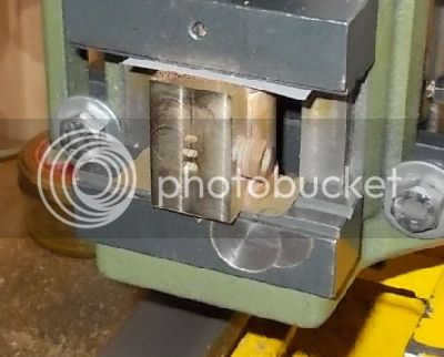
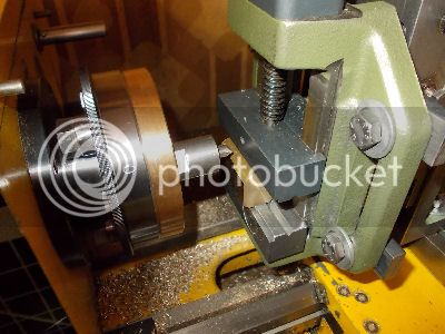
To do the left end outer arcs the secong Cylinder Face was removed from the jig, the carriage stop was restored to the usual side of the carriage and, without altering the setting of the cutter, the dog was moved to the opposite end of the boring bar which was in consequence reversed ie its cutting edge was on the right and had to move downwards to do the cutting. The carriage stop was set so that leftward movement of the carriage would be blocked when the cutter's edge was 4.5 mm from the End Stop of the jig. The first Cylinder face was then remounted in the jig again with its reference end up against the jig's end stop. In this position the right end outer arc was machined again making sure that the last cut was with the face of the angle plate at 20.5mm from the lathe axis. The phote shows the setup with the cutter in this upside down position.
CYACU08FaceLeftArc_zps68bbe465.jpg


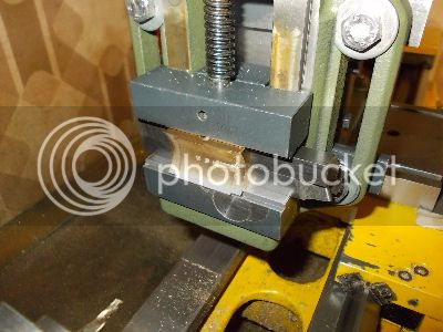
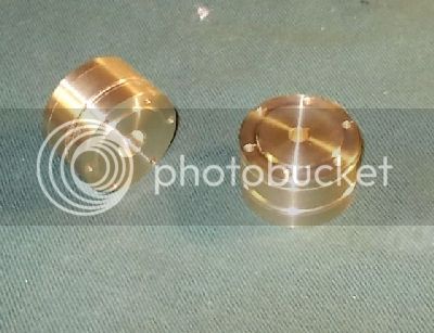
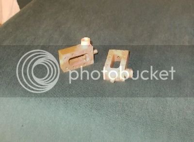
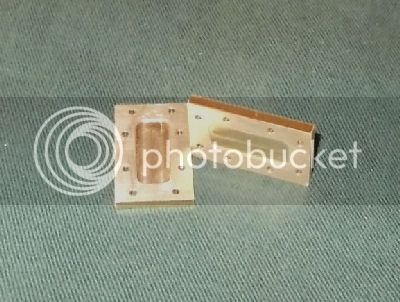
Then the same again for the other Cylinder Face. Here you see the two Cylinder Faces at this stage of the game. Before soldering they still need a bit of milling but that will wait until it can be done with the same milling lathe setup as the Cylinders.
CYACU09FacesWithArcs_zps9976acd8.jpg


Turning the Cylinder Tubes

The Cylinder Tubes are machined from two bits of 32mm brass rod; I cut these bits long enough so that I can also make the upper and lower flanges for the cylinders. The first step was to face off the end and then drill and bore to a depth of 39mm a hole of diameter 21mm (i.e. 1 mm less than the final diameter of the cylinder bores.
CYACU11CylDrillingBore_zps4f90ee53.jpg

CYACU12CylBoringBore_zpsa92dc6cb.jpg


Then the outer diameter of the Cylinder Tube rims was machined to final size (diameter 31mm). This are a contact surfaces for soldereing so one must remember to avoid touching them.
CYACU13CylRims_zpsd469cde3.jpg


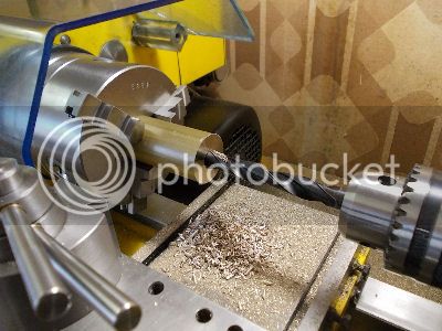
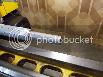
The lathe carriage stop was then set so that leftward movement of the carriage would be blocked with the tool cutting edge at 32.5mm from the face. To make this measurement I use the index dial of the compound slide. Then the machining was done with the knife tool gradually increasing the depth of cut as the carriage advanced. After four passes with a maximum cut depth of 0.25mm I had the result shown in the next pic: a shallow cone starting near the right end and ending about 6mm short of the position defined by the carriage stop. These last 6mm have their final diameter of 29mm.
CYACU14CylWall_zpsaa0532c7.jpg


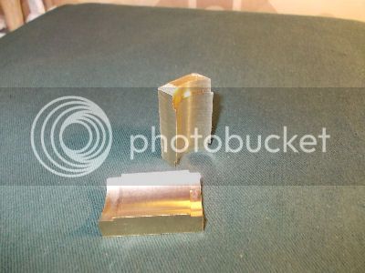
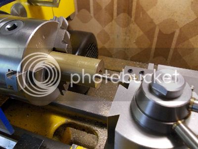
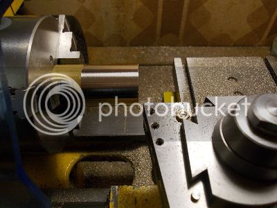
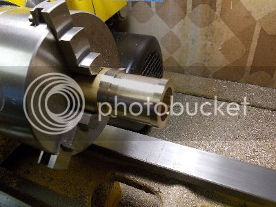
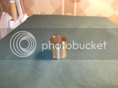
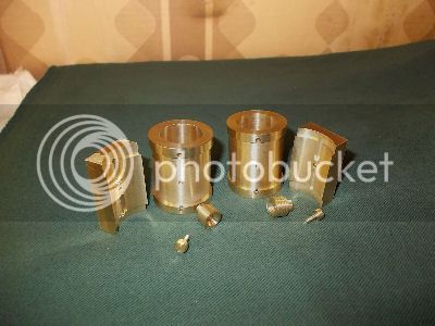
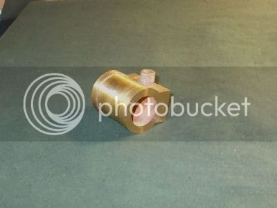
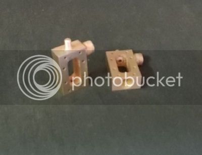
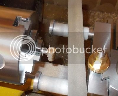
The job was then completed in a similar fashion using a right shouldered knife tool with the carriage stop on the right of the carruage up to a shoulder 4.5mm to the left of the cylinder end. Here is the result; the Cylinder Tube on it's own and then the Cylinder Tube with a Cylinder Face perched on top of it.
CYACU15CylFaceInterface_zps08861d07.jpg

CYACU16CylWithFace_zpsc6fa0a70.jpg


The final turning step was of course to part the Cylinder Tube off for an over length of about 37mm i.e. about 0.5mm of excess material at each end.
CYACU17CylTurningDone_zps2d86ea36.jpg


I then did all this over again for the second Cylinder Tube. Before soldering both Cylinder Tubes still require machining with the lathe in it's milling configuration.

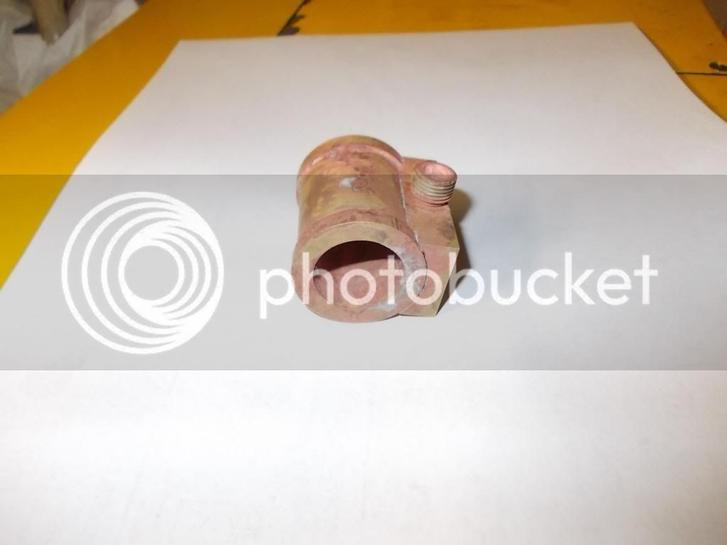
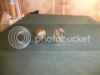
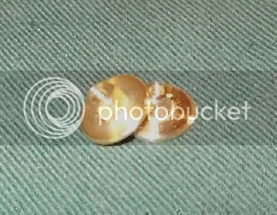
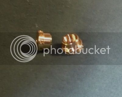
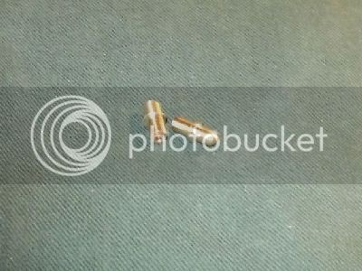
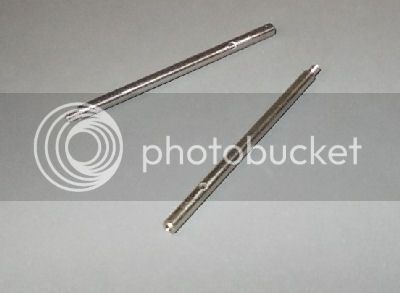
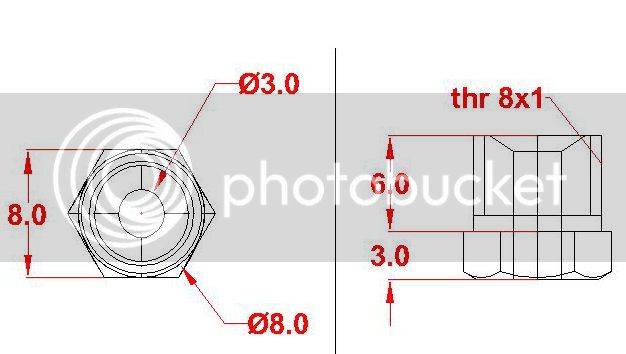
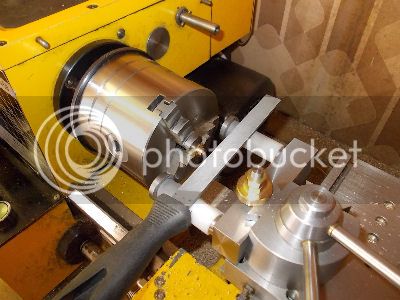
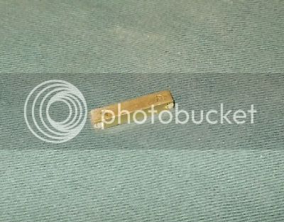
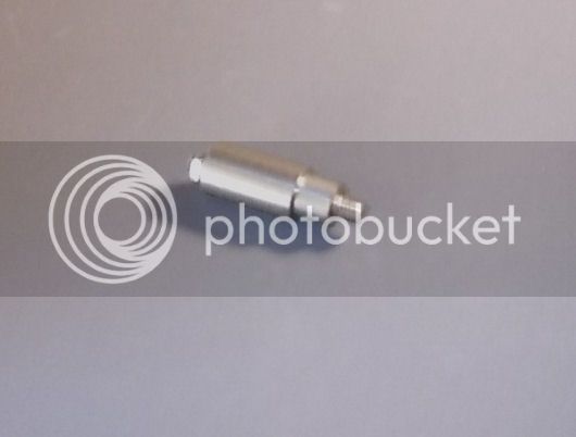
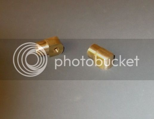
Finishing the Exhaust Nipples

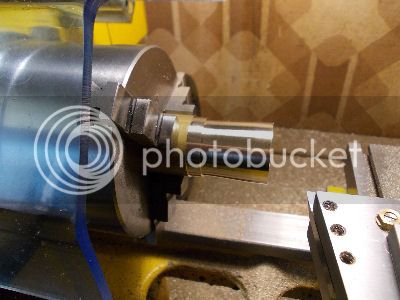
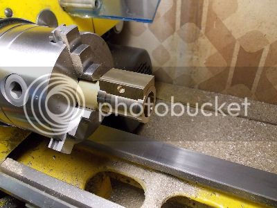
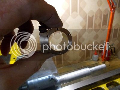
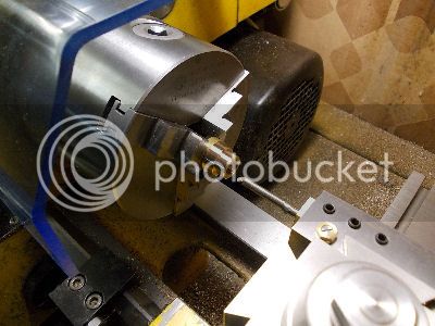
Before converting my lathe to it's milling configuration I made the two sacrificial bolts and finished the turning of the Exhaust Nipples. To do this I held them by their threads using a suitable hex nut as shown in the pic below.
CYACU18FinishingNippleInNut_zps0ba1343b.jpg


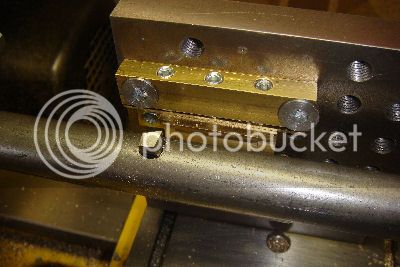
Making holes in the Cylinder Tube walls

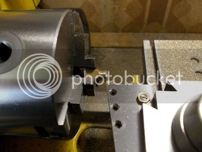
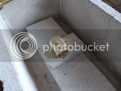
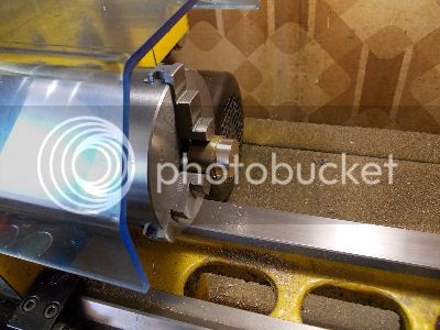
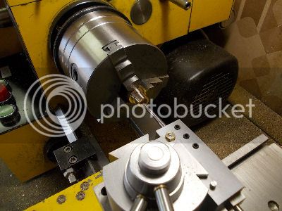
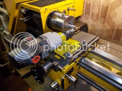
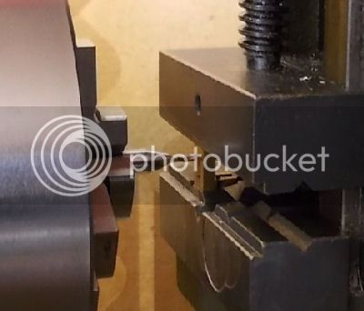
Here you see the shallow hole for the sacrificial bolt being tapped.
CYACU19TappingHoleInCylWall_zpsa753bad4.jpg


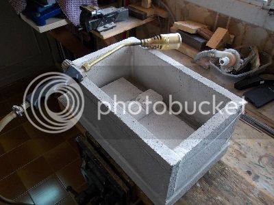
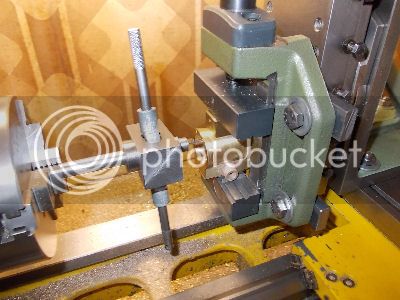
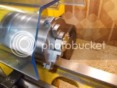
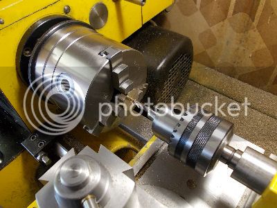
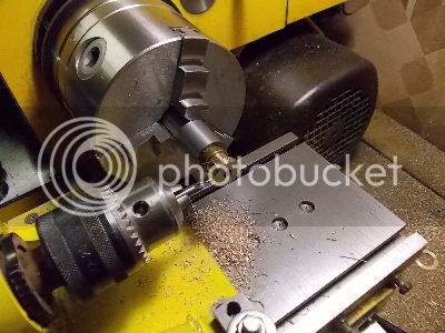
The next pic shows a Cylinder Tube being set up at an angle of 70 degrees from the lathe axis, in preparation for drilling the steam hole through the cylinder wall.
CYACU20CylSetUp20deg_zps806ea4d2.jpg


The next three pics show the milling of a small flat, the spot drilling and the final drilling of the steam hole.
CYACU21CylYZeroSet_zps1a5d93a1.jpg

CYACU22CylMillFlat_zps0d131554.jpg

CYACU23CylDrllSteamHole_zps04f6d5fa.jpg


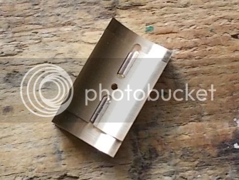
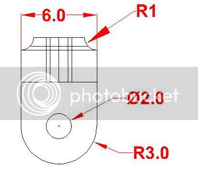
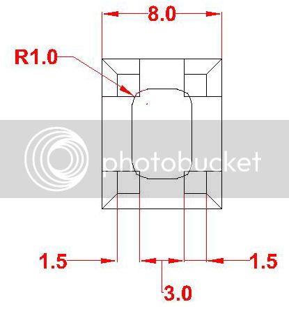
Making holes in the Cylinder Faces

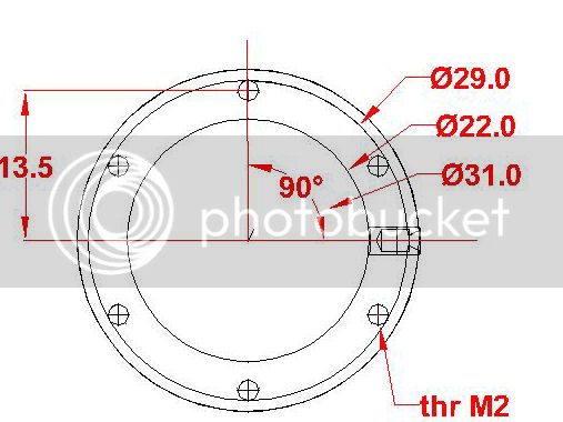
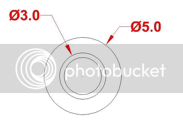
The Cylinder Faces have a 2mm hole at the center of the inner arc and two 3mm width steam channels to connect the steam ports to the holes through the Cylinder Tube walls.
CYACU24FaceMillPassage_zpsa9f2177e.jpg

CYACU25FaceOnePassageDone_zps769d9370.jpg


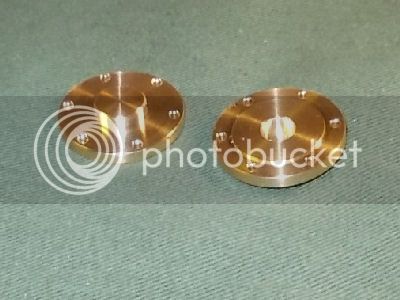
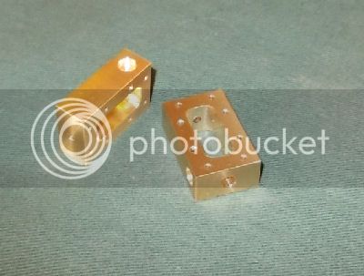
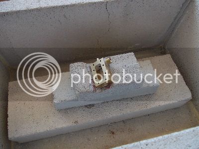
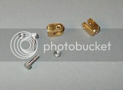
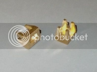
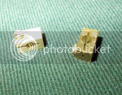
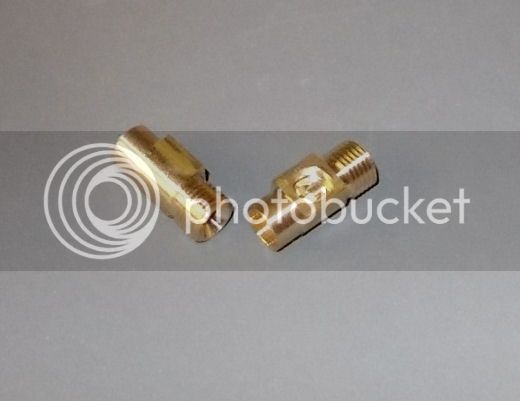
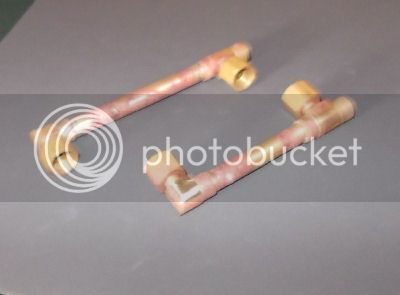
Sub-parts ready for soldering

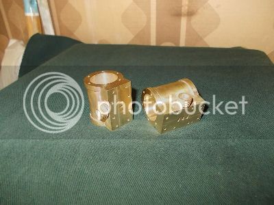
The pic below shows the three sub-psrts and scrificial bolt for each of the two Cylinder Units.
CYACU26AllSubpartsDone_zpsbf21c195.jpg


WHAT'S NEXT?
The next post will report of the work needed to complete the two Cylinder Units namely the silver soldering and then the final machining. As I mentioned before I'm always a bit nervous when there is silver soldering to be done, particularly when the parts being soldered are not small....
 
[SIZE=+2]THE CYLINDER ASSEMBLY - 3. Cylinder Unit - 2[/SIZE]

This post reports on the soldering and finish machining of the soldered Cylinder Units.
The drawings of all the parts of the Cylinder Units are attached to the first post on the Cylinder Assembly.

BUILD LOG

Silver Soldering

This first pic shows the "oven" and the propane torch with the biggest of the three nozzles. The oven is an open trough made of some sort of heat resistant building material (not asbestos!). From the same material I prepared a V perch for one Cylinder Unit.
CYACU27OvenAndTorch_zps98ab7e49.jpg


Below is a closeup showing two short pieces of silver solder in each of the two steam passages of the Cylinder Face.
CYACU28SolderInSlots_zps3f7c65b9.jpg


This is the solder which will flow into the curved gap between the Cylinder face and the wall of the Cylinder Tube. I also prepared a suitable "invitation" depression at both ends of the Cylinder Tube so that I could touch the silver solder rod at those points to fill the gap between the contact surfaces around the rims. The join between the Nipple and the Cylinder Face edge already presents an adequate "invitation" and so needs no special peparation.

Before uniting the three sub-parts I mixed the plux powder with a small amount of deionized water to make a smooth thick white paste and spread this liberally on all the contact surfaces. The Exhaust Nipple is held in place on the Cylinder face with the help of small bump made with a center punch on it's 6mm spigot. The Cylinder Face is held against the Cylinder Tube with the sacrificial screw. All the visible lines of contact between the parts were then liberally covered with flux paste. Here is a pic of the first victim ready for roasting.
CYACU29ReadyForRoasting_zps5aaf460a.jpg


I have no pics of the actual soldering process which, for me, is too tense and fast to admit such fun. In my very limited experience of silver soldering it is important to do the job quickly. This means having mentally rehersed the process first, it means applying abundant heat, it means not expecting the anti-oxidizing efficiency of the flux to last for more than a few seconds! For an experts advice on silver soldering I point you to Chris Heapy's Workshop Techniques:
http://www.astronomiainumbria.org/a...ca/easyweb.easynet.co.uk/_chrish/techindx.htm

As a matter of fact my first attempt failed. By the time I got around to touching the solder to the invitation on the second end, the flux was dead and the solder simply didn't want to know. The next pic shows the victim after pickling in battery acid and washing in abundant flowing water. I think you can see the unsoldered gap between the Cylinder Tube and the Cylinder face.
CYACU30RoastedAndPickledFailure_zps57ee760d.jpg


Making a new set of subparts took me a couple of days. The second time around the soldering of both Cylinder Units went well. I put more flux on the exposed surfaces all around the lines of contact, I used more heat right from the beginning, and I had the sequence of process steps much clearer in my mind.

The next pic shows one of these Cylinder Units after a preliminary cleaning with fine emery paper.
CYACU31AfterCleaning_zpsc1dd7345.jpg


At this point the two Cylinder Units were ready for finish machining.

Finish Machining


There were five separate setups, in the order listed below. Each setup was applied to both Cylinder Units before proceeding to the next setup.
  1. Face off the top end of the Cylinder.
  2. Face off the bottom end of the Cylinder and bore the Cylinder to its final diameter of 22mm.
  3. Mill the Port face, mill the steam ports, drill and tap M2 the 8 bolt holes.
  4. Make the 6 threaded holes in Cylinder's top end.
  5. Make the 6 threaded holes in Cylinder's bottom end.
Cylinder ends and bore

I'm sorry but I forgot to take snaps during the first two steps. I used the three jaw chuck and used my dial Indicator to check the absense of wobble.

Before starting I made a decision to allocate one of the units to be on the left (flywheel end) and the other to be on the right and made suitable distinguishing punch markings just below the two exhaust nipples. I was then careful for each Cylinder Unit to machine it's bore in the same setup used to face off it's the bottom end.

Valve Face

For the third and subsequent steps, the lathe is in it's milling configuration. Here the Cylinder Units are held vertically in the vice with emery paper protecting the cylinder ends. All positioning of the part for milling was done using the index dials of the cross slide and the vertical slide (being careful to feed always in the same direction when making the final approach to a new position). The zero setting of these dials was done by detecting the reference edges of the Cylinder Face (bottom and front) with the help of a length of 5mm stainless steel held in the 3-jaw chuck. This system probably gives me a certain systematic error (ie common to all positions) but does give a relatively high precision when moving from one position to the next.

To mill the Valve Face, I used a 12mm end mill and made two vertical passes with an overlap of 0.5mm at the center.
CYACU32MillingValveFace_zps55cc206f.jpg


The next three pics show the milling of the ports and the result. The 2mm end mill I used has a depth limit of 4mm which was just enough but which wouldn't have been enough if I hadn't decided, for other reasons, to mill the hidden steam passages into the Cylinder Face and not the Cylinder Tube wall!
CYACU33MillingPorts_zpsf7bc604a.jpg

CYACU34ExhaustPortDone_zpsc281e315.jpg

CYACU35AllPortsDone_zps1c54bb67.jpg


The pic below shows a moment during the tapping of the eight holes for the bolts which will fix the Steam Chest and it's cover to the Cylinder Unit.
CYACU36TappingValveFace_zpsf2a94b00.jpg


Tapped holes in Cylinder Ends

For making the six tapped holes in each end of each Cylinder Unit, I again used the lathe's milling configuration. This time the Cylinder Units were mounted horizontally with the Valve Face at the bottom (protected and raised to clear the Exhaust Nipple) and with a small brass V block at the top.

The pics below show the setting up using a face plate to ensure that the Cylinder End was square to the lathe's spindle axis, and using the 5mm rod in the 3-jaw chuck to do the zero setting of the Y and z slide index dials with the Cylinder bore as the reference. I chose the center of the bore as the origin ie Y = Z = 0.
CYACU37SettingSquare_zps56650872.jpg

CYACU38ZeroSettingYandZ_zps95ae56c3.jpg


Once the setup was complete the positioning for each of the holes was done in the same way as for the Valve Face. The six holes lie equidistant around a circle of radius 13.5mm. The table below gives the values of Y and Z for each of the holes.
Y=-13.50 Z=0
Y=+13.50 Z-0
Y=-06,75 Z=-11.69
Y=+06,75 Z=-11.69
Y=-06,75 Z=+11.69
Y=+06,75 Z=+11.69

The next two pics show the spot drilling and the tapping of one of the holes.
CYACU39SpotDrilling_zps8c607c54.jpg

CYACU40TappingCylRim_zpsb0be62de.jpg


Finish Machined Cylinder Units

Here finally is a snap of the two finish machined Cylinder Units. To complete them the Valve faces and the bores must be lapped but I will do this later.
CYACU41MaciningDone_zps706a9a15.jpg


WHAT'S NEXT?

As I'm anxious to mount these Cylinder Units in position and check the alignment of the whole I have decided to do the Cylinder Flanges and the Piston gear next.
 
[SIZE=+2]THE CYLINDER ASSEMBLY - 4. Cylinder Covers[/SIZE]

This post reports on the making of the top and bottom Cylinder Covers which I will call Flanges in this post. The drawings of all the parts of the Cylinder Units are attached to the first post on the Cylinder Assembly.

Here are some extracts from the drawings showing the Plan and Front 2D views of the flanges.
CYAFL00TopPlan_zpsfbfd8351.jpg
CYAFL00TopFront_zps3e949ef3.jpg

CYAFL00BottomPlan_zps55fca422.jpg
CYAFL00BottomFront_zps4ed4f8fe.jpg


BUILD APPROACH


Three aspecta of the build approach are worth mentioning.
  1. I decided to make the 6 bolt holes around the rims of the flanges using my lathe's milling configuration in the same way as I had done for the corresponding tapped holes on the cylinders. To do this the flanges have to have enough spare material to be able to grip them in the machine vice. For this reason I started making each pair of flanges (top + bottom) from a single chuck of 32mm brass rod. In fact these two chucks were the leftovers from the chunks from which the cylinders were made. With this in mind, the steps for making the flanges were as given below.
    • Using the 3-jaw chuck, machine on one end of a chunk the rim and the cylinder interface of the top flange, including the 8mm recess for the Piston Nut.
    • Reverse the chunk in the chuck and machine the rim and the cylinder interface of the bottom flange, including the 5mm hole for the piston rod.
    • Same again for the other chunk for the second pair of flanges.
    • Convert to milling configuration and drill the set of 6 holes in both ends of both chunks.
    • Sperate the two flanges in each pair. In fact I used a hacksaw as I didn't fancy trying such a long parting operation on the lathe.
    • Convert back to lathe configuration for machining the other faces
  2. For the bottom flanges it is very important that the locating disk on the cylinder interface, the hole for the piston rod, the 10mm spigot which fits the 10mm hole in the Platform, and the M10x1 thread on this spigot all be perfectly concentric. Getting perfect concentricity for features on opposite sides of a turned part rquires a bit of care. I decided to machine the side with the 10mm spigot and it's thread with the flange mounted on a custom mandrel with a closely fitting 5mm spigot through the hole for the piston rod and a nice fat shoulder to keep the flange square up against the face of the locating disk.
  3. For both the top and the bottom flanges the position of the flange is determined not by the fixing bolts but by the fit of the 0.5mm thick locating disk which enters into the cylinder bore. For this reason I decided to give the bolt holes in the flanges a diameter of 2.25mm instead of the nominal 2mm shown on the drawings. (The situation is similar to fitting a new back plate onto a chuck; the bolt holes through the back plate should be oversize so that the bolts dont interfere with the positioning of the back plate; their job is simply to hold the chuck firmly onto the back plate.)
BUILD LOG

This first snap shows the two chunks each with two flanges of which the cylinder interface and the outer rim has been machined. The material between the two rims was left with a diameter slighly larger than that of the flanges.
CYAFL01FlangePairs_zps337e99af.jpg


The next pic shows one of the pairs mounted in the machine vice for drilling the 6 bolt holes. The Y and Z zero setting was done by detecting the horizontal and vertical edges of the locating disk of the flange. The technique for positioning the flange to get the 6 holes in the right place was described in the previous post.
CYAFL02DrillingBoltHoles_zpsb3ca669e.jpg


Here then are the two pairs with the cylinder interfaces and bolt holes for all four flanges. The pairs are now ready for separating into separate flanges. The groove around the girth of the chunks is there to help me keep the hacksaw straight.
CYAFL03FinishedPairs_zps5e76235d.jpg


The machining of the upper faces of the top flanges was done holding them by the rim in the 3-jaw chuck with the help of a custom spacing washer made from white PVC as shown in the pic below.
CYAFL04FinishingTopFlange_zps5a7a4fc2.jpg


Here is a snap of the two finished top flanges.
CYAFL05FinishedTopFlanges_zpsc32048e7.jpg


Finishing the bottom flanges was more complex. First the outer faces of both bottom flanges were faced off to the final overall height (10.5mm including the locating disk).
CYAFL06FacingOffBottomFlange_zps02b72ca1.jpg


Then, from a bit of scrap mild steel bar, I made the custom mandrel with a nice fat shoulder (20mm diameter), a 5mm spigot 9mm long and a M4 thread 5 mm long. This mandrel remained in the chuck until the machining of both bottom flanges was finished.
CYAFL07CustomMandrel_zps86d682cb.jpg


The next two snaps show respectively the machining and the threading of the outer face of one of the two bottom flanges mounted on this custom mandrel.
CYAFL08MachiningBottomFlange_zpsa2136a0b.jpg

CYAFL09ThreadingBottomFlange_zpsb4940ce0.jpg


Here then is a pic of the two finished bottom flanges.
CYAFL10FinishedBottomFlanges_zps7c18e0d9.jpg


At this point of course (thankful for having prepared all the bolts first!) I could not resist mounting the Cylinder Units and the Flanges onto the Platform to check the fits and to get a first glimpse of what my steam engine would look like. During this process I discovered that I had boobed the position of two of the twelve bolt holes in the Platform - these two holes were about 0.25mm away from their correct positions. I corrected this with about half an hours work with a small rat-tailed hand file. One day I may decide to make a new Platform and recover from this one a Platform for the single cylinder version of the engine design. Here is a pic of the engine after these assembly operations.
CYAFL11CUsAndFLsIntegrated_zpsc4232244.jpg


WHAT'S NEXT?

The next job is to lap the bores of the cylinders and then make the two sets of Piston gear.
 
Last edited:
[SIZE=+2]THE CYLINDER ASSEMBLY - 5. Lapping Bores and Making Piston Gear[/SIZE]

This post reports on lapping the Cylinder bores and making the Piston gear. The drawings of all the parts of the Cylinder Units are attached to the first post on the Cylinder Assembly.

LAPPING THE CYLINDER BORES

From experiments with a temporary brass piston about 15mm in length I determined that the two cylinder bores were not only almost perfectly parallel but also of the same size to within 0.02mm. I decided to make use a single lap for both.

The lap was turned from a bar of aluminium which started life with a diameter of 35mm bar but which had already been used to make a lap for a cylinder of somewhat larger bore diameter. This time I used one end of this bar to make a shorter lap a bit over twice the length of the cylinders.

The target diameter for the lap was 0.04 less than the diameter of the smaller bore. However before making the final cut I make eight equi-spaced horizontal grooves along the length using a metric threading tool mounted horizontally in a tool holder and moving the lathe carriage by hand. These scores had a final depth of about 0.5mm. To control their spacing around the diameter I used my usual technique for indexing angles of the spindle using the screw cutting gear train as shown in previous posts.

Once the lap was made I cleaned the lathe, removed the tailstock, and positioned the carriage as far to the right as possible. The "grinding paste" I used was a very liquid mix of parafin and very fine pomice powder sold for polishing both stone (like marble) and metals. I also kept a supply of parafin handy for keeping the lap moist with the help of an old toothbrush.
As I had anticipated, the actual lapping process was quite quick. I started turning the lap by hand until the cylinder being lapped moved easily over the entire length of the lap. At that point I put a glove on my right hand to hold the cylinder, applied plenty of parafin, positioned the cylinder in the middle of the lap and turned on the lathe (250rpm) for the final polishing, being careful to keep the entire length of cylinder on the lap until I had turned off the lathe motor. No problems. Here are some pictures.

Making the grooves down the length of the lap
CYAPG04MachiningPistonNut_zps51d276c4.jpg


The lap ready for use
CYAPG02LapReady_zps32313ad0.jpg


A cylinder bore after lapping
CYAPG03CylAfterLapping_zpsa282de0a.jpg


MAKING THE PISTON NUTS

Here is an extract from the drawings.
CYAPG00PistonNutFront_zps41b33a60.jpg


It is important that the threaded hole through the nut be perfectly square with the flat face which will press down onto the Piston. Simirlar precision for the rim and for the hex spigot on the other side are not required. For this reason I used the first setup in the 3-jaw chuck to face off the bottoms and drill and thread the holes of both nuts. Then the machining of the rims and the spigot on the upper sides was done using a threaded M3 mandrel which I already had in my draw of such goodies. Here are some pictures.

Machining the upper face to form the spigot.
CYAPG04MachiningPistonNut_zps51d276c4.jpg


Filing the hexagon onto the spigot.
CYAPG05FilingPistonNutHex_zps2b798ead.jpg


The finished Piston Nuts.
CYAPG06FinishedPistonNuts_zpsd1b39982.jpg


MAKING THE PISTONS

Here are two extracts from the drawings.
CYAPG00PistonPlan_zps64d6726b.jpg

CYAPG00PistonFront_zps9b9d1fd8.jpg


Care is rquired when making the Pistons both because perfect concentricity and squareness is required for almost all its surfaces and becuase the Piston cannot be held by the external diameter once this has been turned to it's final diameter. I mulled over the best approach and finally decided the following sequence.
  1. Setup 1
    • Grip a suitable chunk of brass rod in the 3-jaw chuck with at least 20mm protruding 9ie enough for both Pistons. Turn the outer diameter to 22.5mm (i.e. about 0.5mm oversize with respect to the Cylinder bores) for a length of 20mm.
    • Drill and ream a 3mm hole down the center for a depth of 20mm
    • Face off the end and then cut or part off a slice of length a bit over 8mm.
    • Face off again and then cut or part off a similar slice for the second Piston.
  2. Setup 2
    • Mount one of these Pistons in the 3-jaw chuck using a spacer between it and the chuck face to ensure that the turned face is parallel to the chuck face.
    • Face off to reach the final Piston height of 8mm
    • Bore the recess for the Piston Nut
  3. Setup 3
    • Same again for the other Piston
  4. Setup 4
    • Use the 3-jaw chuck to make a custom mandrel with a fat shoulder and a partially threaded 3mm spigot like that on the upper extremity of the Piston Rod. The shoulder should be at least 36mm from the chuck jaws to allow the Piston to be tried down the full length of the cylinder. Do not remove this mandrel from the chuck until both pistons are finished.
    • Mount a Piston on the mandrel and finish machine its outer diameter to be a close sliding fit in the bore of one of the Cylinders.
    • Same again for the other Piston with the bore of the other Cylinder.
Here are some pics showing the application of this approach.

Machining the bottom face and the hole for the Piston Rod.
CYAPG07PistonBottomFace_zps1f73d42d.jpg


Plunging a 6mm end mill to start the recess.
CYAPG08PistonTopFacePlunging_zpsc809e349.jpg


Boring the recess to final size.
CYAPG10CustomMandrel_zps2e358908.jpg


The custom mandrel for turning the outer diameter.
CYAPG10CustomMandrel_zps2e358908.jpg


The finished Pistons.
CYAPG11FinishedPistons_zpsd2cbd969.jpg


MAKING THE PISTON RODS

Here are some extracts from the drawings.
CYAPG00PistonRodPlan_zps54e10787.jpg

CYAPG00PistonRodFront_zps354bf550.jpg


The key issue for making the Piston Rods is that one wants to use precision ground 5mm stainless steel rod but this makes it more difficult to ensure perfect concentricity of the threaded spigots at the end with the rod itself. The answer is to use the 4jaw chuck, a dial indicator and sufficient patience to mount the rod perfectly concentric with the lathe axis. Once this is done the amchining is simple. This process must be repeated for each end of each rod.

Here is a pic of a rod being setup in the 4-jaw chuck.
CYAPG17CenteringPistonRod_zpsaeaf8dbc.jpg


MAKING THE PISTON ROD GLANDS

Here are some extracts from the drawings.
CYAPG00GlandPlan_zpscf8150aa.jpg

CYAPG00GlandFront_zps5bd6a626.jpg


As can be seen, I decided a change with respect to the design shown in the original drawings because I have realized that it would be practically impossible to get a spanner anywhere near these glands let alone use it to adjust them. So instead of the glands having a hexagonal section they will be round (diameter 15mm) with ten 2mm holes equispaced along radii in the horizontal plane. This will allow the glands to be adjusted by inserting a 2mm lever into a hole. The shank of an old 2mm drill will make a good lever.

The hole for the piston rod and the M10x1 internal thread must be perfectly concentric and so will be machined in the same setup.

Here are some snaps of the build.
Boring the hole for the M10x1 thread.
CYAPG12BoringGland_zps4b46e025.jpg


Machine threading.
CYAPG13ThreadingGland_zps7a3ba172.jpg


Setup for drilling the ten radial holes using my electric drill fixed to the cross slide and indexing the angle of the lathe spindle with the gear train.
CYAPG14SetupForDrillingRose_zps00ce2212.jpg


Spot drilling for one of the radial holes. The spot drilling was of course followed by drilling to a depth of 4mm with a normal 2mm drill.
CYAPG15SpotDrillingRose_zpsf0755a0c.jpg


Here are the finished glands.
CYAPG16FinishedGlands_zps9498a036.jpg


TRIAL ASSEMBLY

Now having all the pieces I could try assembling the piston gear and integrating them with the rest of the engine. The first step was to mount the Piston gear with the cylinders and the bottom flanges onto the Platform and check the fits and alignments. I then added the Piston Slide and their suppports. The snap below shows the result at this stage.
CYAPG18CylsAndSlides_zps92d3af06.jpg


The fits seemed ok to me - i.e. a bit tight but without spots whch were tighter than others. I proceeded to mount this group on the top of the eight pillars and then connect the Small Ends of the Connecting Rods to the Piston Slides by inserting the pivot bolts. Here is a pic of the result.
CYAPG19Integrated_zps6a4485f4.jpg


Again the fits seemed ok and so I consider this phase satisfactorily concluded.

WHAT'S NEXT?

There is still quite a bit of work to do to finish the engine. The Steam Chests and Valve gear have to be made as do the Input and Exhaust Piping Assemblies. The engine also needs a solid and not too narrow wooden base. Then all parts need a bit of finishing. I love the interplay of natural metal colours and so am inclined not to paint anything.

Next on my plate is to make the two Steam Chest Units and their Covers. This means more silver soldering...
 
Last edited:
[SIZE=+2]THE CYLINDER ASSEMBLY - 6. Steam Chest Units and Covers[/SIZE]

This post reports on making the two Steam Chests and their covers. The drawings of all the parts of the Cylinder Assembly are attached to the first post on the Cylinder Assembly.

STEAM CHEST UNIT

Here are some extracts from the drawings.


CYASC00ChestPlan_zps196d3b5b.jpg
CYASC00ChestTop_zpsdd2d465d.jpg


Build Approach

The Steam Chest Unit is composed of three brass sub-parts silver soldered together. These parts are the Steam Chest itself, the Inlet Nipple and the Valve Rod Guide. While making the latter two are straight foreward turning tasks, the Steam Chest is quite a complex shape. Clearly most of the work would be done in the milling configuration - however the M8x1 internal thread for the Valve Rod Gland would have to be screw cut in the normal configuration with the work in the 4-jaw chuck.


I decided to use more of the 25mm diameter brass rod I had already acquired to make the Cylinder Face. The Build Plan for the Steam Chests was therefore clear.
  • Use the 3-jaw chuck to face off two bits of this bar to have a finished length of exactly 38mm.
  • Convert the lathe to its milling configuration with the machine vice oriented to close vertically.
  • Reduce these round bars to rectangular blocks with the required 22m x 12mm section by flycutting the four sides after careful setting up to ensure squareness.
  • For each Steam Chest in turn:
    • Mill the central cavity 10mm x 24mm) using first an 8mm end mill and then a 5mm end mill on the four corners.
    • Drill the eight 2mm bolt holes using the X (cross slide) and Z (vertical slide) index dials to position the work precisely for each hole.
    • Drill the 6mm x 3 hole at the top of one side for the boss of the Inlet Nipple.
    • Position the work at an appropriate angle and then drilling the 3mm hole from the above hole into the central cavity.
    • Drill the 5mm hole through the top for the Valve Rod Guide
    • Drill a 3mm hole through the bottom along the axis of the Valve Rod. Later, this hole would hold a custom jig to help center the work in the 4-jaw chuck for doing the M10x1 screw cutting.
      [/;ist]
    • Convert the lathe back to normal configuration.
    • Make a custom jig with an M3 spigot to go through the hole for the Gland and a boss of diameter 10mm to facilitate use of a Dial Indicator to center the Steam Chest in the 4-jaw chuck.
    • For each Steam Chest in turn:
      • With the custom jig in the 3mm hole, center the work in the 4-jaw chuck.
      • Drill and bore the hole to a diameter of 7mm for a depth of 4.5mm.
      • Screw cut the hole M8x1
    Build Log

    These three photos show the process of fly cutting the four sides of one of the 25mm bars to produce a block with a section of 22mm x 12mm. The second photo shows the use of a faec plate to ensure that the axis of the bar is perpendicular to the lathe's splindle axis. To produce flat surfaces, I prefer flycutting to milling with an endmill for two reasons: firstly I get a much better surface finish and secondly I can sharpen the flycutter toolbit but I cant sharpen endmills!

    CYASC01MakingBlocks1_zps3ae5df8d.jpg

    CYASC02MakingBlocks2_zps59b80e2d.jpg

    CYASC03MakingBlocks3_zps90cded8c.jpg


    Here are the finished blocks; sorry the photo is rather blurred.

    CYASC04BlocksReady_zpsd5eb259c.jpg


    The following pics show milling the central cavity and drilling the six bolt holes.

    CYASC05MillingInside_zps3f252734.jpg

    CYASC06DrillingBoltHoles_zpsaaf00128.jpg


    Here are the two Steam Chests at this stage.
    CYASC07BoltHolesFinished_zpse04236f4.jpg


    And here they are with the lateral holes for the Valve Rod Guide, The Inlet Nipple and, at the bottom, the custom jig.
    CYASC09LateralHolesDone_zps9957a522.jpg


    The next three photos show the custom jig itself, the jig being used with the Dial Indicator to center a Steam Chest in the four jaw for crew cutting the thread for the Valve Rod Gland, and the finished Steam Chests ready for soldering.
    CYASC10JigForCentering_zps025c5d6f.jpg

    CYASC11CenteringIn4jawForThreading_zps00928cca.jpg

    CYASC12ReadyForSoldering_zps71d2b46c.jpg


    The following rather blurred pic shows the two Valve Rod Guides ready for soldering. I didn't snap the Inlet Nipples because they're identical to the Exhaust Nipples soldered to the Cylinder Units.
    CYASC13RodGuides_zpsdd39250f.jpg


    Here you see one of the Steam Chests lying in the "oven" about to be silver soldered. The solder for the Valve Rod Guide was applied from insode the cavity to avoid messing the visible outside surfaces. The soldering of both Steam Chests went off without a hitch.
    CYASC14SetupForSoldering_zps8b67e3c9.jpg


    Here are two photos showing the Steam Chests after pickling and after a clean up with fine emery cloth.
    CYASC16AfterCleaning_zps4b2d396b.jpg

    CYASC15AfterPickle_zpsed4bb6e3.jpg


    STEAM CHEST COVERS

    Here are some extracts from the drawings.
    CYASC00CoverTop_zps725c495d.jpg
    CYASC00CoverEdge_zpse617a996.jpg


    Build Approach

    I decided to fabricate thee Covers dirsctly from 3mm brass plate. The machining of the edges and the recess on the ouetr face as well as the drilling of the eight bolt holes would all be done usibg the milling configuration of my lathe.

    Build Log

    After rough cutting two rectangles of brass plate with about 1mm of excess on both width and length, for each I first machined the four edges to make two 22mm x 36mm rectangles. To ensure squareness of the angles, before tightening the jaws of the machine vice, I gently press an already machined edge (after deburring!) up against the shank of a 2.5mm drill held reversed in the 3-jaw chuck.

    Then for each Cover in turn I mounted it in the machine vice with its faces normal to the lathe's spindle axis for drilling the bolt holes and milling the shallow decorative recess in the outer face, as shown in the following two pics.
    CYASC18DrillingBoltHolesInCover_zpsadf85ea8.jpg

    CYASC19MilingCoverRecess_zps6969e46e.jpg


    With the machining finished I then gave the facial and lateral surfaces a quick polish with fine emery paper. Here then is a snap of the finished Steam Chest Covers.
    CYASC20FinishedCovers_zps60df097e.jpg


    WHAT'S NEXT?

    The next course on my plate is to make two sets of Valve Gear namely the Slide Valve, the Valve Rod, the Slide Valve Pusher and it's Fixing Screw.
 
[SIZE=+2]THE CYLINDER ASSEMBLY - 7. Valve Gear[/SIZE]


This post reports on making the two sets of Valve Gear. Each set is composed of:
  • Valve Rod,
  • Valve Rod Link,
  • Valve Rod Gland,
  • Slide Valve,
  • Valve Pusher and it's Fixing Screw.
The drawings of all the parts of the Cylinder Assembly are attached to the first post on the Cylinder Assembly.

VALVE ROD

The Valve Rods are made of stainless steel. I decided to make them from precision ground 3mm rod. The hole down the axis with a lateral vent hole at 11mm from the top is to avoid back pressure when the rod moves in the blind hole of the Valve Rod Guide at the top of the Steam Chest. Here is an extract from the drawings.

VR00Plan_zps8868a923.jpg


I used the 3-jaw chuck to hold the rods both for drilling the hole down the axis and making the M2 thread at the other end. Drilling a fine hole in stainles steel requires a good quality drill and a bit of care and a bit of time. I drilled the lateral vent by punching a center pop and then using the drill press with the rod held in a small machine vice. I could have used the lathe but the vertical configuration of the drill press allows me to see better what I'm doing.
Here is a pic of the finished valve rods.

VR01Finished_zps322e18c8.jpg


VALVE ROD LINKS

The Valve Rod Links are part of the articulated joint between the Valve Rod and the Eccentric Rod. A 2mm bolt and nut joins each Valve Rod Link to the corresponding Eccentric Link on the end of it's Eccentric Rod. The Valve Rod Links themselves are made from brass. Here are two extracts from the drawings.

LK00Front_zps85c4c3c7.jpg

LK00Edge_zps264e0b0f.jpg


The links were made using the milling configuration of the lathe with the exception of the rounded collars which were turned holding the links on a short M2 Mandrel. Sorry I have no pics of the build process; here is a shot of the two finished Eccentric Links and the two mild steel M2 bolts and nuts which join them to the Eccentric Links.

LK01Finished_zpscae3f61d.jpg


VALVE ROD GLAND

These glands prevent the live steam from hissing out of the Steam Chest through the gap around the rod. I changed the design a bit with respect to the original drawings by introducing a hexagon section at the end to facilitate adjustment of the gland.

Here are some extracts from the new drawings.

GL00TopAndFront_zpsa753dca3.jpg


The glands were made from 10mm phosphor bronze rod. For a gland it is important that the hole for the valve rod and the thread be perfectly concentric - they must therefore be made in the same setup. I then made the hexagon by holding the gland in a threaded hexagon nut (which was itself held in the 3-jaw chuck) and using my file guide and the lathe gear train for indexing the angular position for each of the six flats. Here is a photo.

GL01FilingHex_zps18d6949d.jpg


SLIDE VALVE

Inspite of their finicky size the slide valves have a fairly complex shape to be produced with my lathe in it's milling configuration. With respect to the original drawing there is a small change - the depth of the vertical (3mm) slot is reduced from 6mm to 5mm. I did this because 5mm is sufficisnt to clear the Valve Rod and the 3mm end mill I have has a depth limit of 5mm!

Here are two extracts from the new drawings.

SV00Top_zps5004ac0d.jpg

SV00Plan_zps0e89cbef.jpg


First I made two rectangular brass blocks by milling away the excess from two bits of scrap brass.

SV01Blocks_zps50e66de8.jpg


Then I milled the bevels to produce the sloping sides. The angle of the slope can be derived from the drawings - it is arc tan(1/6). To set the block at the appropriate angle in the machine vice I used a carpenters angle guide as shown in the following snap.

SV02SettingUpForBevel_zpsa0acbb07.jpg


The next step was to mill the crossed slots. The block was mounted on its side in the machine vice - first I made the 5mm slot (moving the cross slide)and then the 3mm slot using the vertical slide.

Doing the job
SV03MillingSlots_zps429455da.jpg


Result
SV04SlotsDone_zpsbaf30cd2.jpg


The final step was to mill the recess which form the bridge between a cylinder port and the exhaust port.

SV05MillingBridge_zpsefc402ab.jpg


Here are the two finished Slide Valves.

SV06Finished_zps92c5c950.jpg


VALVE PUSHER AND IT'S FIXING SCREW

Other finicky customers! For them as well a minor design change: the pusher has been lengthened by 0.3mm so that the head of the Fixing Screw seats fully onto the 3mm recess on the top of the Valve Pusher.

Here are some extracts from the drawings.

PU00TopAndFront_zps5a2239cb.jpg

PU00ScrewPlan_zpsfa567233.jpg


I decided to make the two pushers at opposite ends of a bit of 5m x 5mm square rod. This was to facitate the last step of the machining which was to cut the slot down the middle so that the fixing screw would squeeze the two halves of the pusher and thereby grip onto the valve rod.
Since I didn't have any 5x5 rod I first produced it by milling away the excess from a bit of scrap brass. Then I drilled the 3mm holes from side to side. Rotating the bar 90 deg in the vice I then drilled the holes for the Fixing Screw - first at the diameter appropriate for a M2 tap and then, for half the depth (2.5mm) at a diameter of 2mm. At this point I could tap the bottom halves with an M2 tap held in my usual tapping guide.

This snap shows the bar at this stage of the game.

PU01MillingDone_zps1165cde2.jpg


At this point I converted the lathe back to it's normal configuration, mounted the 4-jaw chuck and used my Dial Indicator to center the bar in the chuck.

PU02CenteringForCut_zps3d4fc43d.jpg


Then, with the chuck oriented with the 3mm hole horizontal, I used my QCTP mounted manual slitting saw to cut the slot (slit?)

PU03CuttingSlot_zpsbc4c9510.jpg


Once the two slots were cut, I separated the two Pushers and faced of the cut ends again holding the work in the 4-jaw chuck.
The two Fixing Screws were turned from 3mm brass rod stock. The slits in the heads were made with the Slitting Guide shown above. Here is a pic of the two finished Valve Pushers with their Fixing Screws.

PU05WithFixingScrews_zps64ef9c4d.jpg


ASSEMBLED ENGINE WITH VALVE GEAR

As usual, at this point I could not resist the temptation to assemble all the existing parts of my engine. This time I even made the gaskets to seal the contact faces of both the Cylinder Covers and the Steam Chests and their Covers. I made the gaskets from a fairly heavy white paper. To make the holes I used the cover as a template with the paper pressed against it, first pricking each hole with a sharp pointed tool and then pushing a twist drill of the nominal hole diameter straight through with no twisting movement. This made technique produced fairly clean round holes of the right size. Here are pics of the gaskets.

CYACylCoverGaskets_zpsd07b0de2.jpg

CYASteamChestGaskets_zps0d906a72.jpg


Hear is the engine with the new Valve Gear and of course the Eccentrics and their Straps which have been patiently awaiting this moment for several months now.

CYAAssembledEngine_zps01c88c35.jpg


WHAT'S NEXT?

My next task is to make a wooden Base and the Inlet and Exhaust Manifolds which provide the two cylinders with common inlet and exhaust nipples. And then to see whether it will run on compressed air.
 
What a job....I can only dream about that. But a question....Why you build a steam engine??? Why you don't build a nice V8 with a blower??? If I see this , you can build anything!!!
Thanks for all that beautifull pictures , tekst & drawnings.

Greetings from Belgium

Barry
 
Hi Barry!
Thank you for your kind words.
I think I build steam engines because for me they have something noble and magic which stimulates my imagination in a way that no IC engine has ever done. I remember being sad about 60 years ago when I realized that those magnificent steam locomotives I so loved were being replaced by electric trains tapping energy from an overhead wire. Not to mention being thoroughly dismayed and upset when the electric ones were replaced by smelly diesel beasts.
As a young engineering student I did a two month stage in the maintenance shop of a major coal fuelled electric power station with enormous boilers furnishing superheated steam to a shining row of turbines each coupled to its dynamo. In that place too I would clamber about on narrow ladders and gangways soaking up the sights and odours and sounds that spoke gently of immense power kept under tight control.
So I got hooked as a kid and I'm still at it! I know it's not a very good reason but there it is...
 
[SIZE=+2]THE PIPING ASSEMBLIES[/SIZE]

This post reports on making the Inlet and Exhaust Manifolds which provide this two cylinder engine with a single input connector and a single exhaust connector.

The working drawing for these manifolds are attached to this post. Here are two extracts showing the manifolds.

PI00InletPiping2Model_zps4b44c619.jpg

PI00ExhaustPiping2Model_zps3dafb282.jpg


DESIGN CONSIDERATIONS

The design has been simplified with respect to the model images shown in the opening post of the thread. Each manifold is now composed of a Tee, an Elbow, a Pipe connecting the Tee to the Elbow, and two Male Collars each with a Nut to connect the Tee and the Elbow to one of the nipples on the engine cylinder assemblies. The connection interface of the nipple on the Tee is identical to the connection interface of the nipples on the engine cylinders. The four joints Male Collar - Elbow, Tube - Elbow, Tube - Tee and Male Collar - Tee are all silver soldered.

The only difference between the Inlet Manifold and the Outlet Manifold is the length of the Tube.

BUILD APPROACH


Two aspects of the build approach are worth mentioning.
  • I intended to fashion the rounded edges of the Elbow and Tee using my File Guide. This requires that the part to be filed be mounted in the lathe chuck with the axis of the curve along the lathe spindle axis. The curves concentric with the Tube presented no problem; they can be filed with the setup used to turn the bore which receive the Tube. However on the Elbow, the curve concentric with the Male Collar requires a special setup using a custom mandrel screwed temporarily to the Elbow along the axis of the Male Collar. Once the curve has been filed, then the hole to receive the Male Collar can be machined to its final size.
  • The Manifolds are rigid; they have little flexibility to tolerate poor alignment between the axes of their Male Collars and the axes of the mating nipples on the Cylinders. This implies an important requirement that the parts of the Manifolds must be firmly held in the right relative positions during the soldering process. To ensure this for each Manifold I made a custom jig consisting of a brass bar with two nipples having the same relative positions as those on the Cylinders. The position on the bar of one of the nipples of the jig coud be adjusted before tightening is fixing nut, and the correct distance between the nipples of the jig was ensured by fixing the jig itself to the engine using two short threaded sleeves each of which engaged the threads on both an engine nipple and a jig nipple. In this setup, the nut holding the adjustable nipple on the jig was tightened.
BUILD LOG

Male Collars and Nuts

Making the Male Collars and the Nuts is fairly straight foreward turning. To make the internal M10x1 threads of the nuts, I choose to turn them on the lathe without using the motor i.e. to turn the lathe spindle by hand. This ensures that a fully dimensioned thread reaches right the bottom of the nut; something a die cannot do. I use a bit of sticky tape of the rim of the chuck to indicate the exact angle at which to stop turning the spindle and the bottom of the thread.
Here is a rather dark pic of the turning of the 45deg taper on a Male Collar, followed by a snap of the finished Male Collars and Nuts.

PI01MakingCollarTaper_zps8847c633.jpg

PI02FinishedCollarsAndNuts_zpsa64ec771.jpg


Elbows and Tees

I decided to make the Elbows and Tees from 10x10 square brass stock of which I had a short but sufficient piece. This required using my 4-jaw chuck and going through the process of getting the bar to run true using the technique with the Dial Indicator and two small chuck keys. I'm getting better and quicker at doing this now and am beginning to appreciate that, when necessary, I can get a part to run more truely using the 4-jaw than it does with the 3-jaw self centerer.
The first step was to machine the Pipe interface end and file the curve concentric with the pipe for both Elbows and both Tees. Here is a pic of the setup for filing the curves, followed by a pic of the four parts at the end of this step.

PI03TeeFilingCurve_zps33b0e343.jpg


PI04TeesAndElbowsForMilling_zpsc03eb857.jpg


The lathe was then converted temporarily to it's Milling Configuration, and the Elbows were prepared to accept the Custom Mandrel by making a M4 thread along the Male Collar Axis for a depth of 6mm.

Here is a pic of the Custom Mandrel (which I already had from some previous exercise), followed by a pic of the curve concentric with the Collar being filed on one of the Elbows.

PI05MandrelForElbows_zps2797bda1.jpg

PI06ElbowFilingCurve_zpsa3c8a0b0.jpg


And here is a snap of the two Elbows after this filing.

PI07ElbowsAfterFiling_zps01743356.jpg


At this point, with the lathe once again in Milling Configuration, the holes for the Male Collars were finalised. Then back to Turning Configuration to machine the M10 nipples of the two Tees, again using the 4-jaw chuck. For the external M10 threads I used motor power. Here is a pic of the finished Tees.

PI08FinishedTees_zps13617d01.jpg


Soldering

Here is a picture of the Custom Jig for the Inlet Manifold.

PI09SolderingJig_zpsb4476660.jpg


This snap shows the Inlet Manifold fixed to the Jig lying in the oven ready for soldering. All contact surfaces, including the internal ones, were cleaned with fine emery paper and then covered with flux paste. Naturally I avoided allowing any flux to reach the Nuts and the position of the Jig ensures that molten flux will run down onto the Elbow or Tee and not up onto the Nut.

PI10ReadyForSoldering_zps2a079932.jpg


The soldering went off without problems. Here is a pic showing the two manifolds after a short pickle in battery acid and and a good wash in abundant water.

PI11AfterPickle_zps409b3005.jpg


I then cleaned the manifolds using fine emery paper and mounted them on the engine. The trouble taken to make the custom jigs seems to have been worth it, the Nuts of both Manifolds screw easily with no binding onto the mating nipples on the engine. This final snap shows a back view of the Engine with the mounted Manifolds.

PI12Mounted_zpscf302fdf.jpg


WHAT'S NEXT?

Apart from needing a wooden Base for stability, the engine is now complete and ready for testing on compressed air.

View attachment Piping2 Assemblies 1of1.pdf
 
What a great project and very well presented. Many thanks
Wulyum:D
 
Thank you Wulyum; glad you like it. I've enjoyed making it and am dying to see it running which could be in the next few days.
Bye the way, I couldn't find the customary introductory post about you in the Welcome section of the forum. Have you posted one?
 
[SIZE=+2]SEEING IT RUNNING[/SIZE]

This post reports on first test runs of the completed steam engine. It is now screwed to a simple base of varnished wood. Attached to this post are the last two working drawings which show the models of the integrated engines respectively with one cylinder and with two cylinders.
Here are four snaps of the finished engine.

Front
Front_zps22e773aa.jpg


Front Right
FrontRight_zpsa55bdc10.jpg


Back
Back_zps8451277d.jpg


Back Right
BackRight_zps3b72749d.jpg


FIRST TESTS

The testing was done with compressed air and was all over quite quickly. First I removed the Inlet and Exhaust Manifolds and made the engine run with only one cylinder connected to the compressed air line; the other cylinder was therefore a small load. In this way I checked the correct timing and functioning of the valve. Then the same again for the other cylinder. Then I remounted the Manifolds and was finally able to see and hear my engine running as recorded by the following rather clumsy video. Towards the end this video tries to demonstrate the self-starting property of the engine conferred by the 90 degree angle between the cranks.

http://s1061.photobucket.com/user/romartin1/media/VerticalEngine/EngineRunning_zps2a36bfeb.mp4.html

UPDATES TO DRAWINGS


I have updated all the drawings to reflect the engine as built. Rather than create new places for these updated drawings I preferred to replace the old versions in the posts to which they were attached. The list below indicates where to find these new versions of the drawings.
  • Base1 Assembly 10f1.pdf - Post #2 on Page #1
  • Base2 Assembly 10f1.pdf - Post #2 on Page #1
  • Vertical Structure1 Assembly 1of1.pdf - Post #4 on Page #1
  • Vertical Structure2 Assembly 1of1.pdf - Post #4 on Page #1
  • Shaft1 Assembly 1of2.pdf - Post #5 on Page #1
  • Shaft1 Assembly 2of2.pdf - Post #5 on Page #1
  • Shaft2 Assembly 1of1.pdf - Post #5 on Page #1
  • Cylinder Assembly 1of3.pdf - Post #16 on Page #2
  • Cylinder Assembly 2of3.pdf - Post #16 on Page #2
  • Cylinder Assembly 3of3.pdf - Post #16 on Page #2
  • Piping2 Assemblies 1of1.pdf - Post #53 on Page #6
  • Overall1 Assembly 1of1.pdf - This post
  • Overall2 Assembly 1of1.pdf - This post
CONCLUSION

Well that's it! I have enjoyed this experience of keeping a public log of the build as it progressed and would like to thank all those folk who have followed this trail and have provided me with much stimulus and encouragement.

View attachment Overall1 Assembly 1of1.pdf

View attachment Overall2 Assembly 1of1.pdf
 

Latest posts

Back
Top