Philjoe5
Well-Known Member
- Joined
- Jul 12, 2007
- Messages
- 1,727
- Reaction score
- 321
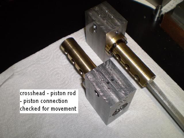
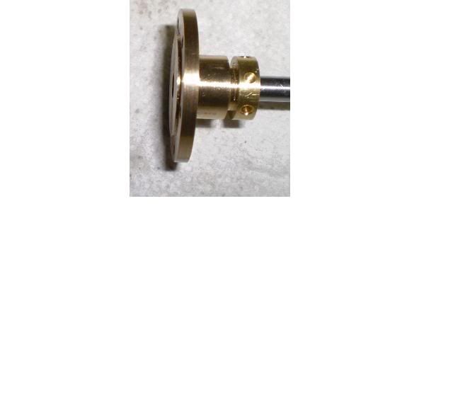
Ive built several versions of a single cylinder oscillating rotary valve steam engine to get my machining skills sharpened. Now Im building a two cylinder version of this engine. Im working off the set of plans for the one cylinder engine, making modifications as needed.
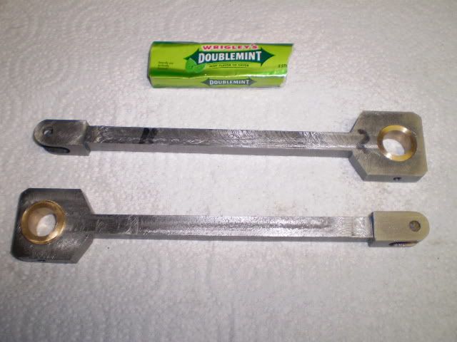
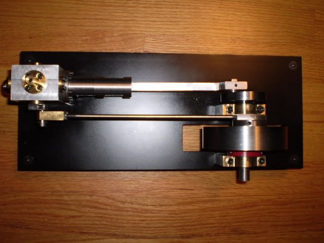
Heres a photo of one of the singles Ive built:
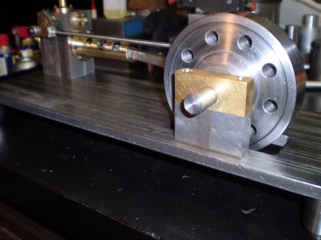
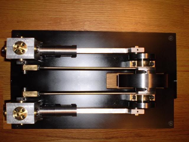
Through the magic of photo editing software Ive made a picture of the 2 cylinder engine Im building:
Basically Im going to take the cylinder con rod eccentric assemblies, duplicate them, and put them on the other side of the flywheel. The crank pins on the crankshaft will be offset by 90 degrees so the engine will self start.
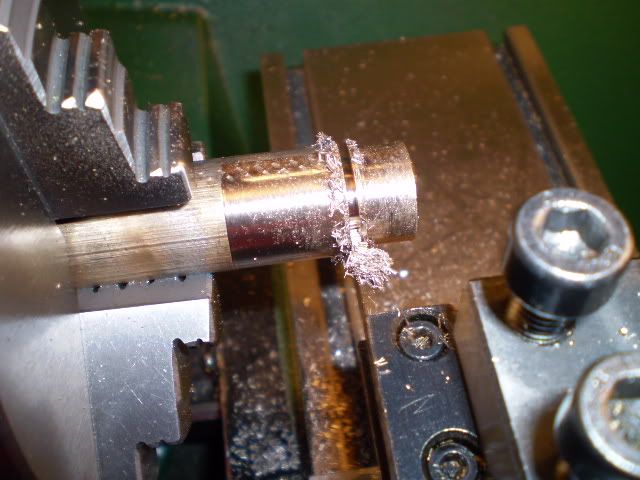
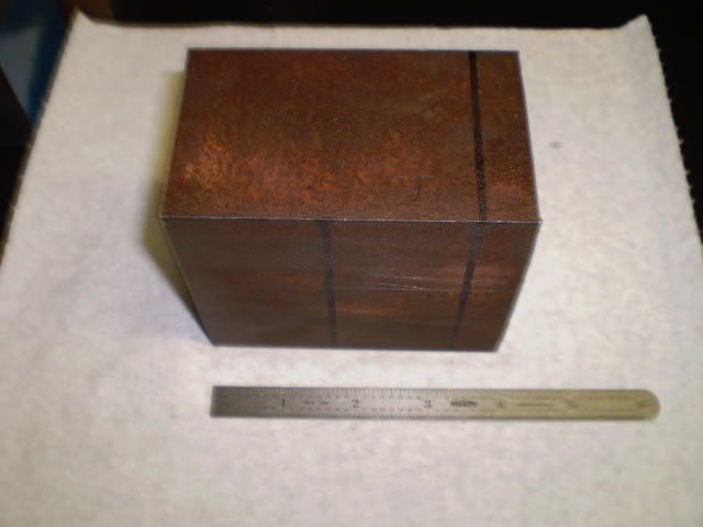
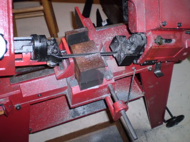
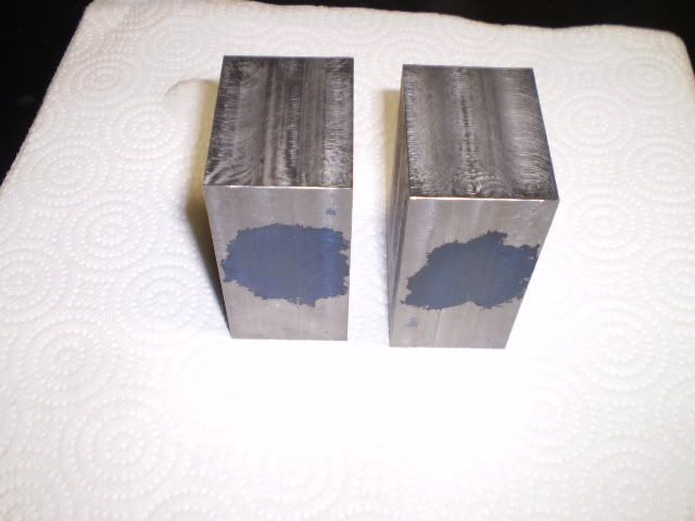
Now for my first progress report. All barstock engines start with a good lump of metal, in this case some 1144 free machining steel:
My trusty bandsaw is making 2 cylinder blocks here:
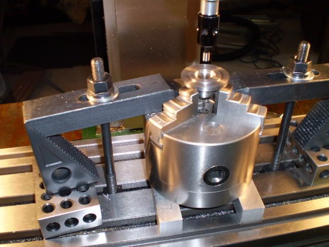
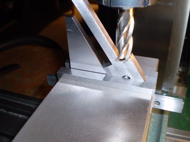
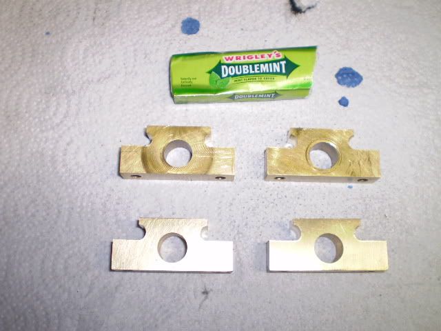
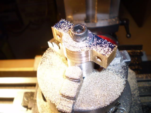
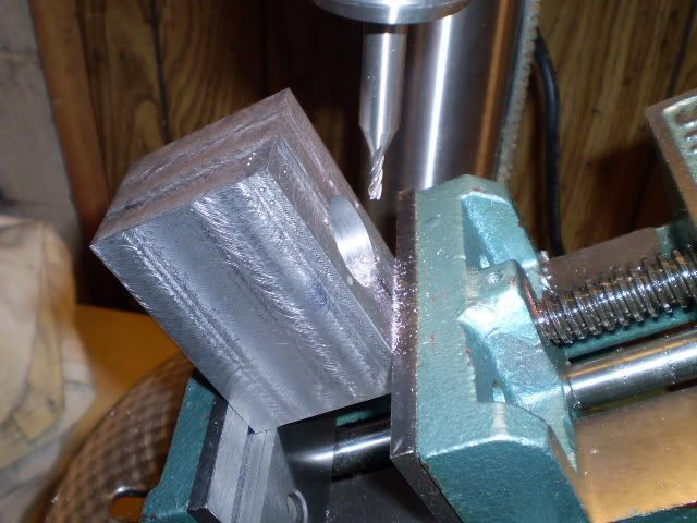
A little milling machine work and here are the blank cylinder blocks ready for some machining:
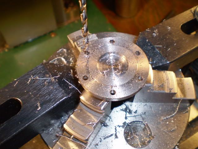
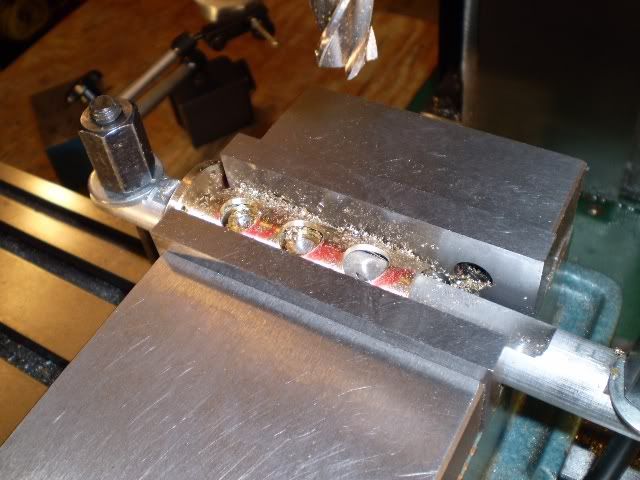
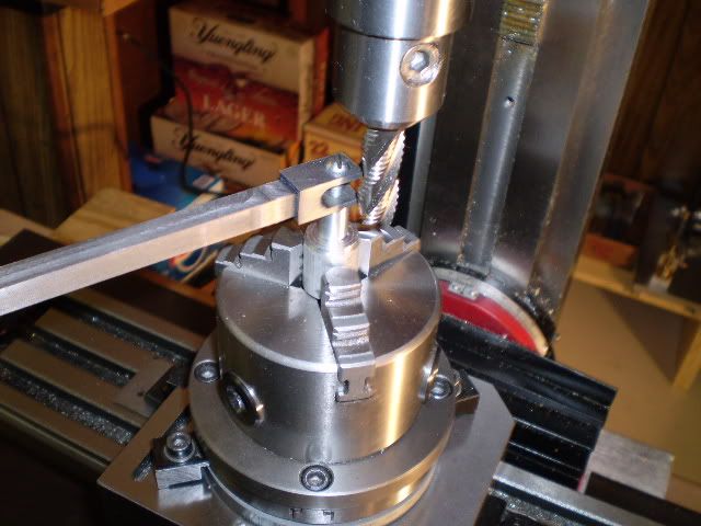
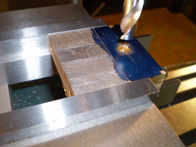
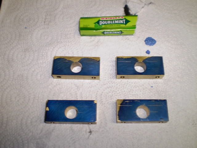
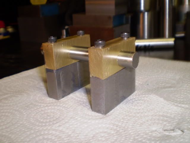
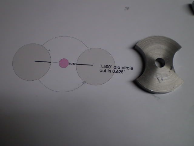
There are 2 passageways that are drilled at 30 degree angles from the cylinder bore to the valve port. I start these with an end mill to make a flat, then drill the passageway. This operation takes a light touch to keep the end mill or drill bit from wandering.
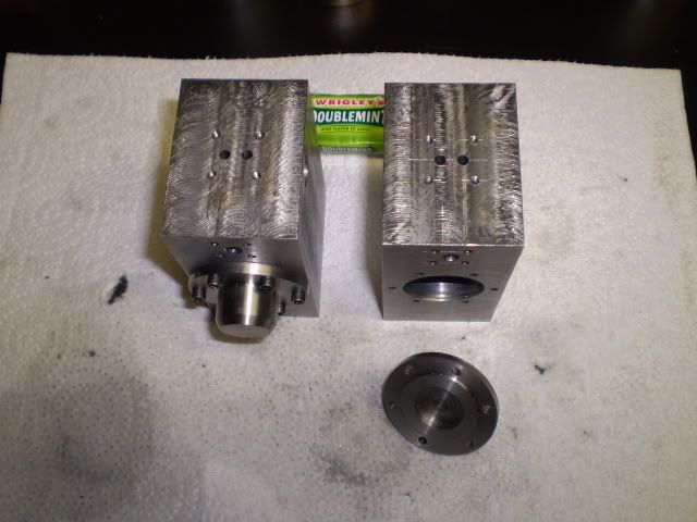
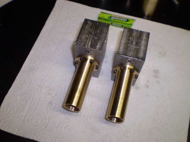
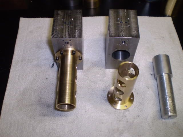
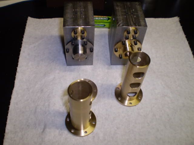
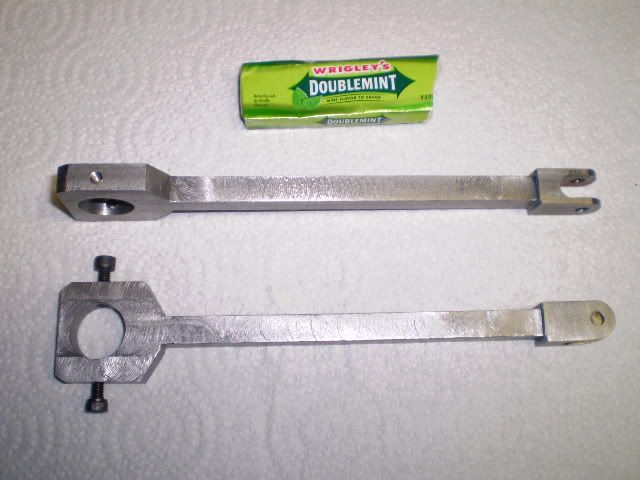
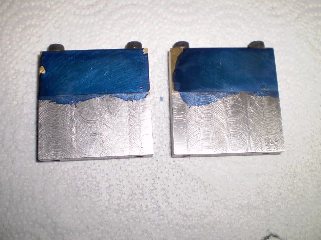
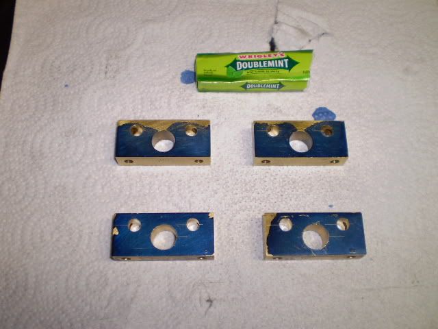
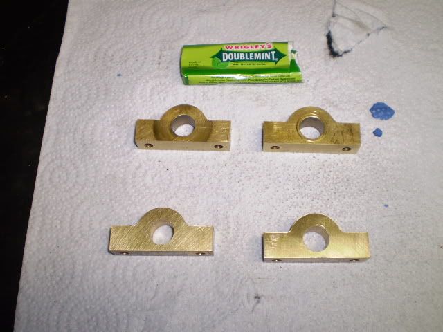
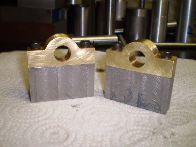
Several drilled holes and 56 tapped holes later, here are two cylinder blocks finished!
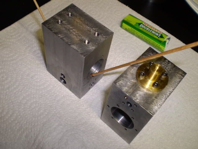
They are nearly identical. Using some cylinders from my parts box, Ive estimated theres about a 0.003 difference in bores between the 2 cylinders. Thats OK because the pistons will be machined to fit their individual bores.
Ill try to post regularly to keep you all informed of my progress. At some point Ill need some advice so if you can help jump in.
Cheers,
Phil
Heres a photo of one of the singles Ive built:
Through the magic of photo editing software Ive made a picture of the 2 cylinder engine Im building:
Basically Im going to take the cylinder con rod eccentric assemblies, duplicate them, and put them on the other side of the flywheel. The crank pins on the crankshaft will be offset by 90 degrees so the engine will self start.
Now for my first progress report. All barstock engines start with a good lump of metal, in this case some 1144 free machining steel:
My trusty bandsaw is making 2 cylinder blocks here:
A little milling machine work and here are the blank cylinder blocks ready for some machining:
There are 2 passageways that are drilled at 30 degree angles from the cylinder bore to the valve port. I start these with an end mill to make a flat, then drill the passageway. This operation takes a light touch to keep the end mill or drill bit from wandering.
Several drilled holes and 56 tapped holes later, here are two cylinder blocks finished!
They are nearly identical. Using some cylinders from my parts box, Ive estimated theres about a 0.003 difference in bores between the 2 cylinders. Thats OK because the pistons will be machined to fit their individual bores.
Ill try to post regularly to keep you all informed of my progress. At some point Ill need some advice so if you can help jump in.
Cheers,
Phil