
You are using an out of date browser. It may not display this or other websites correctly.
You should upgrade or use an alternative browser.
You should upgrade or use an alternative browser.
A two cylinder mill engine under construction
- Thread starter Philjoe5
- Start date


Help Support Home Model Engine Machinist Forum:
This site may earn a commission from merchant affiliate
links, including eBay, Amazon, and others.
Brass_Machine
Well-Known Member
- Joined
- Aug 28, 2007
- Messages
- 1,314
- Reaction score
- 7
Great idea for those caps Phil.
I should be at Cabin Fever. Don't know if I will be working a booth or not (for CNCzone)... But I should be there.
Eric
I should be at Cabin Fever. Don't know if I will be working a booth or not (for CNCzone)... But I should be there.
Eric
Philjoe5
Well-Known Member
- Joined
- Jul 12, 2007
- Messages
- 1,727
- Reaction score
- 321
The past week was spent making the crankshaft. My design has five major pieces a main shaft, two crank webs and two crank pins. The webs will be attached to the main shaft and pinned in place with 1/8 steel pins. Since the flywheel and eccentrics are captive between the webs, the pins will allow for web removal when I first assemble (and disassemble) the engine to get it running. Once I get the engine working I can loctite the webs to the shaft if necessary for semi-permanence.
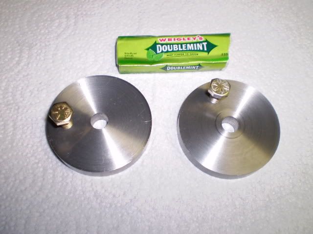
The crank webs are 3/8 thick steel disks that are center drilled/and reamed 0.375. A ¼ 28 NF hole is tapped at a distance of 0.688 from the center hole. A ¼-28 bolt attaches a sleeve to form the crank pin for attached the connecting rod. There is a small hub on the crank web thats 5/8 diameter and 0.030 thick. This prevents the full wall of the web from contacting the bearing blocks in the assembled engine, thereby reducing friction.
I faced the web disks on the lathe, made the hub, then center drilled/reamed the center hole. Then I clamped the lathe chuck to the mill table, centered the spindle over the web center hole. For this operation I use a piece of ½ drill rod in an end mill holder thats well secured in the chuck thats loosely clamped to the mill table. Then, the chuck is carefully clamped to the table and finally the table locks secured.
At this point, the set screw on the end mill holder is loosened, and the mill head is raised so that the drill rod clears the end mill holder completely. Now the mill head is lowered so that the drill rod enters the end mill holder. If there is no significant contact between the end mill holder and the drill rod, Im done. Otherwise I start over with clamping. Other more tedious methods used to center the spindle over the chuck using dial indicators or edge finders never disagree with this method by more than 0.002 so if I can work to that tolerance (like here) I use this method. Now the crank web is mounted in the chuck and the table is moved 0.688 and drilled/tapped with ¼-28 NF threads.
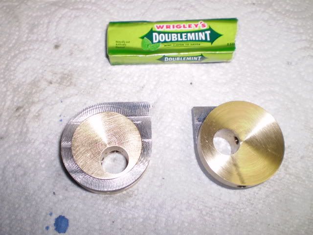
I was contemplating how to cut the arcs in the webs and keep everything aligned. I cant trust my eyes to align stuff so Im thinking fixture. I came up with this design.
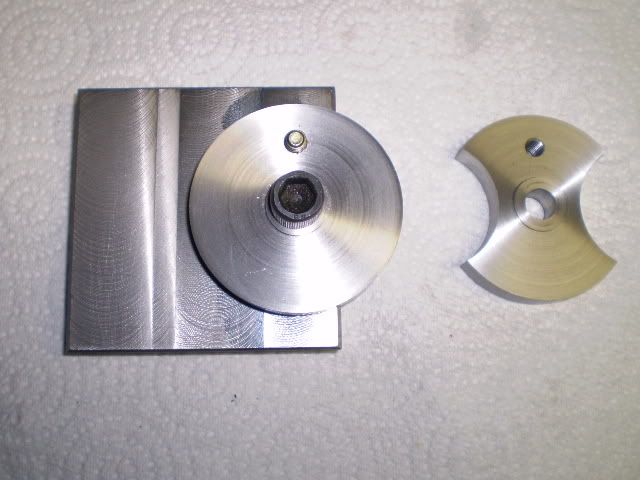
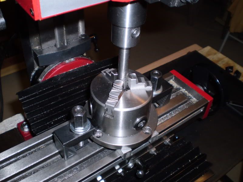
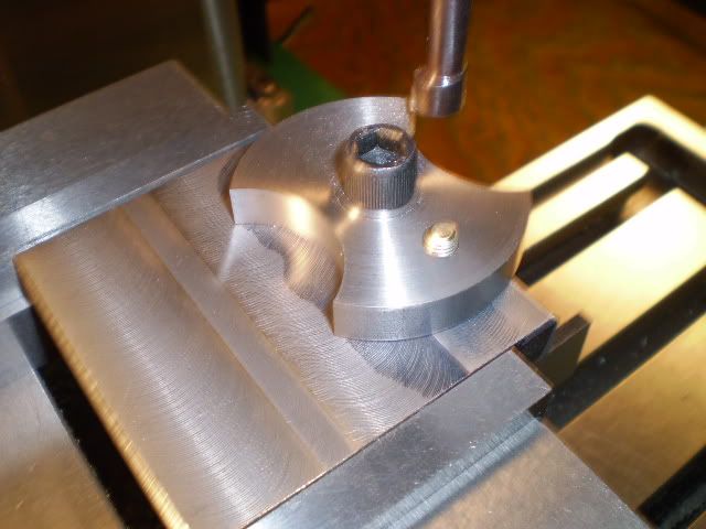
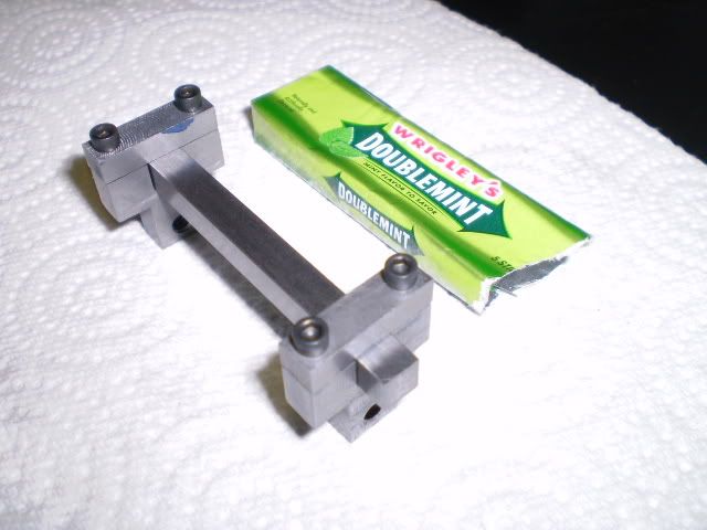
The center hole of the fixture is tapped 3/8-16 NC and the two ¼ locating holes are drilled. I bolted the web to the fixture, set the arc diameter on the boring head to 1.50 (a purely arbitrary setting that looked good to me). Then I adjusted the table x axis so the boring bar just kissed the edge of the workpiece. I found I could use 0.015 DOCs without making the machine or me nervous about this interrupted cut. I cut in a total of 0.625 (again arbitrary), swung the web around on the fixture and cut the other side. Here is a photo of the setup on the mill with the arc cut on one side:
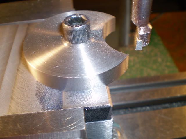
then the other:
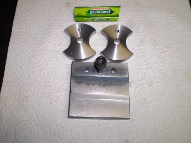
Both webs finished with the fixture used to make them
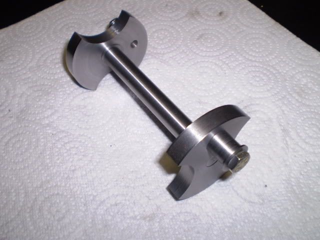
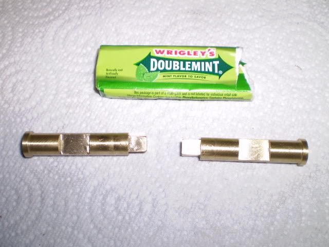
Then a piece of ½ drill rod was cut for the crankshaft. It was faced off to length, then turned down to a diameter of 0.375 on each end to fit the crank webs snugly, but not a press fit. I have heard (cant remember the source, one of the steam loco groups I think) that one of the most common failures of a joint that is secured by loctite is a fit that is too tight, such as a press fit. So I typically try for something between close and press fit and I havent had a failure yet. The overall length of the crankshaft was calculated and has to be pretty close to actual dimensions. I made it 0.020 longer than necessary to accommodate 2 cranks webs, 2 eccentrics and a flywheel and 2 bearing blocks. This photo shows the crank webs temporarily mounted on the ends
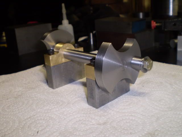
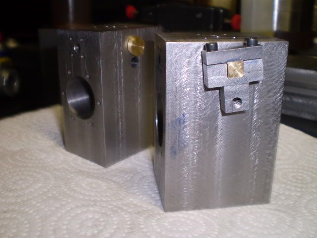
Here, Ive mounted the crankshaft on the bearing blocks
Im in the mood for some lathe work so Ill tackle the flywheel next.
Cheers,
Phil
The crank webs are 3/8 thick steel disks that are center drilled/and reamed 0.375. A ¼ 28 NF hole is tapped at a distance of 0.688 from the center hole. A ¼-28 bolt attaches a sleeve to form the crank pin for attached the connecting rod. There is a small hub on the crank web thats 5/8 diameter and 0.030 thick. This prevents the full wall of the web from contacting the bearing blocks in the assembled engine, thereby reducing friction.
I faced the web disks on the lathe, made the hub, then center drilled/reamed the center hole. Then I clamped the lathe chuck to the mill table, centered the spindle over the web center hole. For this operation I use a piece of ½ drill rod in an end mill holder thats well secured in the chuck thats loosely clamped to the mill table. Then, the chuck is carefully clamped to the table and finally the table locks secured.
At this point, the set screw on the end mill holder is loosened, and the mill head is raised so that the drill rod clears the end mill holder completely. Now the mill head is lowered so that the drill rod enters the end mill holder. If there is no significant contact between the end mill holder and the drill rod, Im done. Otherwise I start over with clamping. Other more tedious methods used to center the spindle over the chuck using dial indicators or edge finders never disagree with this method by more than 0.002 so if I can work to that tolerance (like here) I use this method. Now the crank web is mounted in the chuck and the table is moved 0.688 and drilled/tapped with ¼-28 NF threads.
I was contemplating how to cut the arcs in the webs and keep everything aligned. I cant trust my eyes to align stuff so Im thinking fixture. I came up with this design.
The center hole of the fixture is tapped 3/8-16 NC and the two ¼ locating holes are drilled. I bolted the web to the fixture, set the arc diameter on the boring head to 1.50 (a purely arbitrary setting that looked good to me). Then I adjusted the table x axis so the boring bar just kissed the edge of the workpiece. I found I could use 0.015 DOCs without making the machine or me nervous about this interrupted cut. I cut in a total of 0.625 (again arbitrary), swung the web around on the fixture and cut the other side. Here is a photo of the setup on the mill with the arc cut on one side:
then the other:
Both webs finished with the fixture used to make them
Then a piece of ½ drill rod was cut for the crankshaft. It was faced off to length, then turned down to a diameter of 0.375 on each end to fit the crank webs snugly, but not a press fit. I have heard (cant remember the source, one of the steam loco groups I think) that one of the most common failures of a joint that is secured by loctite is a fit that is too tight, such as a press fit. So I typically try for something between close and press fit and I havent had a failure yet. The overall length of the crankshaft was calculated and has to be pretty close to actual dimensions. I made it 0.020 longer than necessary to accommodate 2 cranks webs, 2 eccentrics and a flywheel and 2 bearing blocks. This photo shows the crank webs temporarily mounted on the ends
Here, Ive mounted the crankshaft on the bearing blocks
Im in the mood for some lathe work so Ill tackle the flywheel next.
Cheers,
Phil
Philjoe5
Well-Known Member
- Joined
- Jul 12, 2007
- Messages
- 1,727
- Reaction score
- 321
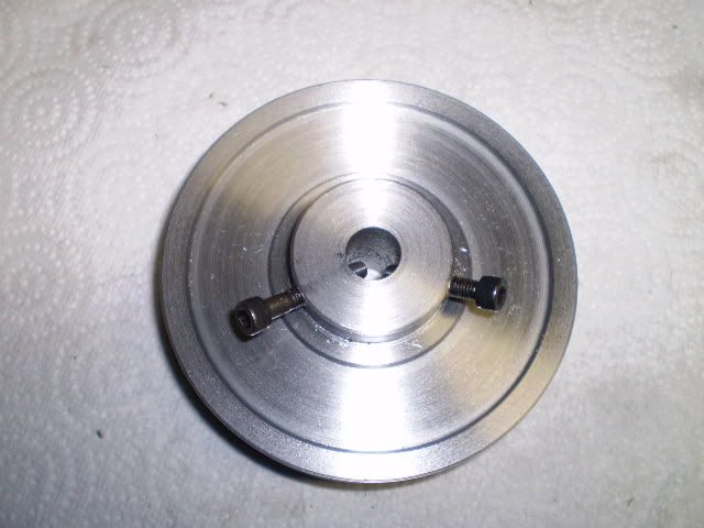
Since my last post Ive made a flywheel. Nothing fancy but functional. Plans call for a 6 cast iron wheel but Ill be using some barstock I have on hand. I have some 4 diameter hot rolled steel and Ill make a flywheel out of that. I cut a slice off my stock thats about 1.5 thick. Next, I faced it off on both sides, cut a recess on both sides reamed the center hole ½. I tapped two holes with 10-32 threads for set screws. I start these holes at a 30 degree angle from the vertical using a centercutting 1/8 end mill.
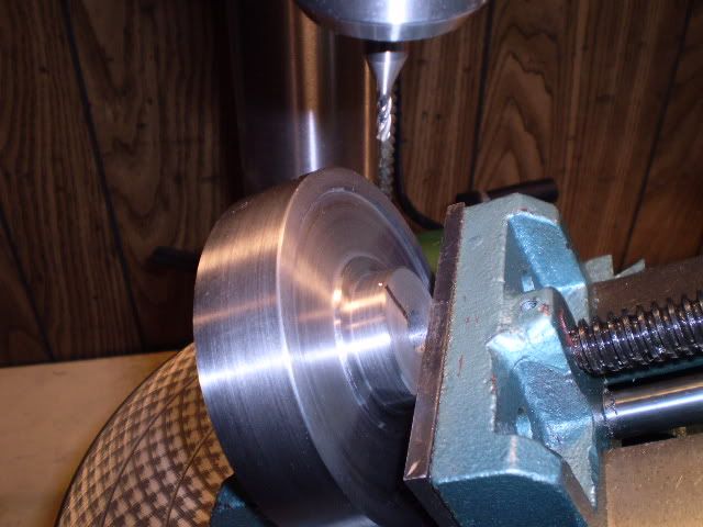
Heres the flywheel, hub side up with two cap screws in place (not the set screws Ill be using) to illustrate placement of the set screws.
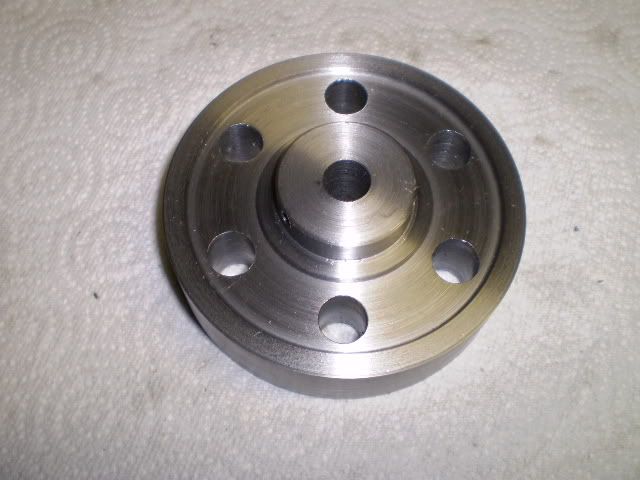
Now drill some ½ holes so the spinning flywheel looks interesting
Am I done? Not quite. A little paint does wonders:
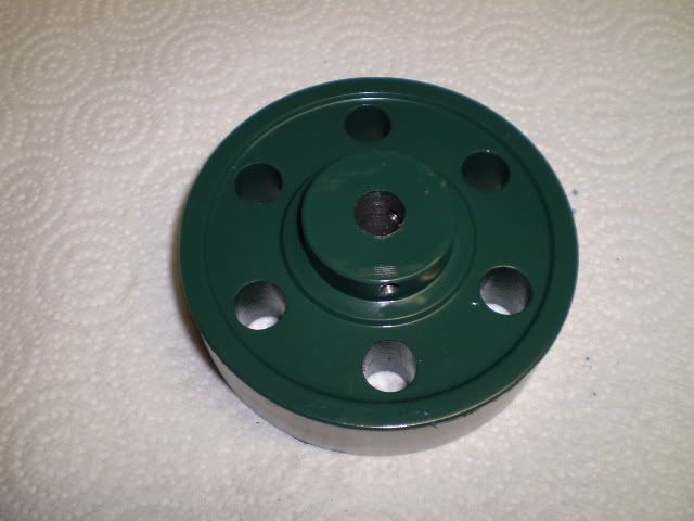
Ill call the flywheel finished. Now that Ive cut the crankshaft to length Ive pretty much determined the spacing of the two cylinder blocks. Now I can layout the cylinder blocks and the flywheel and bearing blocks on a wooden baseplate. With the cylinder blocks and bearing blocks mounted on a baseplate I can hook up the con rods to both cylinders (without any valve operation) and see how smooth movement is (or not!).
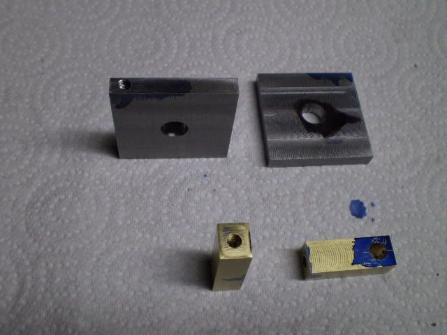
Next up for machining are the eccentric straps and the valve rod bearings. These are fairly small pieces so I found some stock in the recycle bin and sliced off some workpieces on the bandsaw. Next, I milled them to size. Then I drilled/tapped them and finally I reamed some pivot holes. These are going to serve as pivot points on the rotary table for rounding these parts.
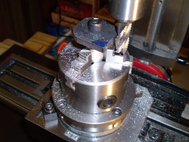
Rounding one of the eccentric straps
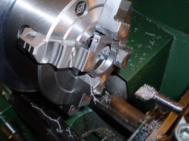
One of the eccentric straps being bored out
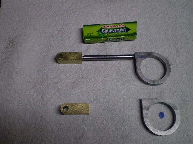
And the completed straps and valve rod bearings
Now Im off to visit my brother who just broke a bone in his foot falling off a ladder.
Cheers,
Phil
Heres the flywheel, hub side up with two cap screws in place (not the set screws Ill be using) to illustrate placement of the set screws.
Now drill some ½ holes so the spinning flywheel looks interesting
Am I done? Not quite. A little paint does wonders:
Ill call the flywheel finished. Now that Ive cut the crankshaft to length Ive pretty much determined the spacing of the two cylinder blocks. Now I can layout the cylinder blocks and the flywheel and bearing blocks on a wooden baseplate. With the cylinder blocks and bearing blocks mounted on a baseplate I can hook up the con rods to both cylinders (without any valve operation) and see how smooth movement is (or not!).
Next up for machining are the eccentric straps and the valve rod bearings. These are fairly small pieces so I found some stock in the recycle bin and sliced off some workpieces on the bandsaw. Next, I milled them to size. Then I drilled/tapped them and finally I reamed some pivot holes. These are going to serve as pivot points on the rotary table for rounding these parts.
Rounding one of the eccentric straps
One of the eccentric straps being bored out
And the completed straps and valve rod bearings
Now Im off to visit my brother who just broke a bone in his foot falling off a ladder.
Cheers,
Phil
Philjoe--You are going to love the way that thing runs. Its a totally different world from single cylinder engines.---Brian
Philjoe5
Well-Known Member
- Joined
- Jul 12, 2007
- Messages
- 1,727
- Reaction score
- 321
Im working on the valve and its operating parts. Ive made the eccentric straps and valve rod bearings so now Im on to making the eccentrics. A week or two ago I started making one of the eccentrics. I was midway through when I realized, NO!, make the part thats bored out first, then turn the other part to fit. I finished turning the part to its nominal size but then when I went to separate it from the rest of the barstock I cut it 0.030 too short. It was almost like when I first realized I was making the wrong part first, it was destined to end up in the recycle bin.
So I made two eccentrics this week that differ in minor diameter by 0.001. I turned each one to fit one of the straps. I like a nice close fit here, probably closer than necessary. Ive begun to realize making this two cylinder engine that a new challenge arises in a multi cylinder engine, ie, keeping track of what pairs of interacting parts go together. Im using witness marks to keep track of mating parts. Maybe that will be my next engine a multicylinder with completely interchangeable parts. Sounds easier than it probably would be.
With 2 drilled/tapped holes for 10-32 set screws the eccentrics are finished.
Here, the straps are fitted onto their corresponding eccentrics.
Next, I fished some ¼ steel scraps from the recycle bin for making two valve arms. Ive deviated from the original plans in making these. Plans call for filing a ¼ square hole in the arm and pinching it onto the valve end with a 4-40 screw. My design is all machine work which is easier to do for me. I milled a ¼ slot in the arm, then made a cap that fits over the slot to hold the valve in place. The slot is milled 0.010 undersize on the vertical dimension so the cap actually clamps the ¼ square valve end. The valve arms are pictured here clamping a piece of ¼ square steel bar to test for fit.
Valves were made from ½ brass rod. I turned them down to a diameter of 0.374 to fit the 3/8 reamed hole in the cylinder block. Then they are milled to produce two flats near the middle to act as open steam ports for each end of the cylinder, thereby producing a double acting mechanism. The completed valves are shown here:
Installed in the one of the cylinder blocks with the valve arm attached to the valve
I had one of those Aha! moments this evening. Im sure this has happened to some of you out there. Machining an engine or other mechanical device requires quite a bit of concentration at times. Ive been working on this engine for over 2 months and Ive been in the trees for so long I wasnt paying attention to the forest! By golly, I dont have that many parts to complete. Steam inlet flanges, crank pins and the baseplate and Im done. Im having déjà vu all over again because it was just about a year ago when I completed my first engine (of this design actually).
I made two sleeves for the valve rod bearings. Learned a good lesson making them too. Wasted time is wasted, no matter how trivial the part. I turned the minor diameter of my first sleeve to a diameter of 0.249 to fit the ¼ reamed hole in the bearing. Next I center drilled it in preparation for drilling a clearance hole for a #10 screw (#9 drill). Then, since I wasnt reading the plans I put a ¼ drill in the tailstock chuck and started drilling away!. If anyone needs proof that 0.249 0.250 is a negative number, I have the proof in the chip pan under the lathe.
Heres a pic of the valve trains, one assembled, the other in parts.
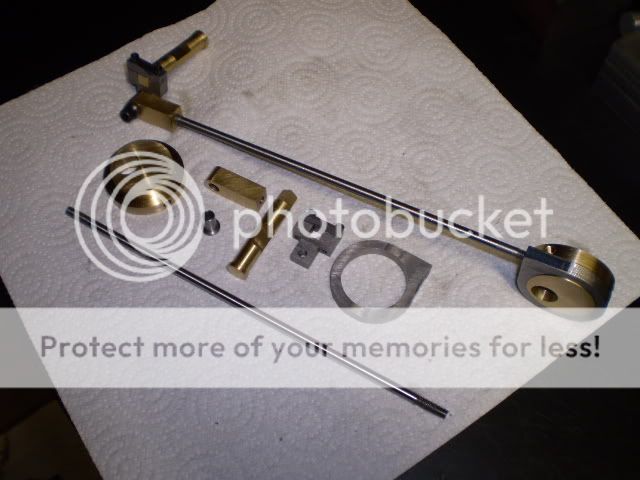
My next post will be a completed engine. Im making a baseplate from wood to test out my dimensions, then later Ill use a piece of aluminum plate. Once I get the dimensions correct, Ill pin the crank webs to the crankshaft with some #8 set screws.
Cheers,
Phil
So I made two eccentrics this week that differ in minor diameter by 0.001. I turned each one to fit one of the straps. I like a nice close fit here, probably closer than necessary. Ive begun to realize making this two cylinder engine that a new challenge arises in a multi cylinder engine, ie, keeping track of what pairs of interacting parts go together. Im using witness marks to keep track of mating parts. Maybe that will be my next engine a multicylinder with completely interchangeable parts. Sounds easier than it probably would be.
With 2 drilled/tapped holes for 10-32 set screws the eccentrics are finished.
Here, the straps are fitted onto their corresponding eccentrics.
Next, I fished some ¼ steel scraps from the recycle bin for making two valve arms. Ive deviated from the original plans in making these. Plans call for filing a ¼ square hole in the arm and pinching it onto the valve end with a 4-40 screw. My design is all machine work which is easier to do for me. I milled a ¼ slot in the arm, then made a cap that fits over the slot to hold the valve in place. The slot is milled 0.010 undersize on the vertical dimension so the cap actually clamps the ¼ square valve end. The valve arms are pictured here clamping a piece of ¼ square steel bar to test for fit.
Valves were made from ½ brass rod. I turned them down to a diameter of 0.374 to fit the 3/8 reamed hole in the cylinder block. Then they are milled to produce two flats near the middle to act as open steam ports for each end of the cylinder, thereby producing a double acting mechanism. The completed valves are shown here:
Installed in the one of the cylinder blocks with the valve arm attached to the valve
I had one of those Aha! moments this evening. Im sure this has happened to some of you out there. Machining an engine or other mechanical device requires quite a bit of concentration at times. Ive been working on this engine for over 2 months and Ive been in the trees for so long I wasnt paying attention to the forest! By golly, I dont have that many parts to complete. Steam inlet flanges, crank pins and the baseplate and Im done. Im having déjà vu all over again because it was just about a year ago when I completed my first engine (of this design actually).
I made two sleeves for the valve rod bearings. Learned a good lesson making them too. Wasted time is wasted, no matter how trivial the part. I turned the minor diameter of my first sleeve to a diameter of 0.249 to fit the ¼ reamed hole in the bearing. Next I center drilled it in preparation for drilling a clearance hole for a #10 screw (#9 drill). Then, since I wasnt reading the plans I put a ¼ drill in the tailstock chuck and started drilling away!. If anyone needs proof that 0.249 0.250 is a negative number, I have the proof in the chip pan under the lathe.
Heres a pic of the valve trains, one assembled, the other in parts.
My next post will be a completed engine. Im making a baseplate from wood to test out my dimensions, then later Ill use a piece of aluminum plate. Once I get the dimensions correct, Ill pin the crank webs to the crankshaft with some #8 set screws.
Cheers,
Phil
Philjoe---This may be kind of a dumb question, but how are you going to drive anything with your twin cylinder engine. Based on what I see of your photoshopped image at the beginning of this thread, the only way you can take off a drive from this engine is off the outer diameter of the flywheel. When I designed my twin, I considered doing it exactly as you show, but the thing that kept me from doing it that way was the inability to have an exposed driveshaft to put a pulley on.---Brian
Philjoe5
Well-Known Member
- Joined
- Jul 12, 2007
- Messages
- 1,727
- Reaction score
- 321
Brian,
Not a dumb question at all. Answer: being a mechanical newbie, I hadnt thought that far ahead ;D. No actually, I probably wont drive anything off of this engine. But correct me if Im wrong, couldnt you belt something off of the central flywheel as long as you elevated the driven pulley like in a lineshaft arrangement. Maybe even a friction drive with a rubber wheel on a small generator shaft placed against the flywheel? The engine Ive sort of modeled mine after is shown here:
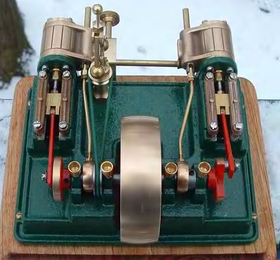
It was a model engine for sale on eBay a year ago. I forgot who was selling the castings for it.
Cheers,
Phil
Not a dumb question at all. Answer: being a mechanical newbie, I hadnt thought that far ahead ;D. No actually, I probably wont drive anything off of this engine. But correct me if Im wrong, couldnt you belt something off of the central flywheel as long as you elevated the driven pulley like in a lineshaft arrangement. Maybe even a friction drive with a rubber wheel on a small generator shaft placed against the flywheel? The engine Ive sort of modeled mine after is shown here:
It was a model engine for sale on eBay a year ago. I forgot who was selling the castings for it.
Cheers,
Phil
Generally speaking, the flywheel is way too large to take a drive off of. The drive pulley should be in the range of 1" to 1.75" diameter in order to give the correct mechanical advantage required to run something off your engine. As I said previously, I seriously considered building my twin the same as yours, because it makes it so much simpler, but I abandoned that idea so that I would have a crankshaft to mount pulleys on. The trouble with building an engine just to see if it will run, is that once you have established that it will run, there is nothing more that you can do with it.
kellswaterri
Senior Member
- Joined
- Oct 14, 2007
- Messages
- 117
- Reaction score
- 6
Hi Brian, I would have to disagree on part of your post...
''The trouble with building an engine just to see if it will run, is that once you have established that it will run, there is nothing more that you can do with it''.
I and quite a number of others are working on utilising these little engines to drive Dynamoes or power minature factories...do not just build an engine and let it idle its life away by sitting on a shelf some where... put it to WORK...
Brian, if I have misunderstood your post, my apologies...
All the best for now,
John.
Brian Rupnow said:The trouble with building an engine just to see if it will run, is that once you have established that it will run, there is nothing more that you can do with it.
Hmm... perhaps we have swerved into a philosophical issue.
") I have thought about this quite a bit, and I have to admit that, for me, most of the fun is in the preparing to build, the building, and the finishing. After that, my engines get run occasionally, but mostly give me enjoyment just by being there.
I have thought about this quite a bit, and I have to admit that, for me, most of the fun is in the preparing to build, the building, and the finishing. After that, my engines get run occasionally, but mostly give me enjoyment just by being there. Would my enjoyment be enhanced if I coupled some of them to either real-life working loads (blender, condensate pump, etc.), or scaled loads? Perhaps, but I'm not sure it's worth the effort for the added pleasure it might bring. But this is just me. For me, it's all about the engine, building it, running it, and displaying it, for myself and others. If someone asks, "Yes, but what does it do?", then it just tells me that they don't "get it". :-\ (Yes, Virginia, it's a sickness...
)Paula
(PS - Phil, I'm really enjoying this thread. Thanks for taking the time to document your progress for us! Nice work!)
- Joined
- Jan 3, 2008
- Messages
- 2,085
- Reaction score
- 17
I would like to second Paula's thoughts. For me its not how often they run, or what if anything they power while running...but rather that they do run , and will run at the lowest possible air/steam pressure which my skills will allow. After that, even sitting on the shelf, I still know what they are capable of and that alone brings satisfaction.
BTW, the twin shown in Phil's post above in PM Researche's #7BI engine and is still available.
Phil, I am enjoying this thread also...beautiful work!!
Bill
BTW, the twin shown in Phil's post above in PM Researche's #7BI engine and is still available.
Phil, I am enjoying this thread also...beautiful work!!
Bill
Philjoe5
Well-Known Member
- Joined
- Jul 12, 2007
- Messages
- 1,727
- Reaction score
- 321
Thanks for all the support and encouragement. Yes, I'm more in the Paula and
Bill camp here. My satisfaction comes from building a piece of machinery and watching it run "at the lowest possible air/steam pressure which my skills will allow". I have some other single cylinder engines I can more easily belt up to drive something if I feel the need to do that. OTOH Brian I can easily see where you're coming from, especially since you have spent your career designing machines to do something quite useful.
OK, enough of this blathering : on my part, I have a few more parts to make. Then, the required pics and video, and then ?
Cheers,
Phil
Bill camp here. My satisfaction comes from building a piece of machinery and watching it run "at the lowest possible air/steam pressure which my skills will allow". I have some other single cylinder engines I can more easily belt up to drive something if I feel the need to do that. OTOH Brian I can easily see where you're coming from, especially since you have spent your career designing machines to do something quite useful.
OK, enough of this blathering :
on my part, I have a few more parts to make. Then, the required pics and video, and then ?Cheers,
Phil
Don't get me wrong. There is a tremendous amount of satisfaction in building an engine "just to see it run". My first 3 engines that I built were exactly like that. I was so blown away by the fact that I could actually create an engine that would run, under its own power. By the time I started to design my twin, I was confident that I could build an engine that would run. I needed a new challenge---perhaps the next stage of steamengineitis. I thought that it would be rather pointless to fill my office up with little steam engines, whether they ran well or not. My focus now, at least for a while, will be to build "things" that a steam engine will power.---Brian
Philjoe5
Well-Known Member
- Joined
- Jul 12, 2007
- Messages
- 1,727
- Reaction score
- 321
I hear ya Brian. I'm still in stage 1 of "steamengineitis". But I must say I've got your slinky machine plans and I'm watching your flyball project with great interest...so I'm preparing for stage 2 when or if it comes :big:
Cheers,
Phil
Cheers,
Phil
ChooChooMike
Well-Known Member
- Joined
- Jan 5, 2008
- Messages
- 864
- Reaction score
- 13
It'll come, just wait for it , it'll sneak up on you very slowly .....
, it'll sneak up on you very slowly .....Cedge
Well-Known Member
- Joined
- Jul 12, 2007
- Messages
- 1,730
- Reaction score
- 29
Move over Paula, Bill, Phil...
I'm on the same bench. The journey is where I have the most fun. That was true even before I began building my own engines. Rescuing a forsaken family heirloom and restoring it to as good or better condition than when it was built gave me the same sort of energy jolt. Knowing it was sitting on the shelf and ready to run was enough... if you add in the knowledge that one more engine did not become scrap yard fodder. That was not nearly an uncommon fate in pre-Ebay times.
It's one of the beauties of the hobby. I can build and or collect based on my own criteria. I like those with unique and unusual mechanical actions. My ideal collection would have one of each mechanical function ever used to build engines. Others prefer historical accuracy, a single model supplier's line, trains, boats.... and yes steam powered slinky machines. They have their place as well.
Point being mine don't have to do anything but please me in my own needed way. That I can enjoy Brian's having to earn their keep is a nice plus for both of us.
Steve
I read you Paula.... when I'm asked "but what does it do?"... my response is that "it gives me pleasure." If they have to ask, no amount of explanation is going to provide an adequate answer.