A portable engine

Home Model Engine Machinist Forum

Help Support Home Model Engine Machinist Forum:

This site may earn a commission from merchant affiliate links, including eBay, Amazon, and others.
Hi

Long time no see. I have had some domestic duties to attend to and had a 1 week holiday in New York, fabulous ;D ;D

Anyway today was fathers day so I was allowed out to play for a while.

The valve chaest wa parted from its parent material leaving enough spare.

DSC02363.jpg


Set up and faced in the 4 jaw.

DSC02366.jpg


In the mill I used a laser centre finder to locate the centre then lightly centre drilled.

DSC02372.jpg


Back in the lathe I set it up accurately with a spring loaded centre and a dial guage.

DSC02375.jpg


Then turned the spiggot (the bit that is the guide for the slide valve rod.

DSC02377.jpg


Then using a ball turner to round over the end. This is the first time I have used the ball turner on a job.

DSC02381.jpg


DSC02386.jpg


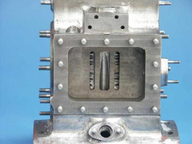
The valve chest was used to mark the position of the first stud hole which was then drilled and tapped 7 BA. I'm using 3/32 stainless steel for the studs which takes a 7 BA thread easily. I have a stock of 7 BA brass nuts. I made up a couple of studs to keep the valve chest in position. The valv chest was placed over the first stud and held while the second hole was drilled and tapped. Once 2 studs were in I could drill and tap the remaining holes using the valve chest as a guide.

DSC02387.jpg


DSC02391.jpg


DSC02393.jpg


I made up 10 studs which are slightly over long at the moment but will be trimmed on final assembly.

DSC02395.jpg


The studs fitted and the valve chest tried for fit. Its just a touch tight at the moment and won't quite go on but the holes in the valve chest were drilled 3/32 so will stand having a clearance size drill run through.
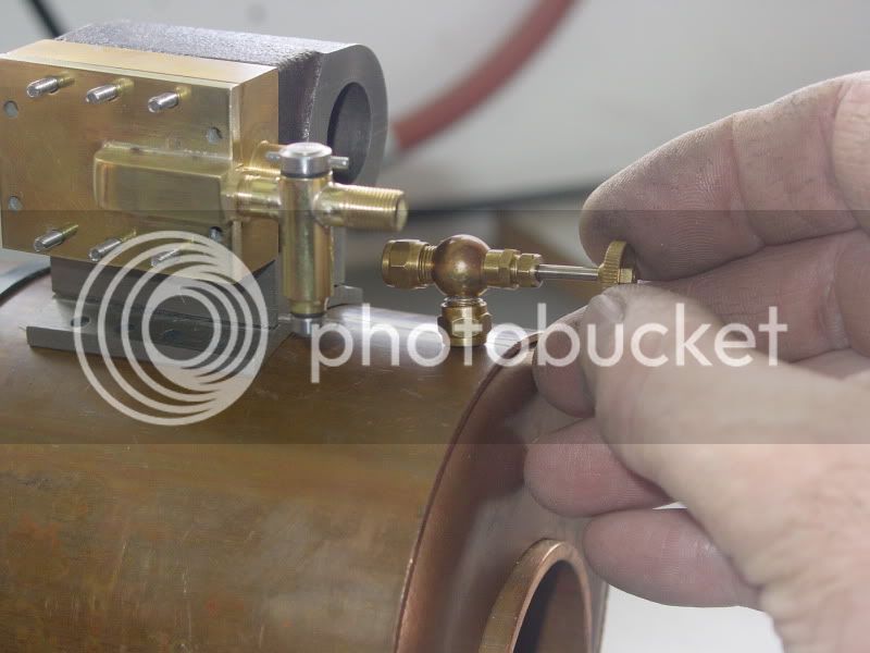
DSC02397.jpg


DSC02399.jpg


Sat on the boiler.

DSC02400.jpg


Cheers

Rich
 
Thm: Coming along very well Rich :)

Are you going to make a separate valve plate, or just run the valve on the cylinder casting ?

Kind regards, Arnold
 
Hi Arnold

Just run it on the cylinder casting. I'll probably make the valve from a bit of phospher bronze. Although I intend to run the engine on steam it won't get enough use to worry about wearing it out.

Cheers

Rich
 
Hi

Clearance holes and the valve chest fits ok.

DSC02412.jpg


DSC02411.jpg


I started making the valve chest cover tonight from a piece of 1/8 brass. After drilling the first hole I used one of the studs to hold it together.

DSC02420.jpg


Another hole was drilled and fitted with another stud then the remaing holes drilled.

DSC02428-1.jpg


Cheers

Rich
 
Hi

I finished off the valve chest cover then had to spend quite some time thinking scratch.gif scratch.gif

On the original plans I have a hole is drilled in the top of the boiler and the cylinder block sits directly on top with steam being admitted to the valve chest through chambers in the cylinder casting via a regulator valve. Because I have fabricated the cylinder it won't be possible to use that method. I have decided to screw a valve into the top of boiler from which a short pipe will deliver steam to a displacement lubricator fitted to the valve chest cover and directly into the steam chest.

This first picture shows the cylinder and a small valve I have (picked up at a steam fair) that I might use. Also a piece of 5/16 square brass that I have rounded over at one end.

DSC02430.jpg


In the 4 jaw chuck the square brass is drilled and tapped 1/4 X 40.

DSC02435.jpg


Then cross drilled 1/8.

DSC02437.jpg


A corresponding 1/8 hole is drilled in the valve chest cover.

DSC02443.jpg


The 2 pieces are silver soldered together.

DSC02448.jpg


After a clean up it looks Ok

DSC02463.jpg


I have started on the lubricator (A John Bogstandard design) and will post pictures later.

Cheers

Rich
 
Hi

The displacement lubricator is a design by John Bogstandard :bow: and one that I have used twice before. Once on my small steam plant and once on the beam engine. I haven't worked to any drawings but to give you an idea of size the body is 7/8 inch long.

Hold a piece of 5/16 brass in a collet and drill down 5.5mm.

DSC02449.jpg


Slightly taper the hole with a centre drill, this will help the O ring seat better.

DSC02450.jpg


Tap 1/4 X 40

DSC02451-1.jpg


Centre in the mill and cross drill 1/8

DSC02458.jpg


Part off and face to length then add a bit of shape with a round profile cutter

DSC02481.jpg


Drill through

DSC02486.jpg


And tap 1/8 X 40

DSC02487.jpg


This is for the drain bung.

The 2 side connections are made from 1/4 round brass. Hold a piece in a collet and thread 1/4 X 40

DSC02454.jpg


Drill through 1/8

DSC02455.jpg


One piece is drilled with a centre drill which is 60° to make a seat for the coned pipe connection

DSC02456.jpg


Part the two connections off and machine to length. They are then screwed into a mandrel in the mill vice and the ends profiled with a 5/16 cutter to match the radius of the body.

DSC02460-1.jpg


A piece of 1/8 copper pipe is accurately centred in the mill. You can just see the red dot of the laser.

DSC02465.jpg
.

Very lightly touch with a centre drill

DSC02470.jpg


Then drill through one side onle with a 1mm drill

DSC02473.jpg


Cut off the pipe to 1 inch long.

A trial fit of the parts

DSC02479.jpg


The drain bung is made from 3/16 stainless steel. Machine down to 1/8 and thread 1/8 X 40

DSC02490.jpg


Cross drill 1/16

DSC02492.jpg


Part off and use the body as a mandrel to hold it in a collet. Face off and profile.

DSC02496.jpg


Press in a short length of 1/16 stainless steel to make the handle.

DSC02499.jpg


The filler bung is made in a similar fashion from 5/16 stainless steel.

The parts so far.

DSC02500.jpg


And loosely assembled for a trial fit

DSC02505.jpg


Set up in the brazing hearth. Make sure the hole in the copper pipe faces upwards. Note the silver solder wire wrapped around the joint area.

DSC02510.jpg


Its in the pickle now having a clean up. I'll show the finished lubricator when its been claned up and polished.

Cheers

Rich


Good going Rich

I see you're also not averse to giving toolmaker's clamps a hard hot time in the hearth.

Kind regards, Arnold
 
Hi Arnold, John

I bought a set of 4 for about £10.00 at a show. Cheap as chips.

Cheers

Rich
 
As an aside, when clamping things tight together for silver soldering, you must ensure that the faces to be joined have pop marks on them to give space for the solder to flow into, 0.002" nominal.

But everyone knows that, as I do know that Richard uses that technique.


John
 
Hi

Yes thats right John, I perhaps should have mentioned it to help those that have yet to try silver soldering. The square piece that is silver soldered to the valve chest cover has 4 light centre punch marks on the valve chest cover to keep the square piece just clear of the surface to allow the silver solder to flow between the 2 parts. The lubricator side connectors are a rough finish and do not fit the body exactly leaving a very small gap for the solder. If you look very closely at the picture of the lubricator clamped ready for soldering you can just see a small gap at the top of the left hand connector. Its second nature for me now and easily overlooked when posting but its a point well worth mentioning.

Cheers

Rich
 
Hi

I had to spend quite some time cleaning up the parts. The valve chest cover had distorted a bit when silver soldering so I had to bring that back to flat with some wet and dry on a bit of glass as a surface plate. After a polish though they are starting to look like something. In this shot of the parts you can see 2 O rings and a thin brass lock nut, 1/4 X 40.

DSC02513.jpg


The parts assembled.

DSC02517.jpg


Sat on top of the boiler.

DSC02520.jpg


This is the valve I will probably use and its likely position.

DSC02521.jpg


DSC02522.jpg


Cheers

Rich

 
Hi

Although this engine is being built without plans as such. much of it so far being built as I go along some parts need to be more carefully worked out. The steam ports and slide valve being a good example. I will only get one chance at machining them so I have to get it right, mistakes can't be rectified. A drawing on the computer gives me a good chance of getting it right first time, hopefully ::) ::)

This is what I am going to do. There is a useful mixture of imperial and metric here. I have a 2mm mill cutter is the reason.

slidevalveandportsjpeg.jpg


Cheers

Rich
 
Its usual to have the exhause larger than the inlets so the steam can get out faster than it went in, I would increase to at least 3mm preferably 4mm

Cyl4.jpg
 
Jason is correct, my engineering book say exhaust =port width x2, the Slide valve moves equally to each side of center position.
 
Hi

Thanks Jason and Don. :bow: :bow:

I somehow figured it wasn't quite right. Thats the great thing about this forum, theres always someone to put you right. Many thanks. I'll amend the drawing and re post.

Cheers

Rich
 
Hi

A question ???

Am I right in saying that in its central position the slide valve covers all 3 ports. When it moves to the right it uncovers the left admission port and when moving an equal amount to the left it uncovers the right admission port.

Cheers

Rich
 
Hi Rich

That's correct. For a simple slide valve, the wall thickness on the port sides are also a fraction wider than the ports themselves to prevent connecting the inlet steam directly to the exhaust while opening.

Kind regards, Arnold
 
hi Arnold

A quick drawing, slightly different to the previous one. This one shows the size of the steam chest.

bggerports.jpg


The admission ports are 2mm wide x 8mm and the exhaust port is 4mm wide x 8mm. There is a 2mm wall thickness between admission and exhaust ports. The slide valve would be 12mm square with 2mm wide walls around the recess. This is about the best I can fit in I think but better than the previous design. What do you think.

Cheers

Rich
 
With that port spacing I would be looking at a 14mm long slide valve (8mm recess and 3mm each end) you could probaly get away with 13mm long (8 & twice 2.5mm) is space is tight

J
 
Back
Top