Lesmo
Well-Known Member
- Joined
- Mar 1, 2011
- Messages
- 142
- Reaction score
- 16
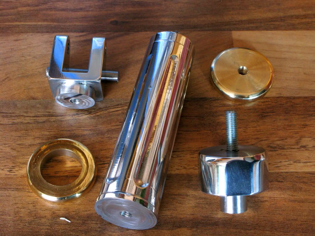
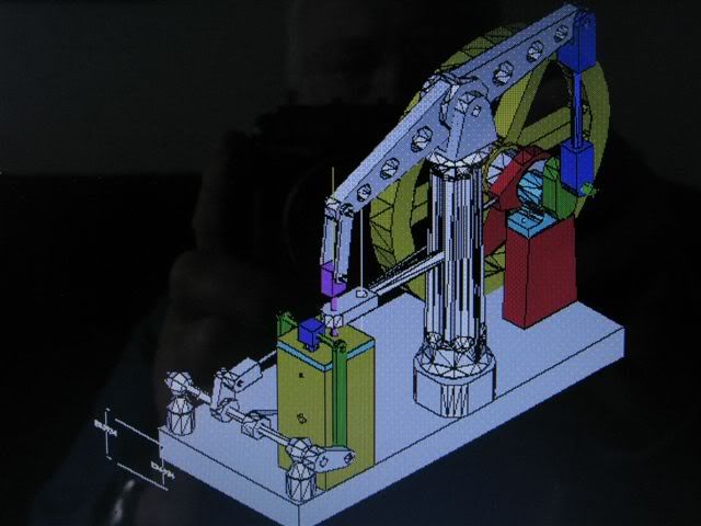
The next logical step will be the column, and I have some ideas for this, that will probably exceed my ability to carry them out. I want make the column round but tapered for the most of its length, and then put in some tapered semi circular recesses for decorative purposes along the length. I also need to make it just over 6mm taller to compensate for the alteration of the beam shape, which effectively lower the end holes by that amount. I want to include some brass to carry on the same motif that I have on the flywheel and beam.
To do this I thought I would make it in several parts, because if I screw up the tapered section which is a strong possibility, then I only have to remake it, or redesign it to a simpler format, also I will simplify the addition of some brass.
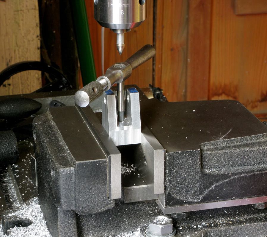
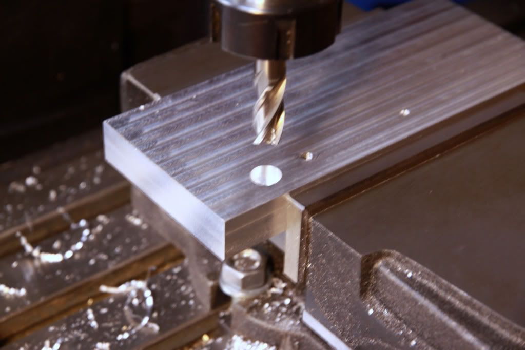
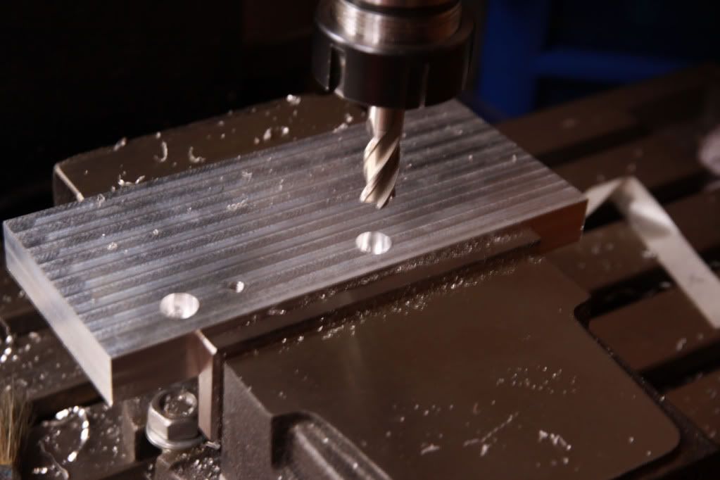
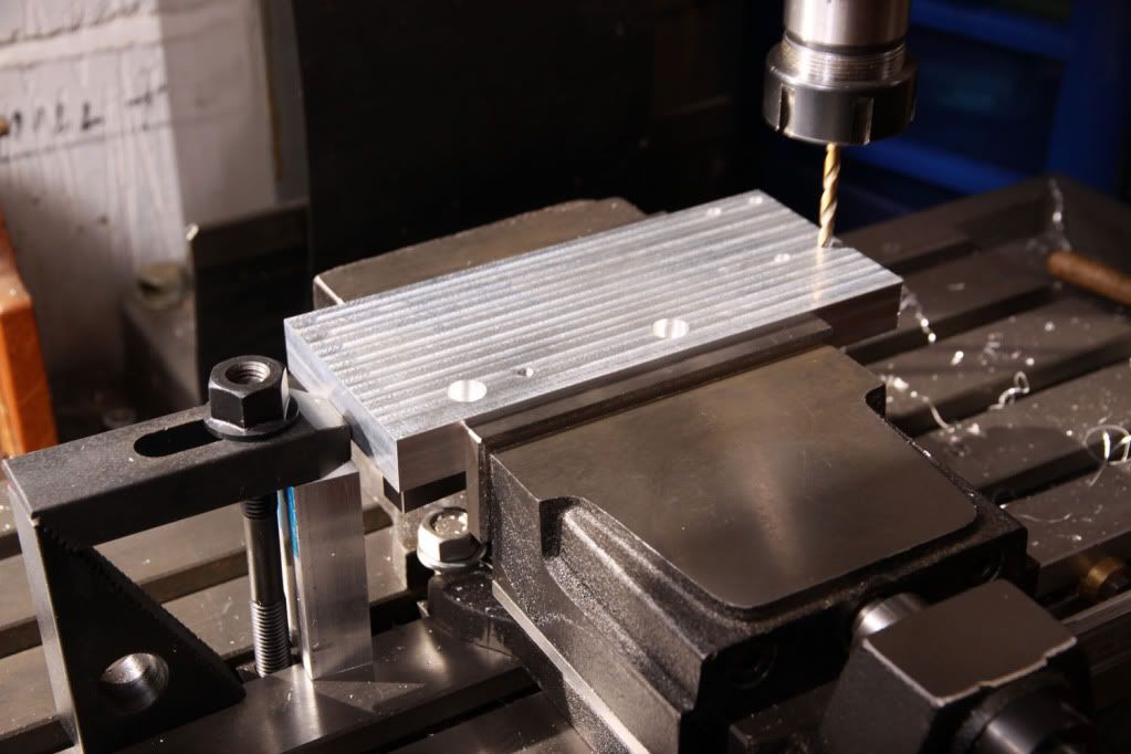
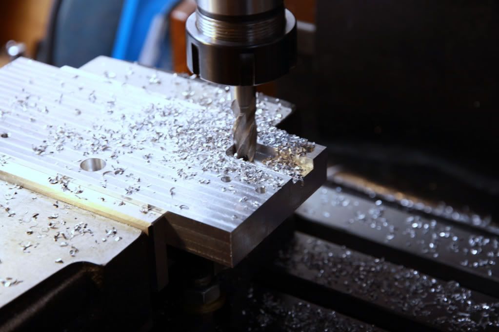
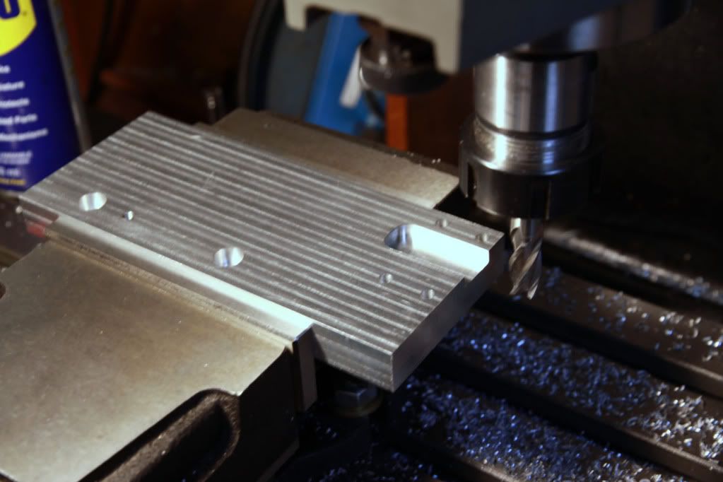
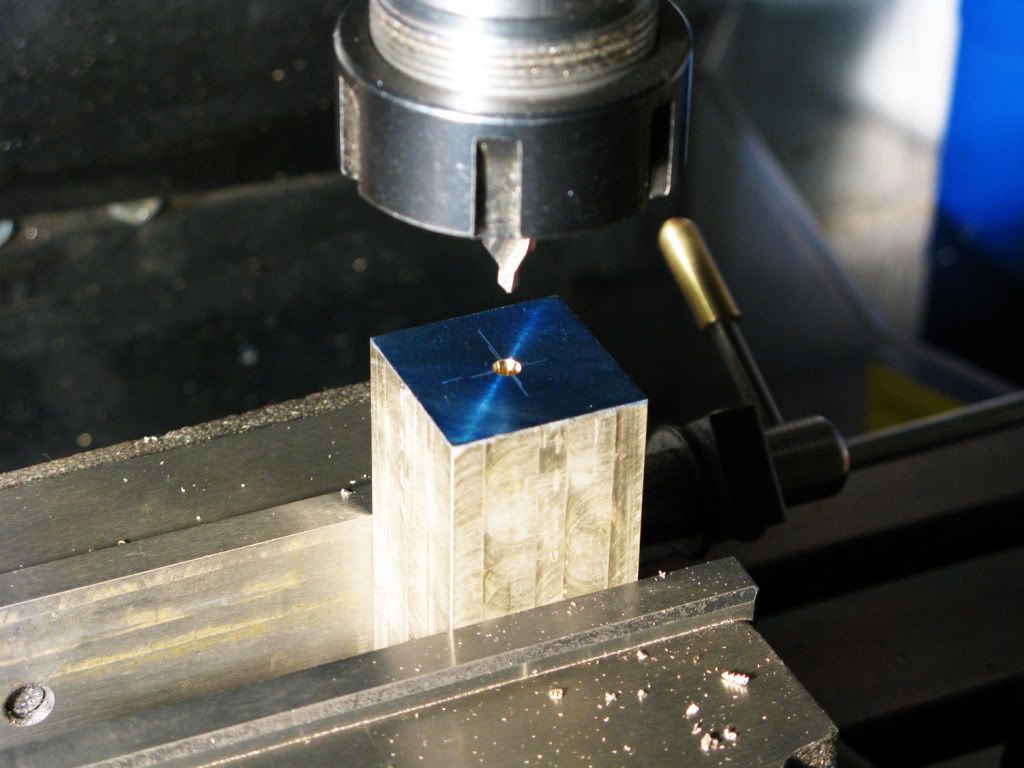
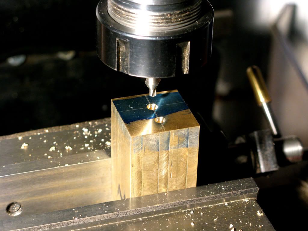
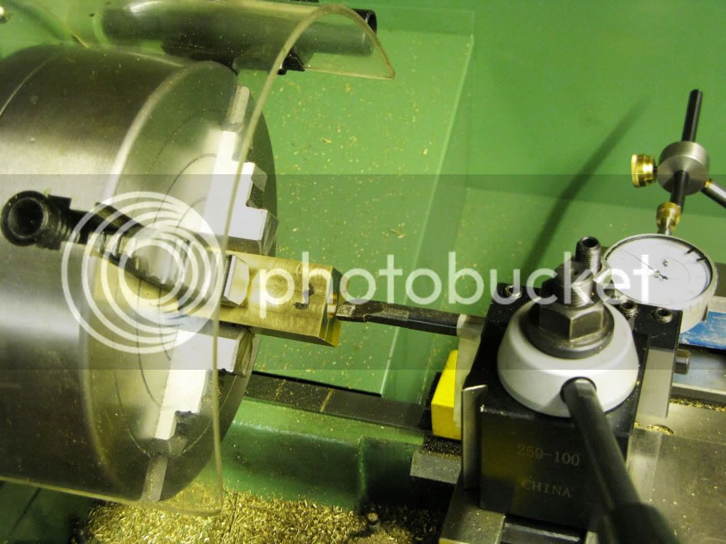
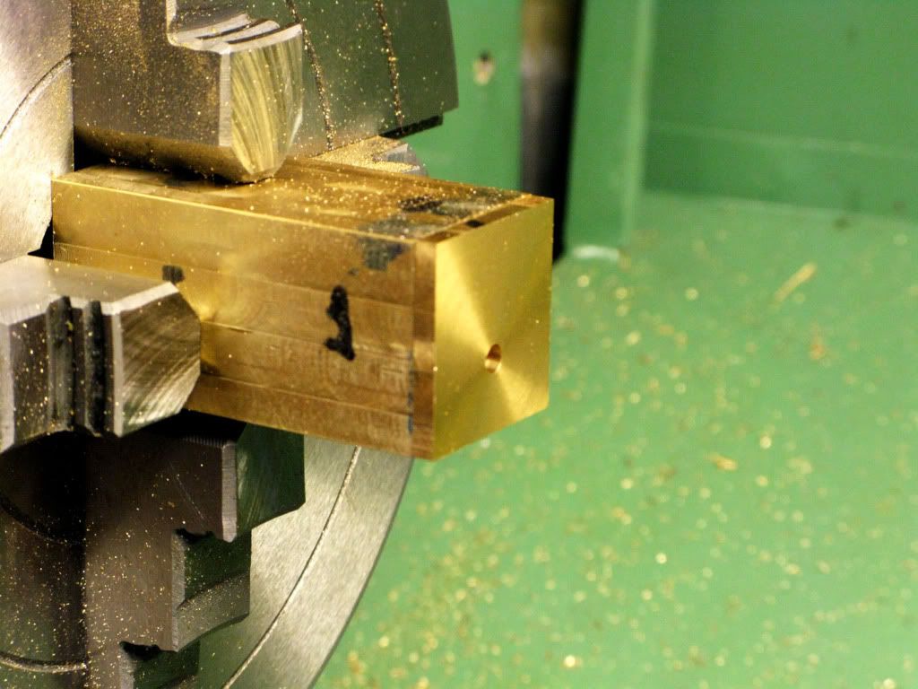
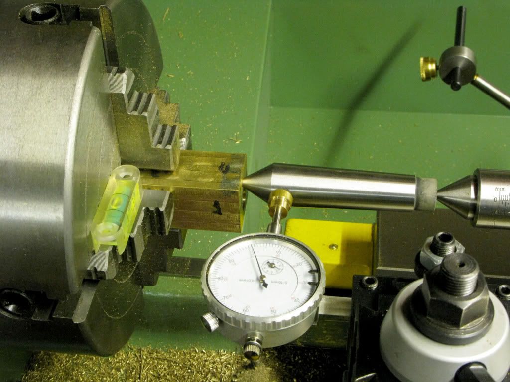
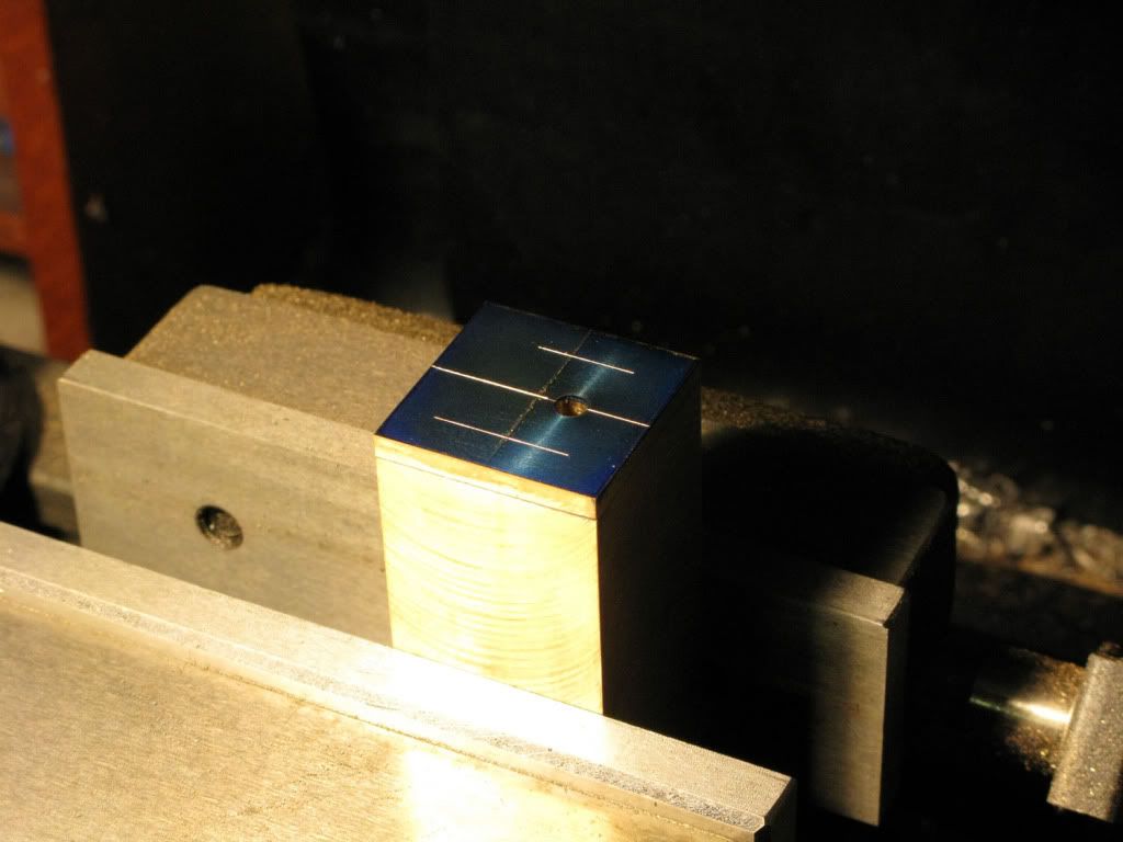
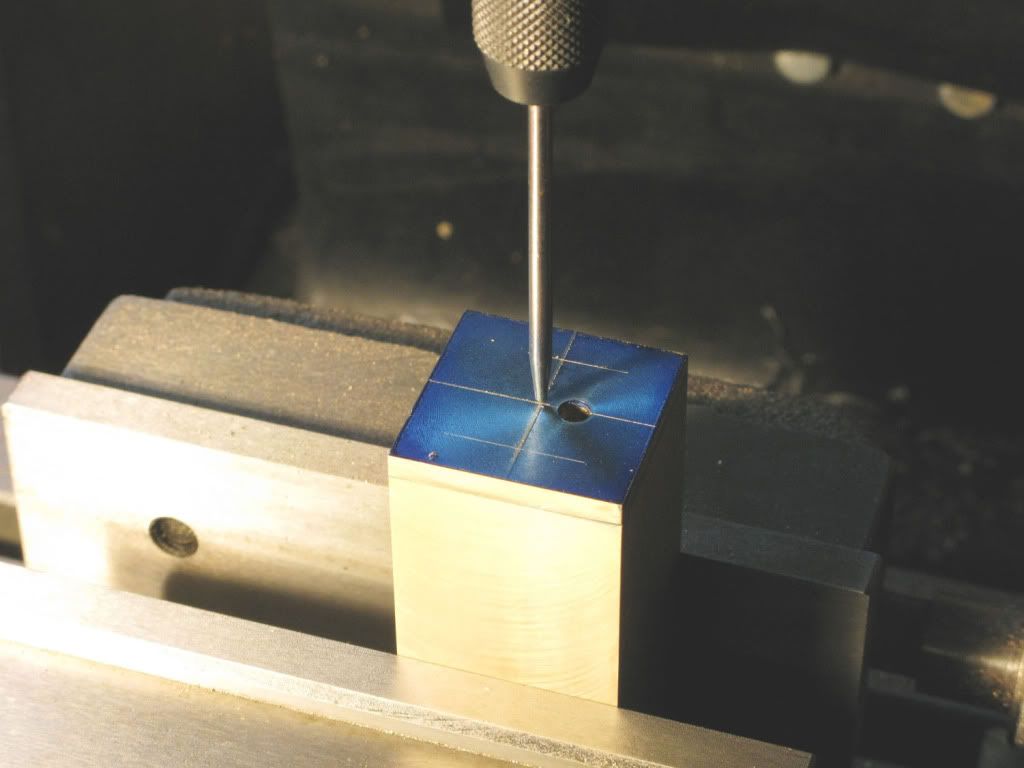
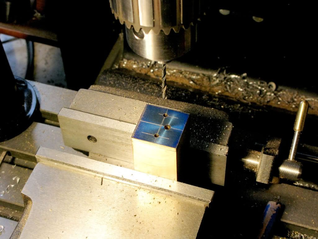
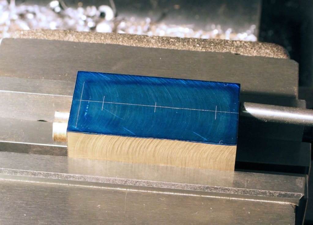
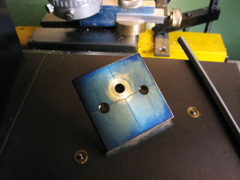
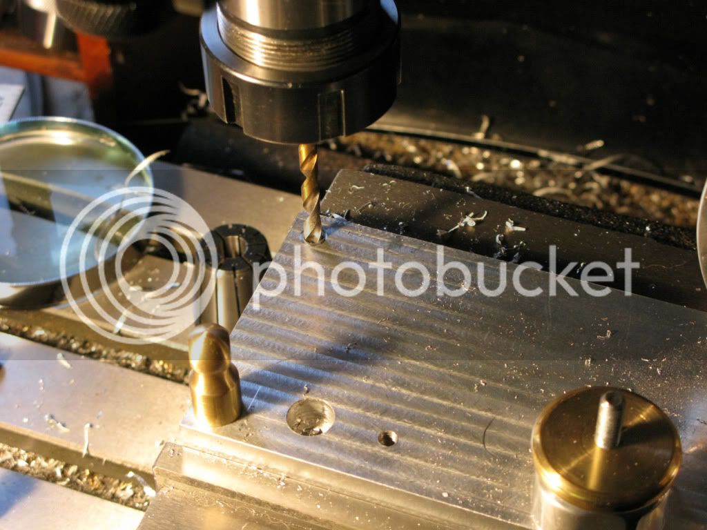
Starting with a more than sufficient length of 32mm square ally I faced one end in the mill, marked the centre and drilled it for the tailstock. I then put the new 4 jaw on the lathe. It was at this point that I realized that Marvs 4jaw setup tutorial described the setup for rounds, so I pondered the problem for a while, then thought about the tiny spirit level I had in my toolbox.
This fit nicely on the flats of the jaws enabling me to get each jaw horizontal, as I followed Marvs instructions moving the level to the opposite jaw as each DI comparison and adjustment was made. Eventually I managed to get the piece centered.
You are probably chuckling at this Heath Robinson method and know of a much simpler one. PLEASE enlighten me.
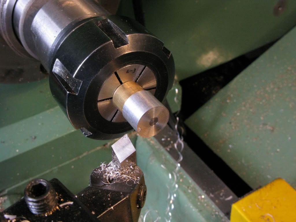
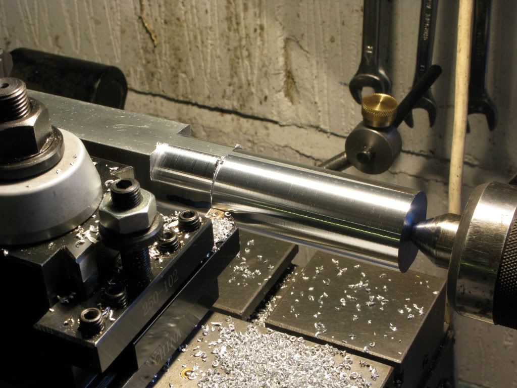
I started by turning the piece so that the rounded section was about 3mm larger than the diameter required for the thickest part of the intended taper and 25mm longer
Now for a venture into the unknown. Turning between centers. Did I chop off the round section and taper that, and if so how would I drive it, or should I leave it be and use the square as a means of drive and again how would I drive it.
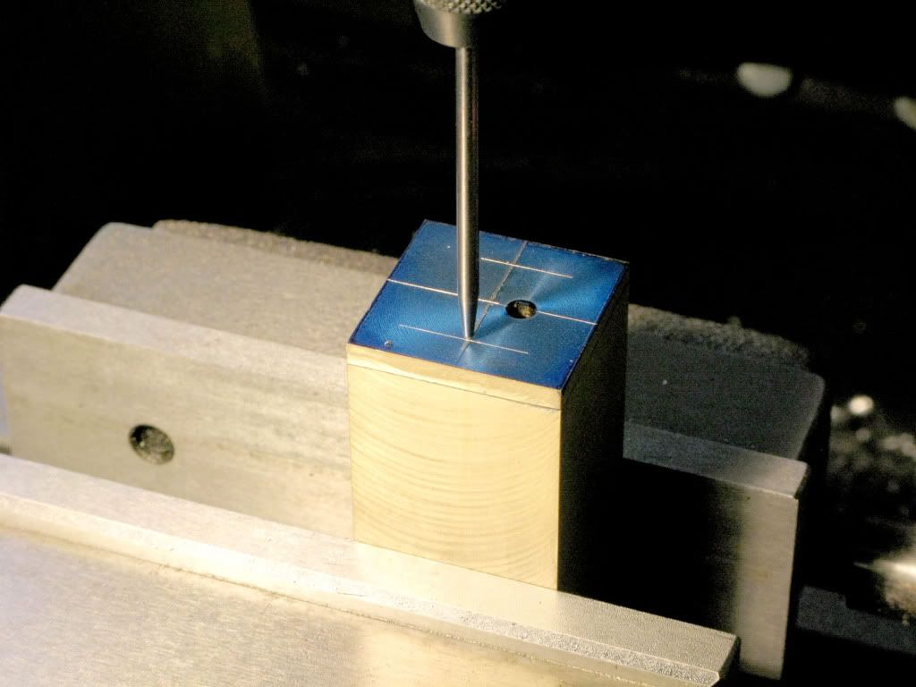
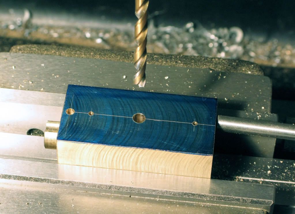
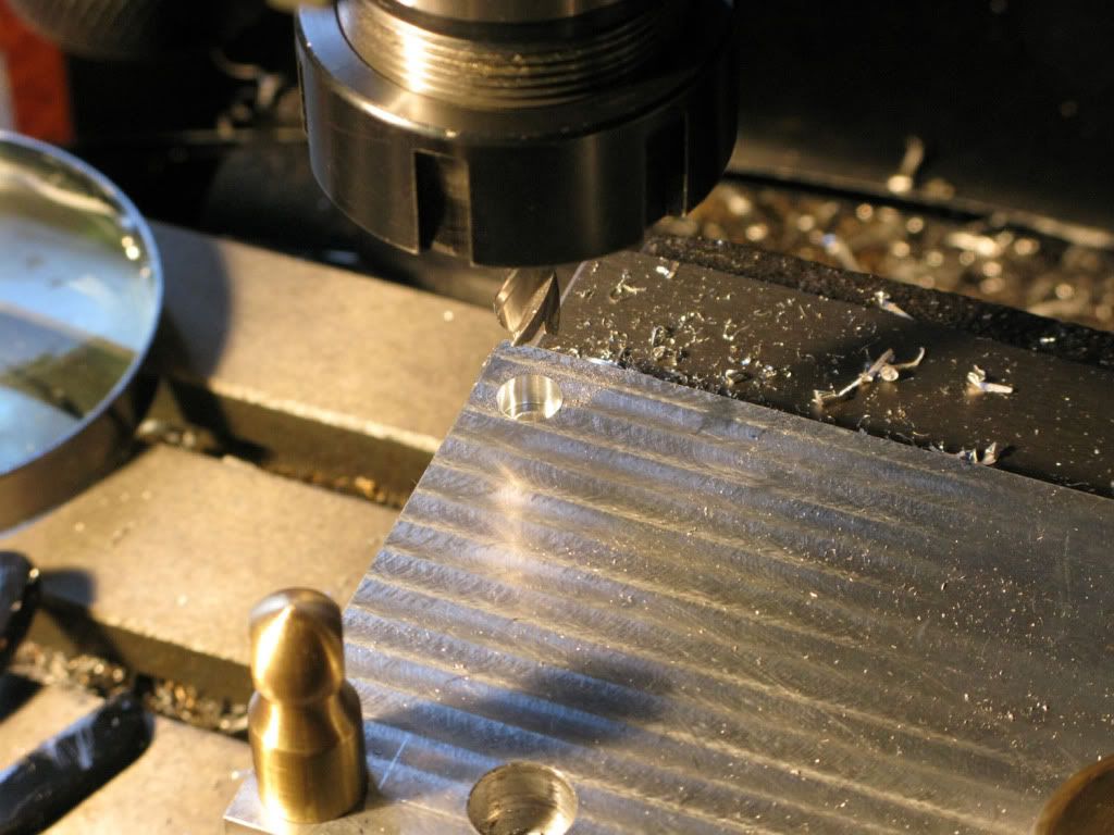
Finally I went for the safer option, faced the square end and centre drilled it.
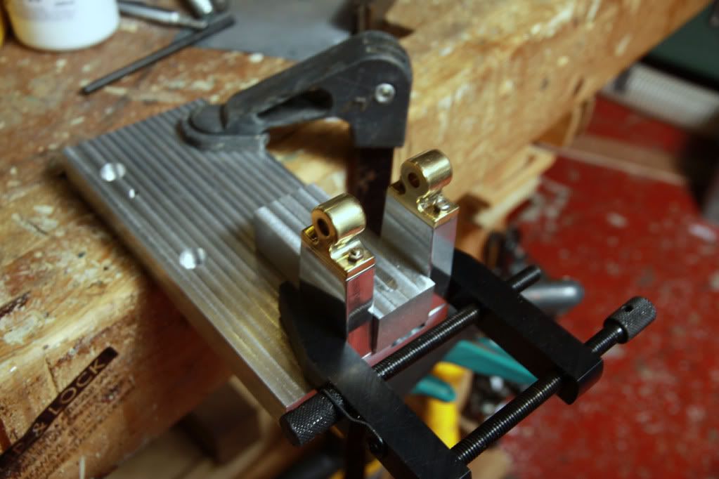
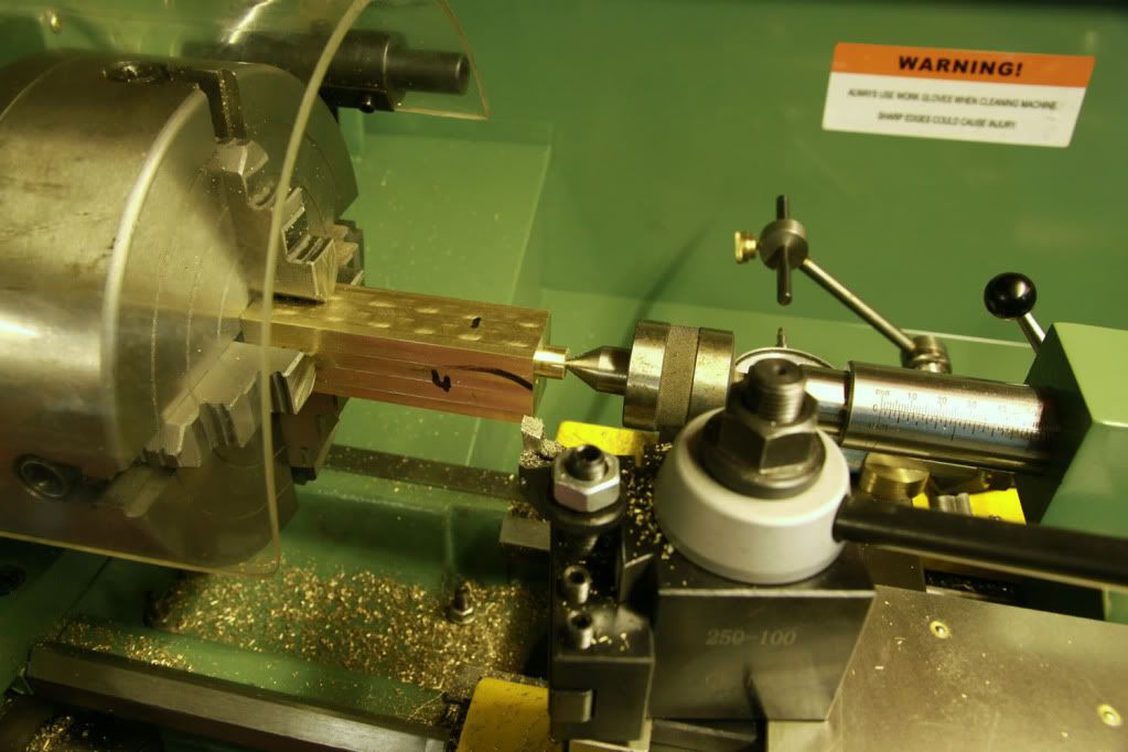
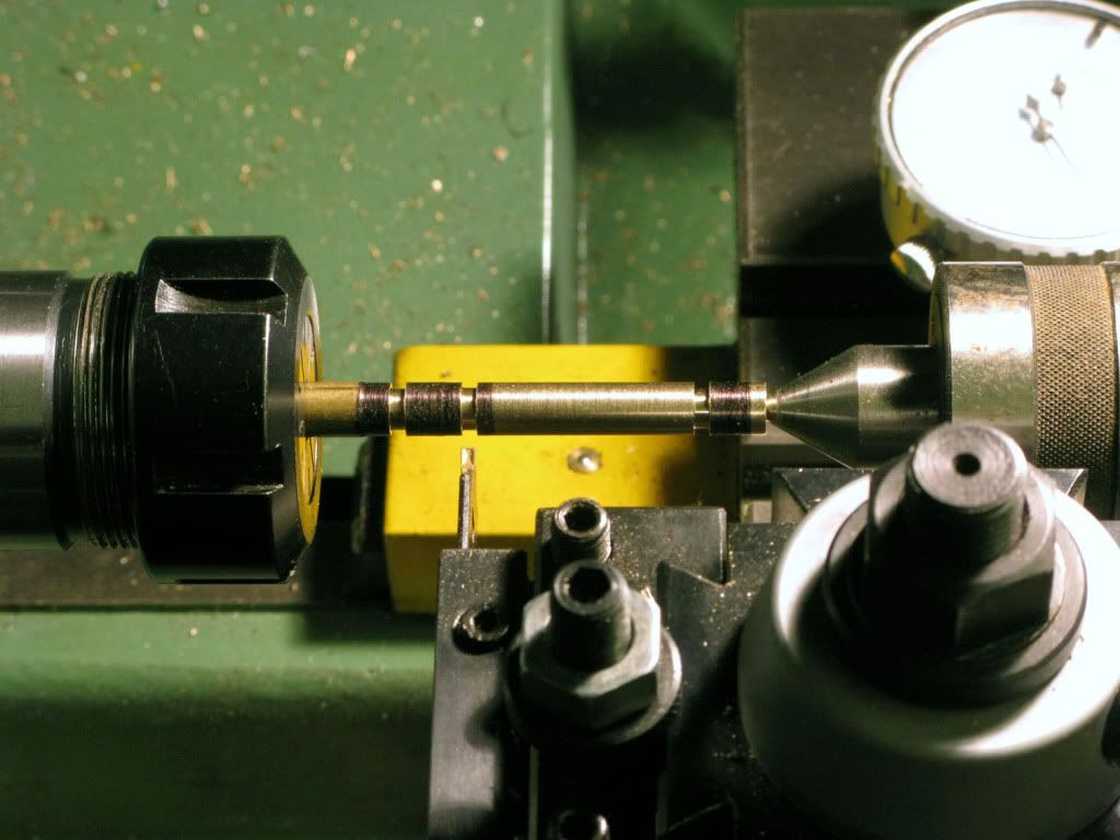
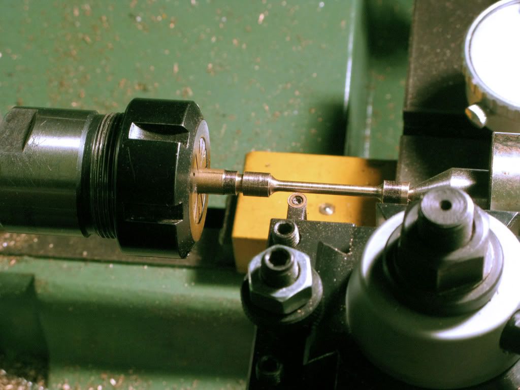
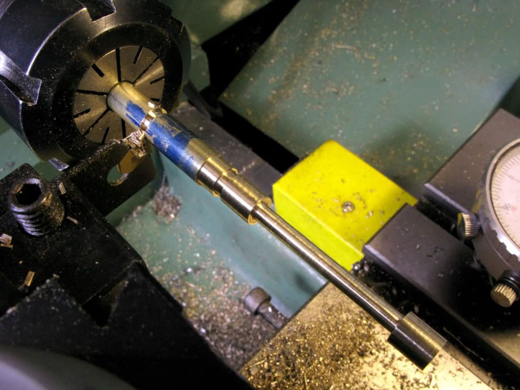
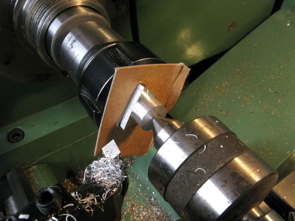
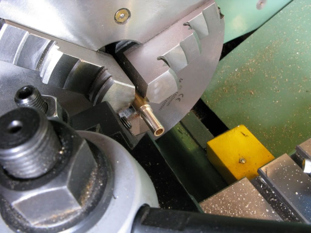
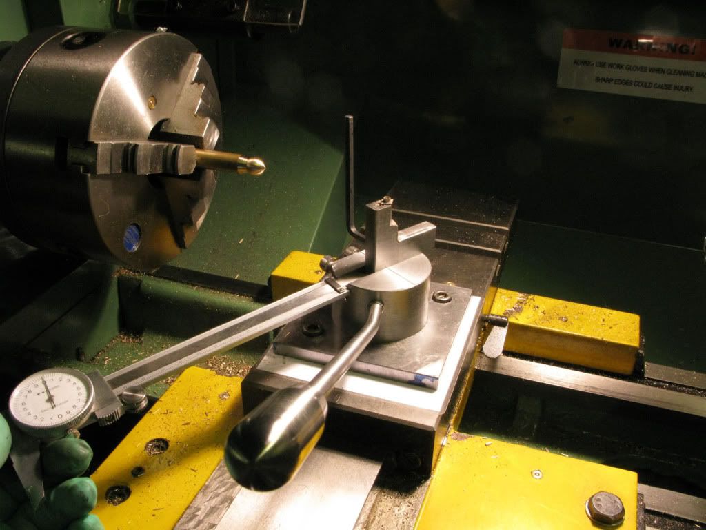
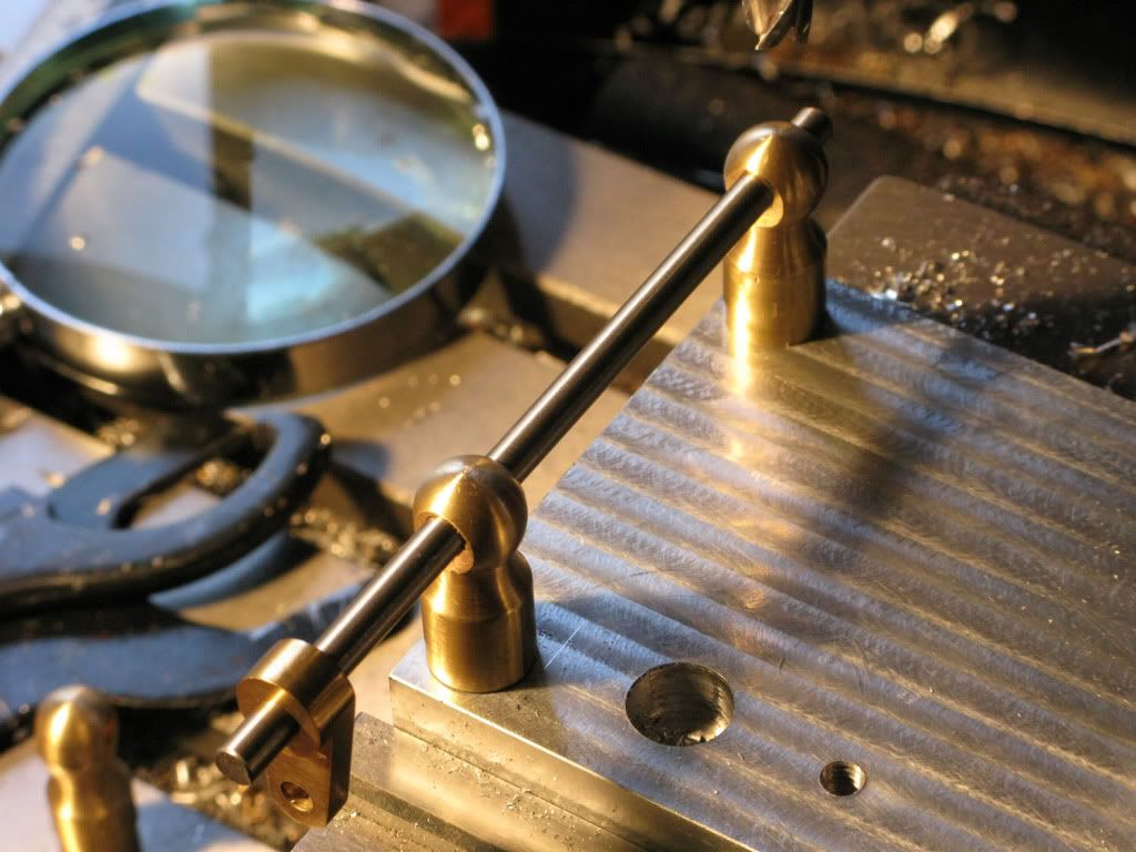
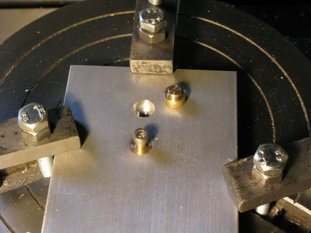
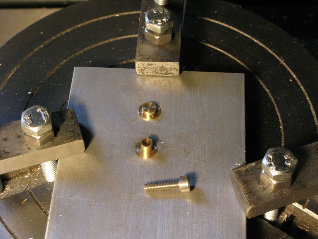
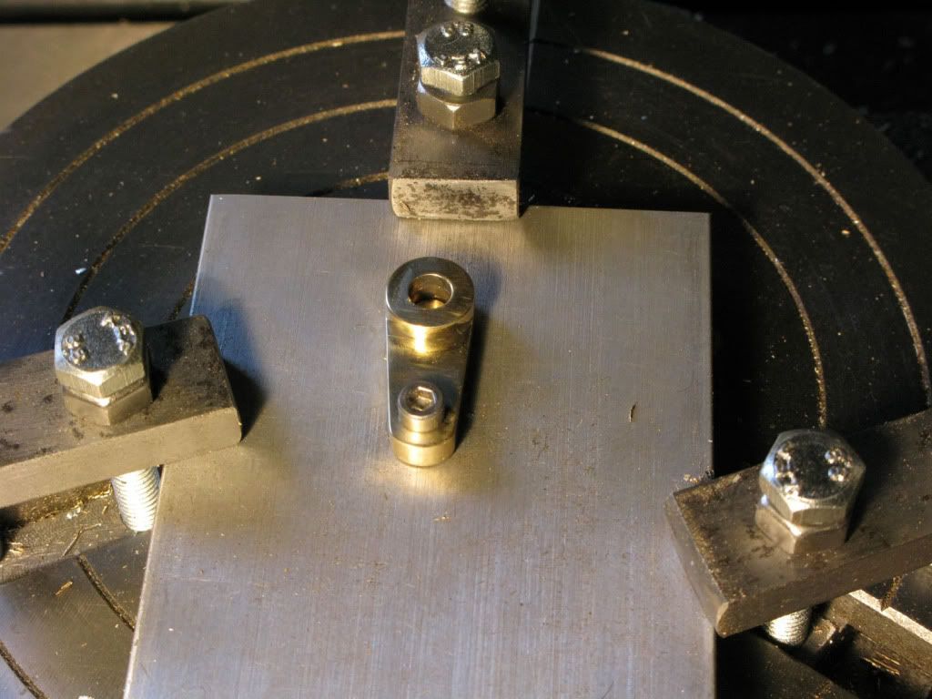
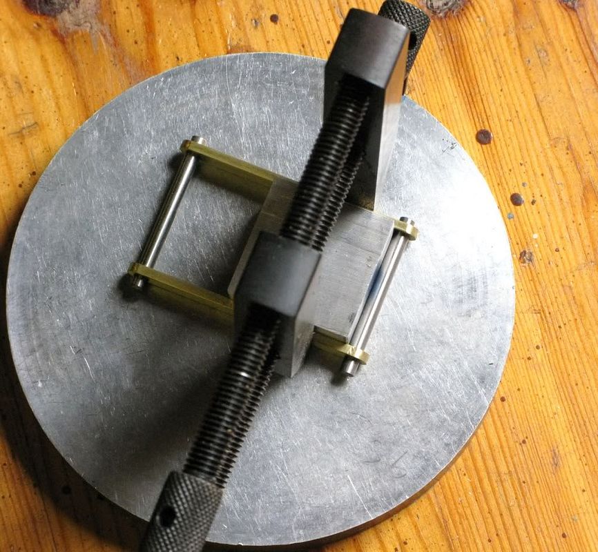
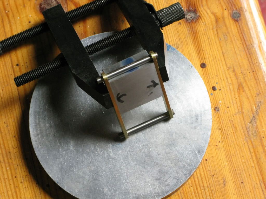
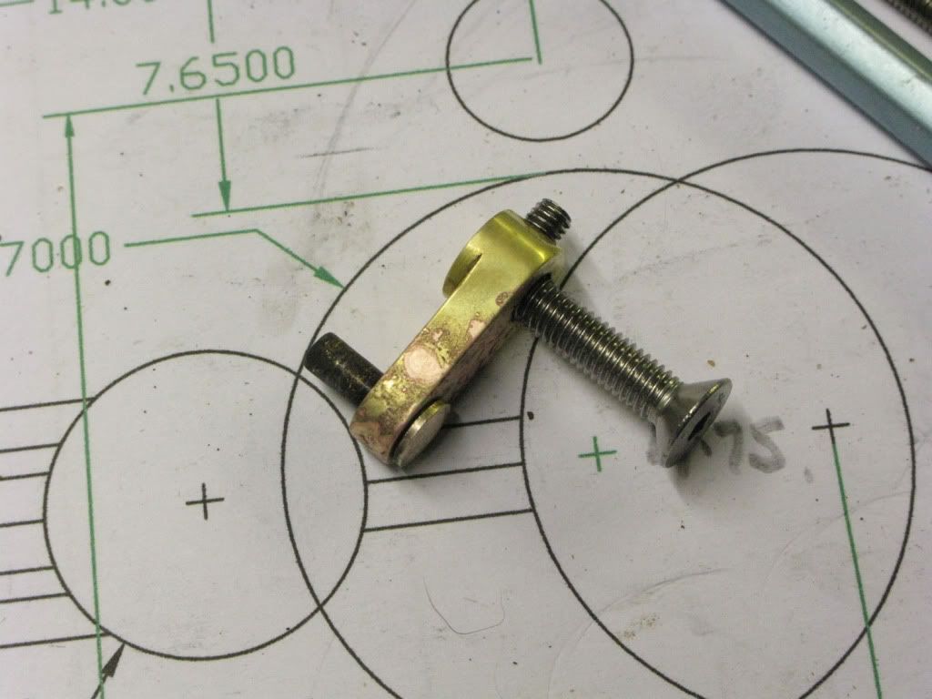
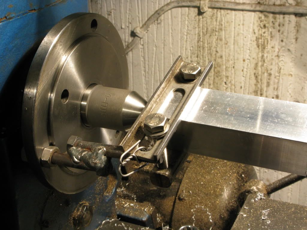
I was flapping so much by now that photography didnt even cross my mind. I had set the work between centers and I had no drive dogs. Time to improvise, with an ancient home made brake hydraulic hose clamp, a couple of long 8mm bolts quickly mig-welded together and a turn of stainless steel tying to tie the bolt to the clamp.
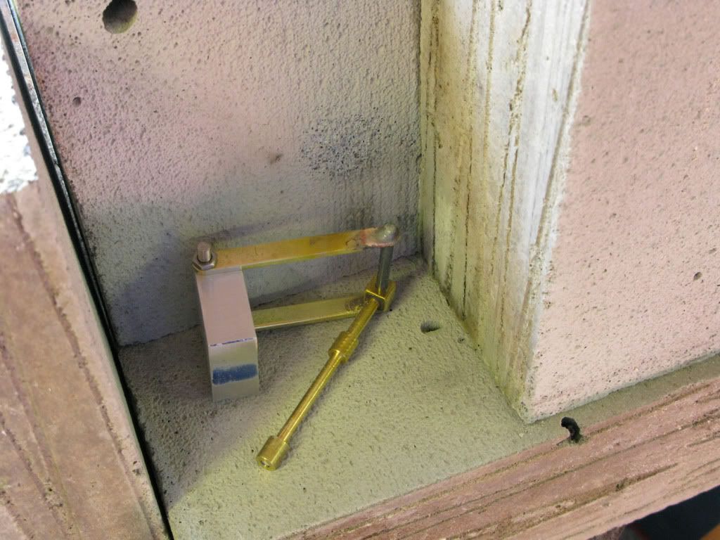
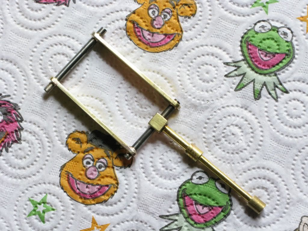
Mockup picture below for your amusement.
I worked out that I needed to offset the tailstock just over 4.5mm to get the desired taper but from time to time the &(*&% thing chattered like a chimp at a tea party, finally I wound the live centre in really hard which cured the problem, and I was able to make the subsequent and final cuts nice and clean.
Is it something I was doing wrong, did I center-drill the holes too deep or what. The previous parallel turning using the same tool was perfect ???? Not an encouraging start to taper turning. However the result was just fine. Comments would be welcome.
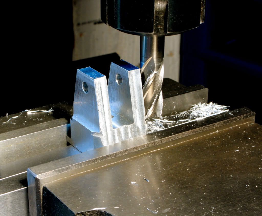
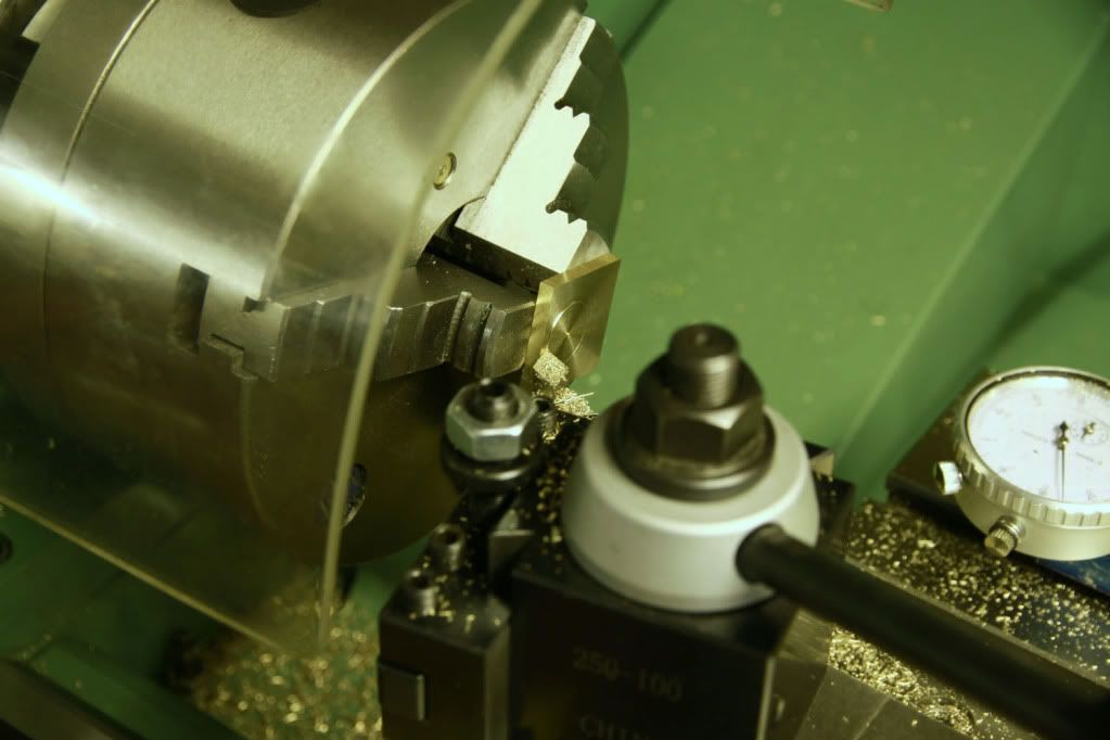
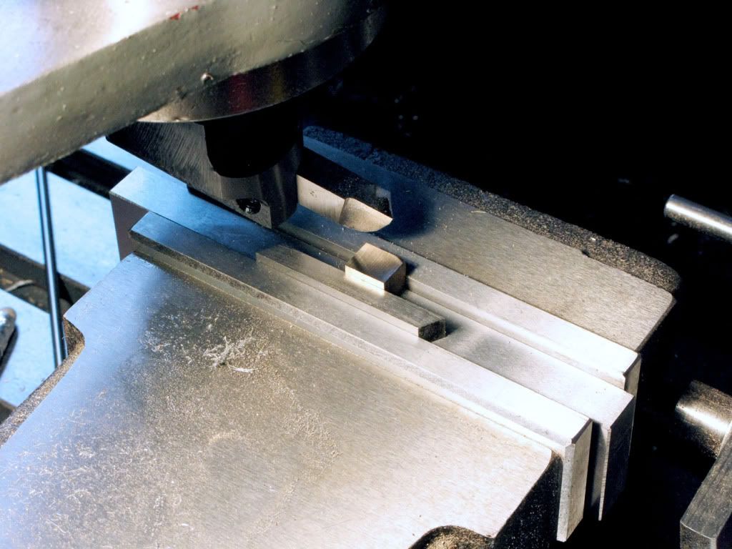
Before removing from the lathe I backed off the tailstock returned it to its original position and wound the tailstock back in, then turned corners off another section of the square stock so that they were about equal to the width to the flats. This would be the base of the column.
Removing it from the lathe I cut off the taper on which I had left 10mm of parallel section at each end, then cut off the piece for the col base.
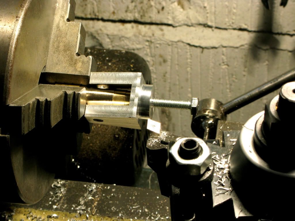
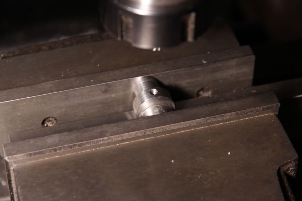
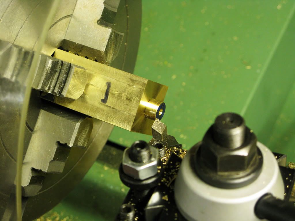
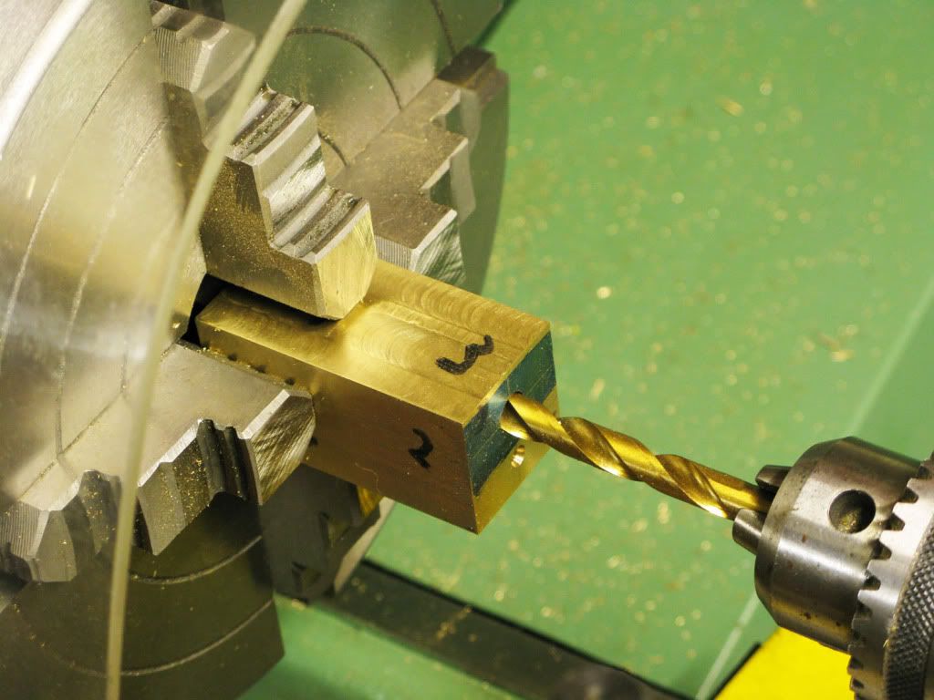
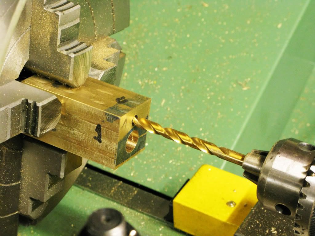
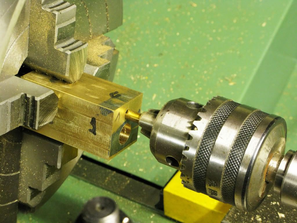
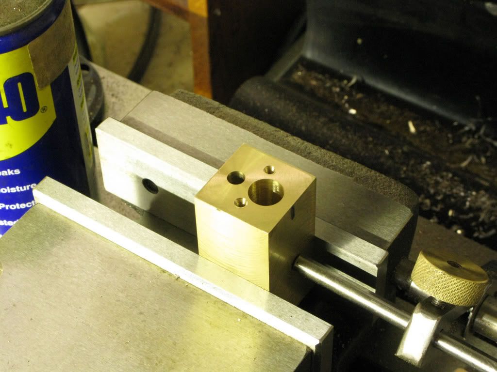
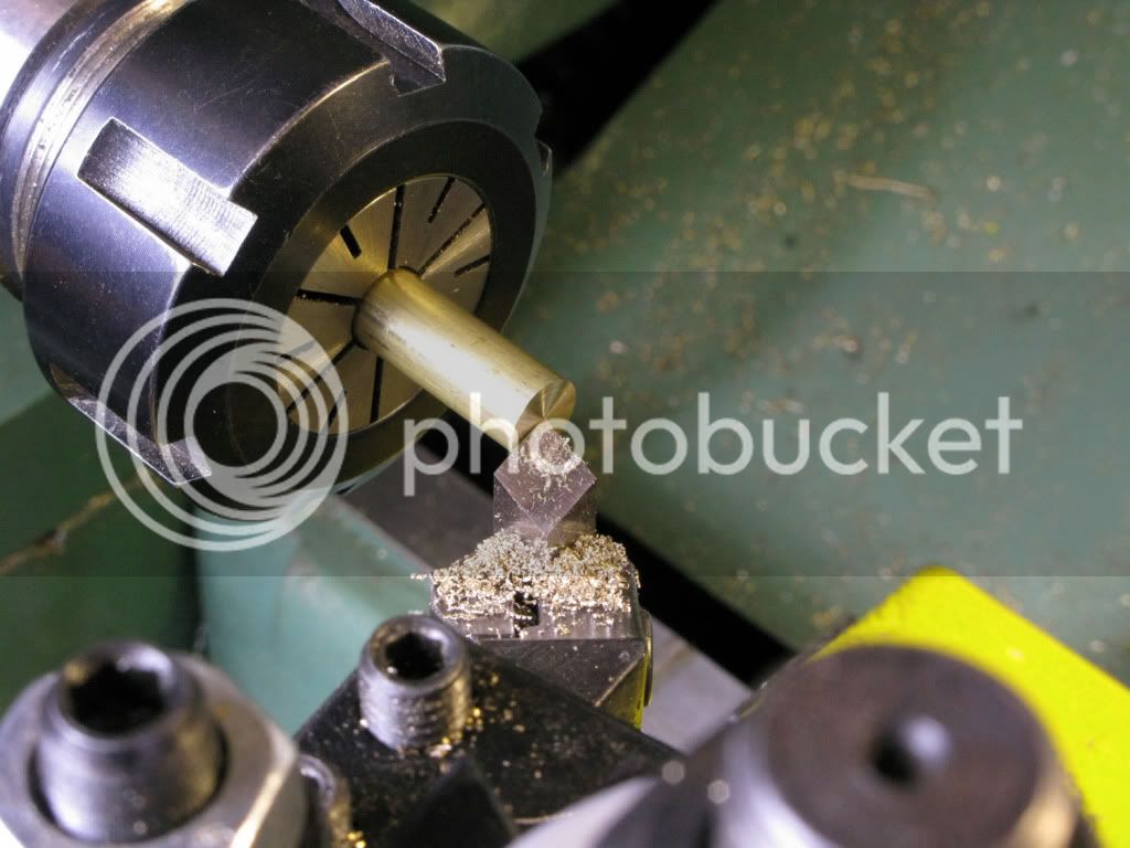
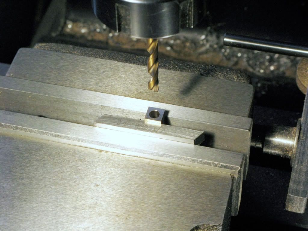
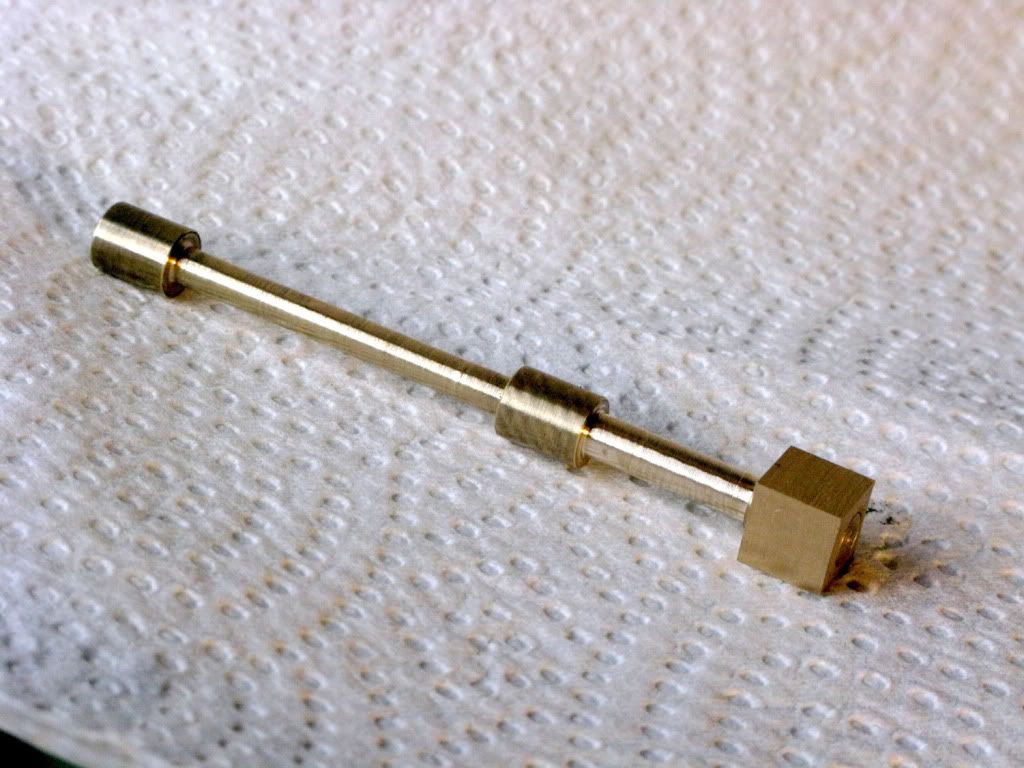
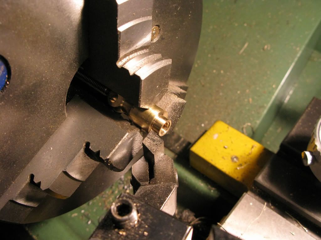
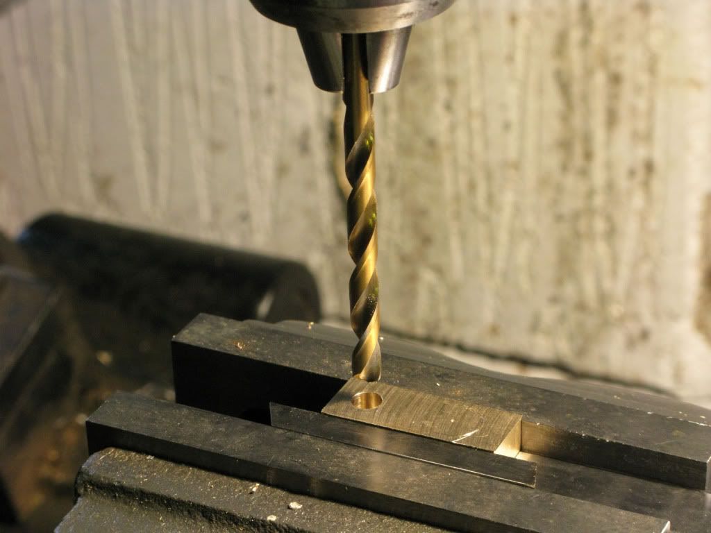
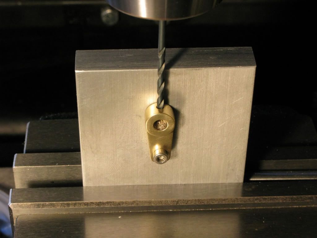
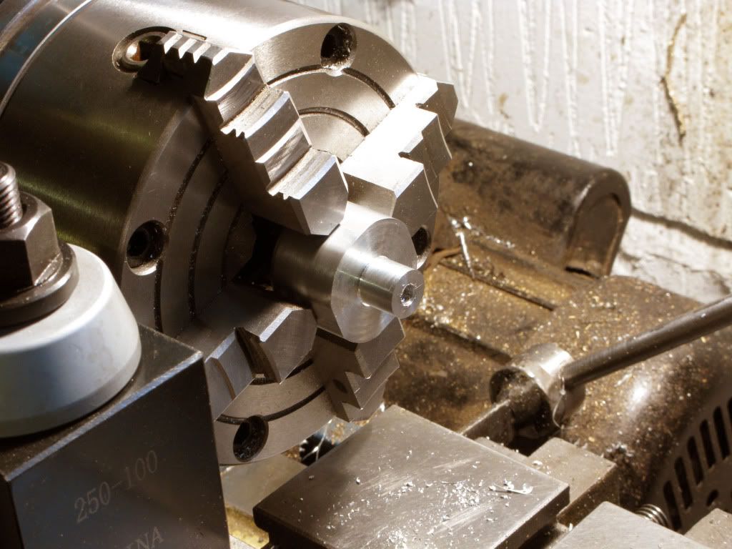
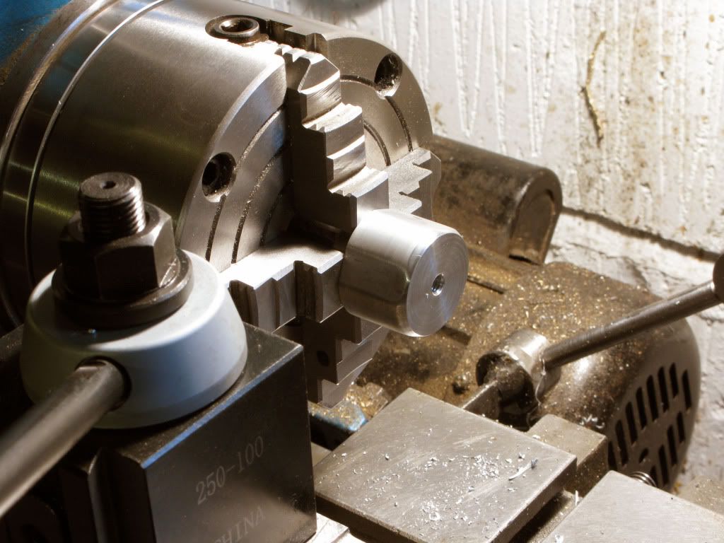
Replacing the 4jaw I centered the col base and turned the 12mm dowel that would fit the base-plate, and drilled a 5mm hole about 15mm deep. Tapping it 6mm.
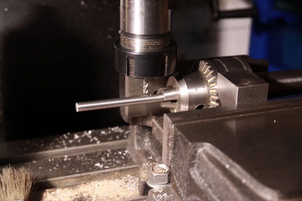
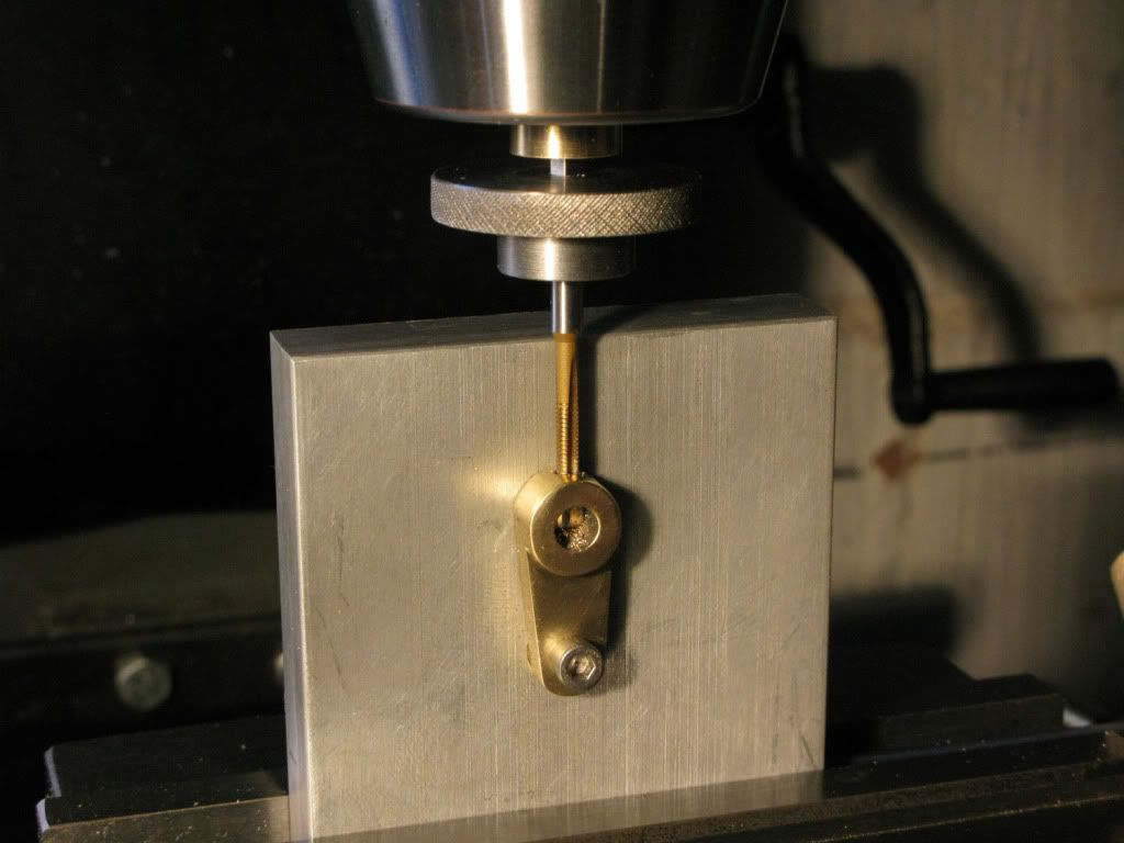
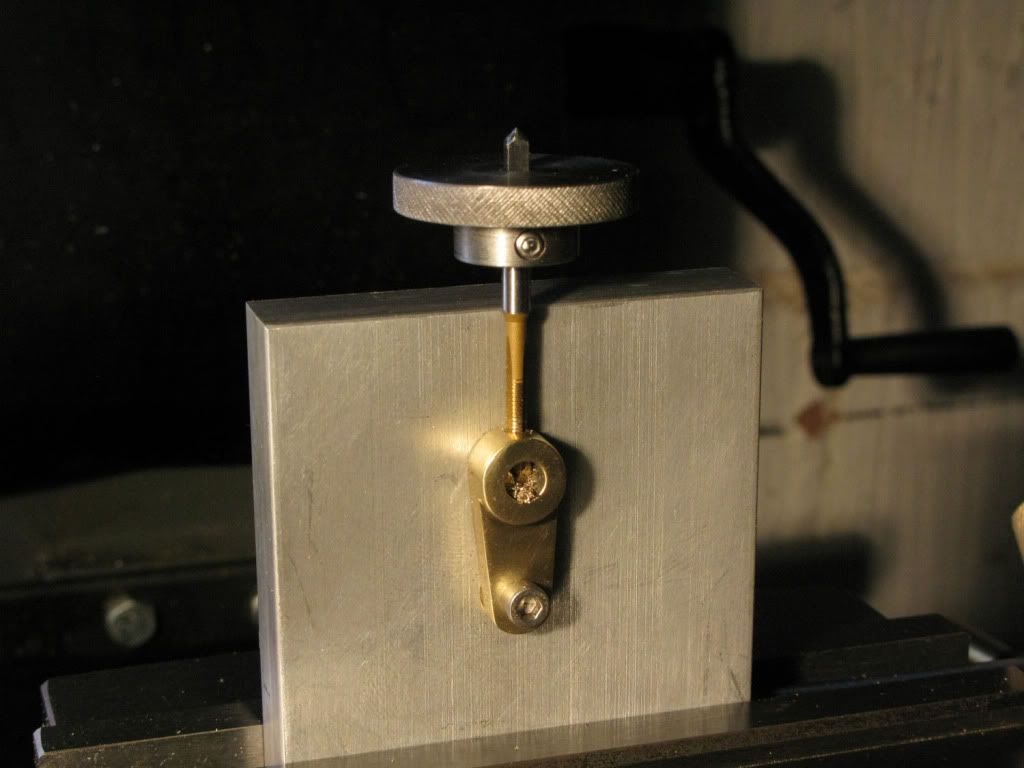
To keep the tap straight I followed a tip I picked up on this forum. Using the business end of an arrow in the chuck, locate point the dimple in the end of the tap and as you wind in the tap, wind the chuck out, this keeps it spot on target. A totally new use for my archery tackle and very effective.
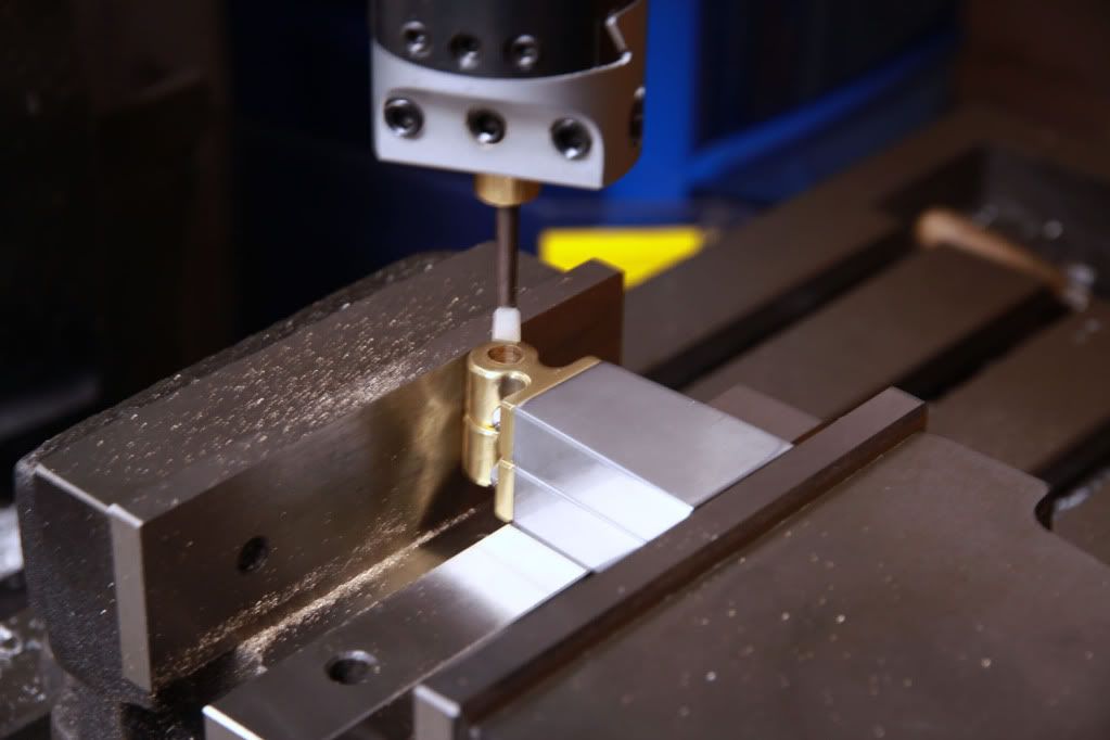
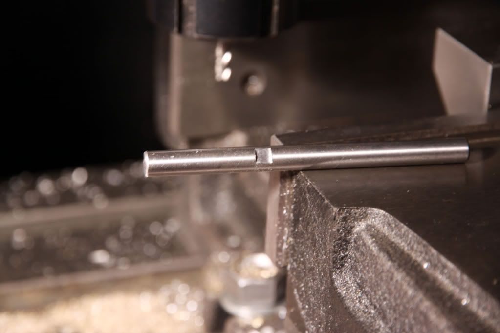
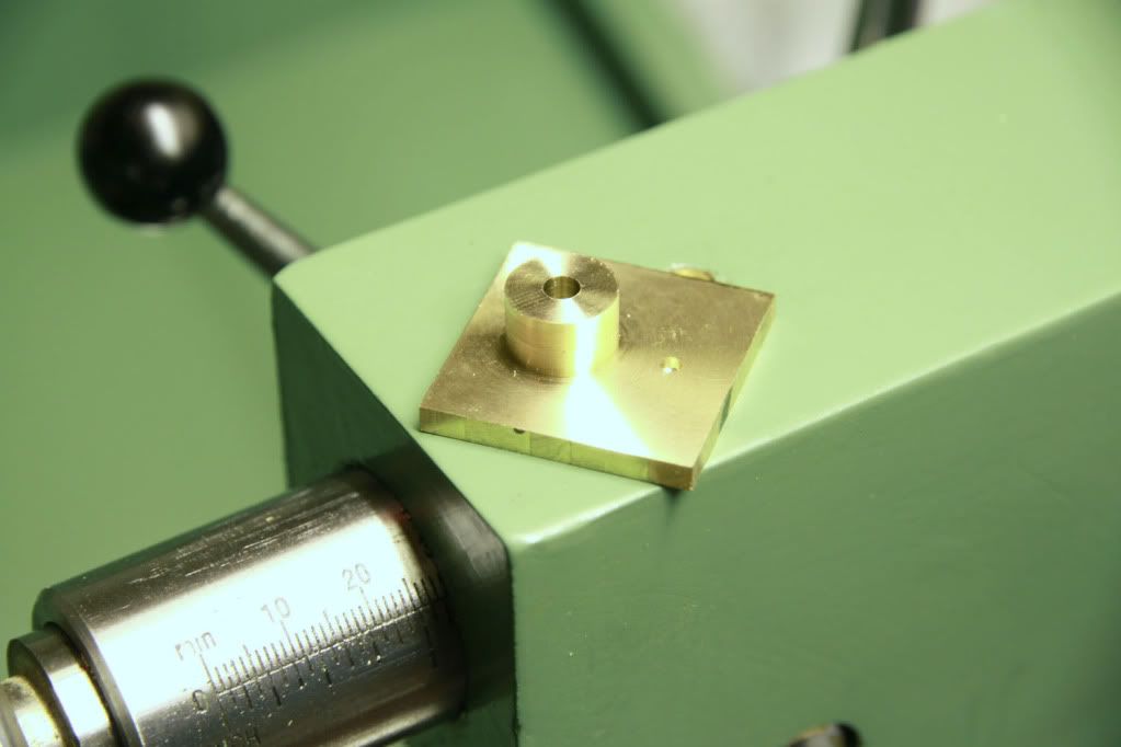
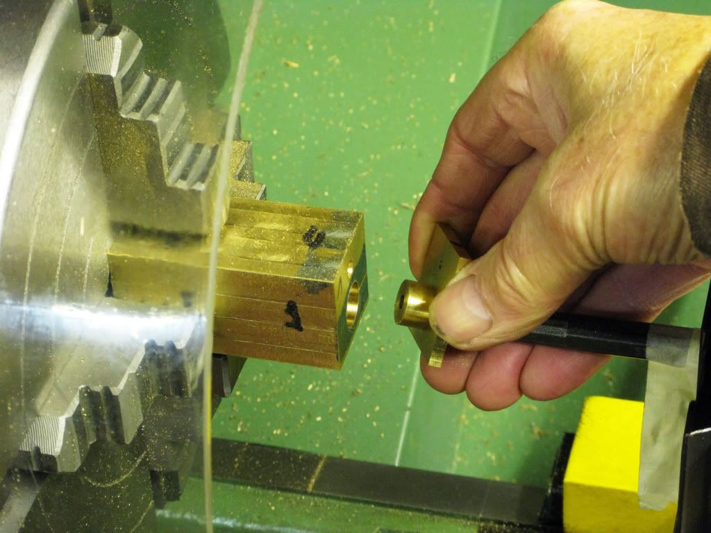
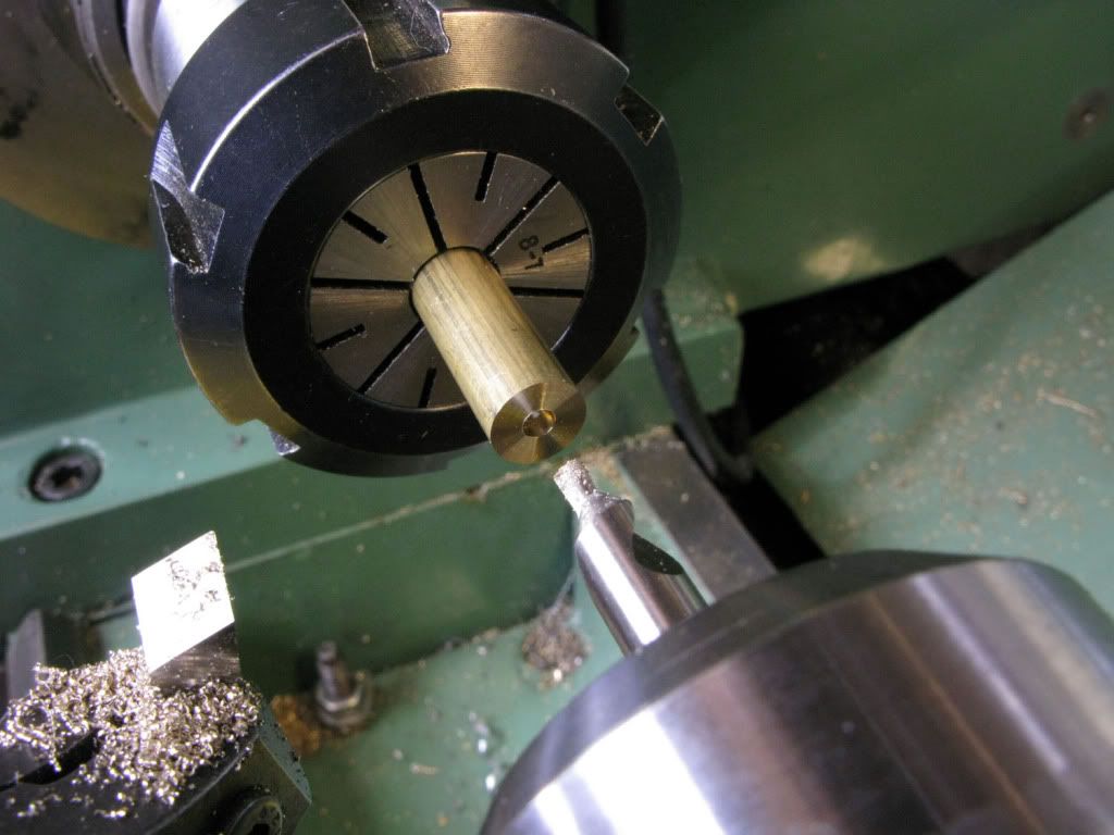
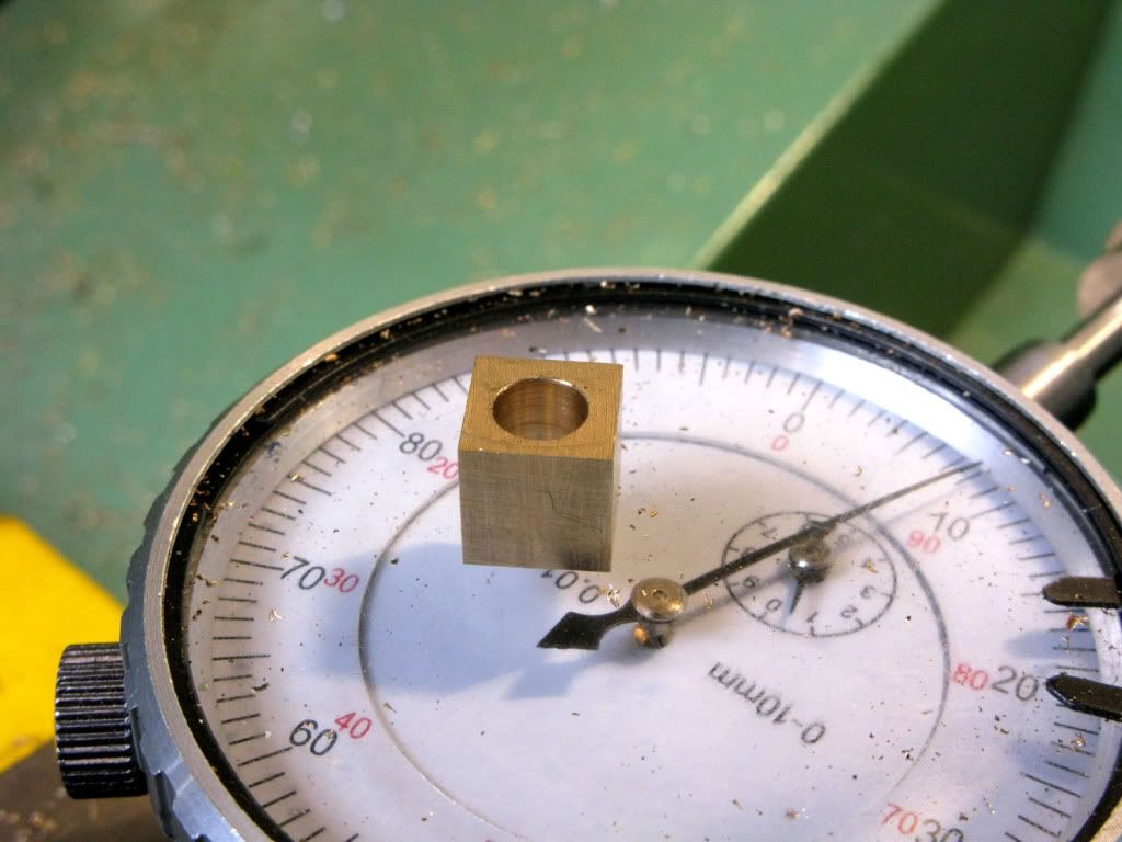
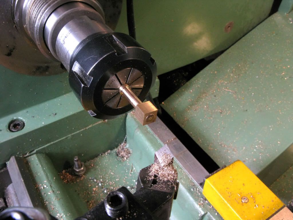
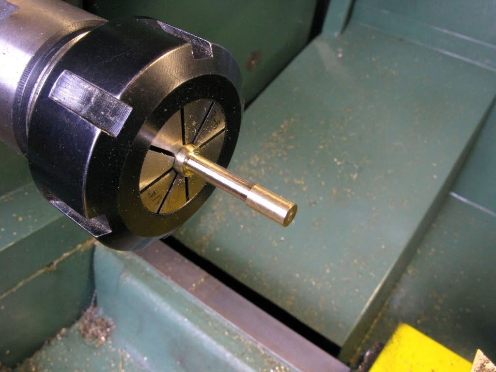
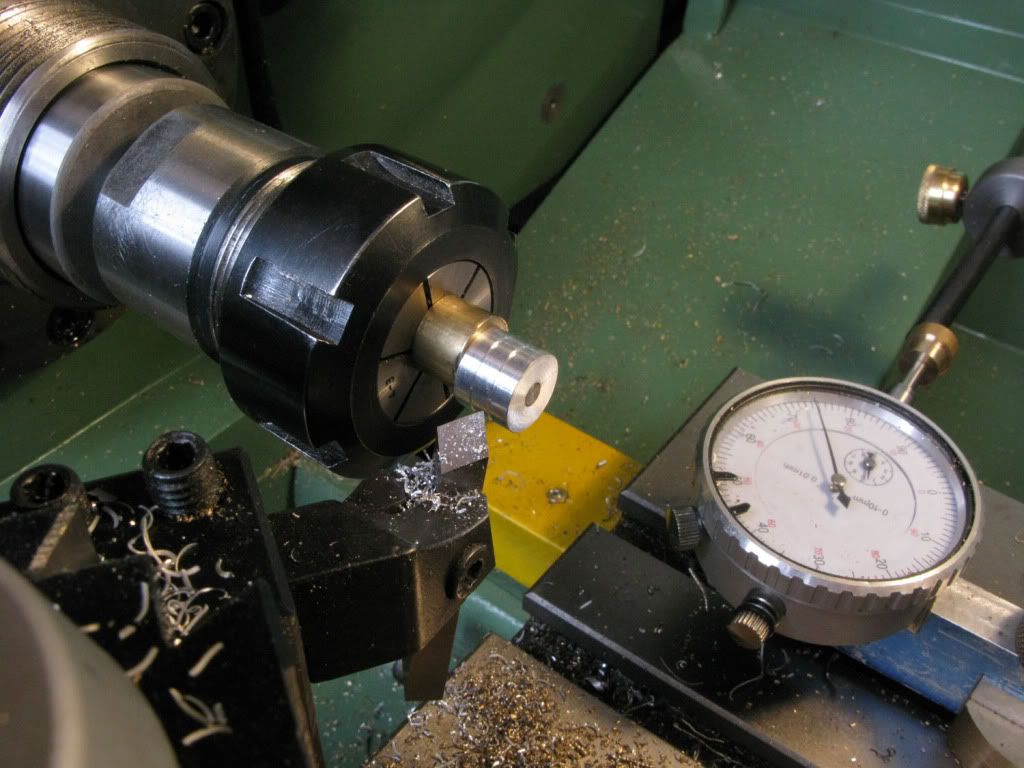
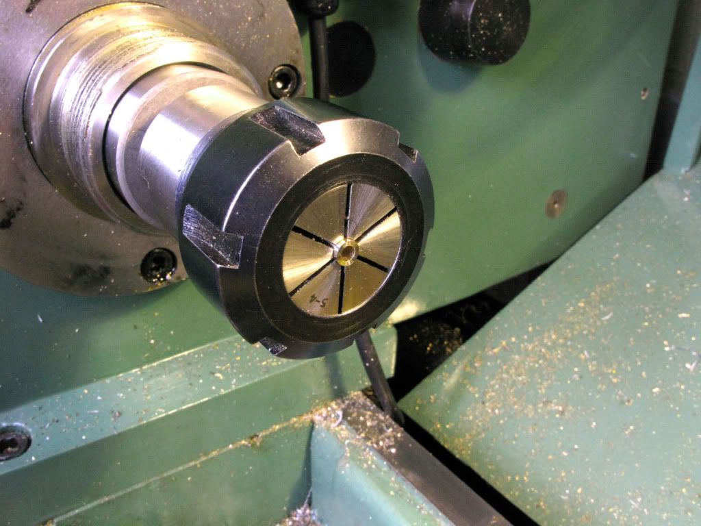
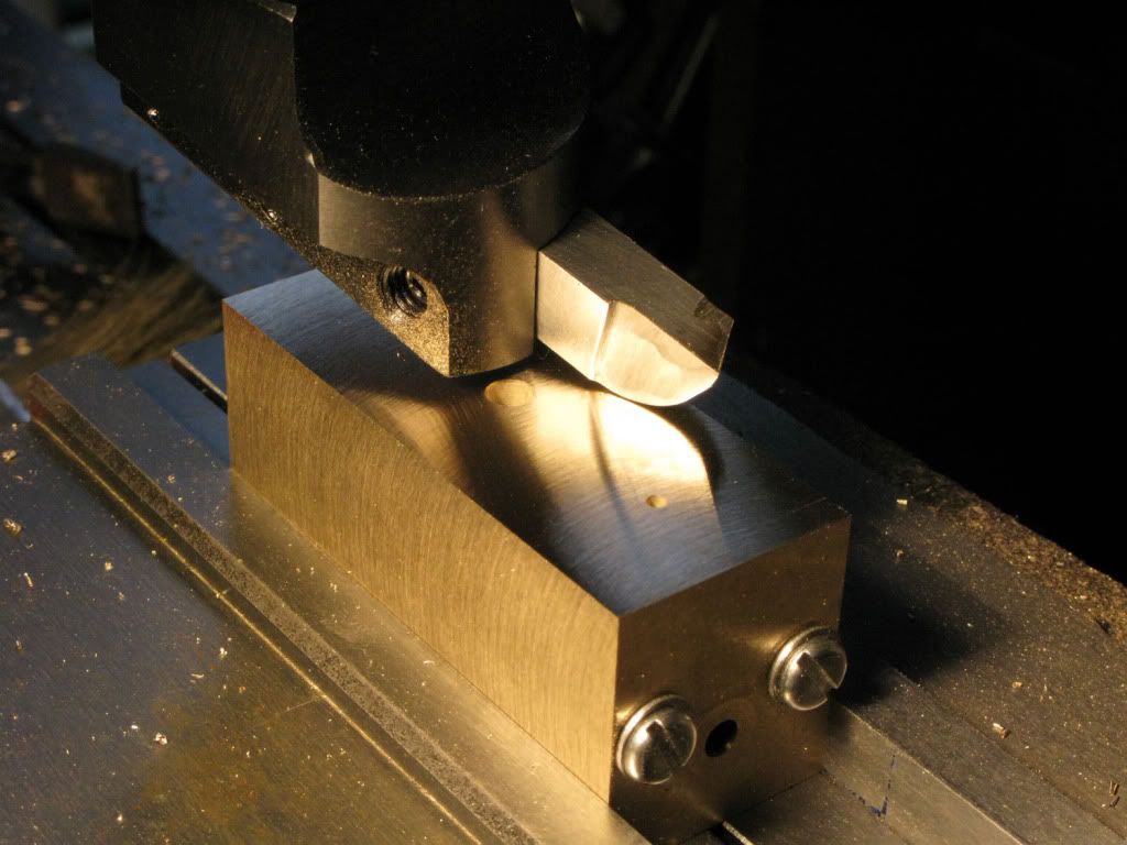
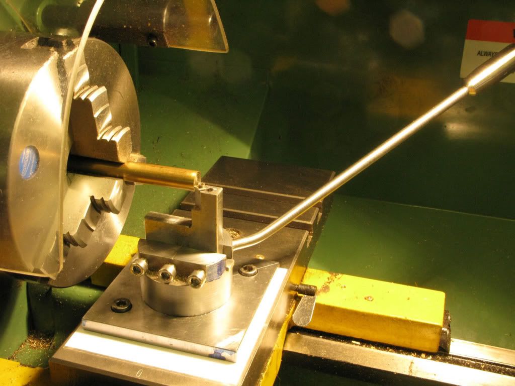
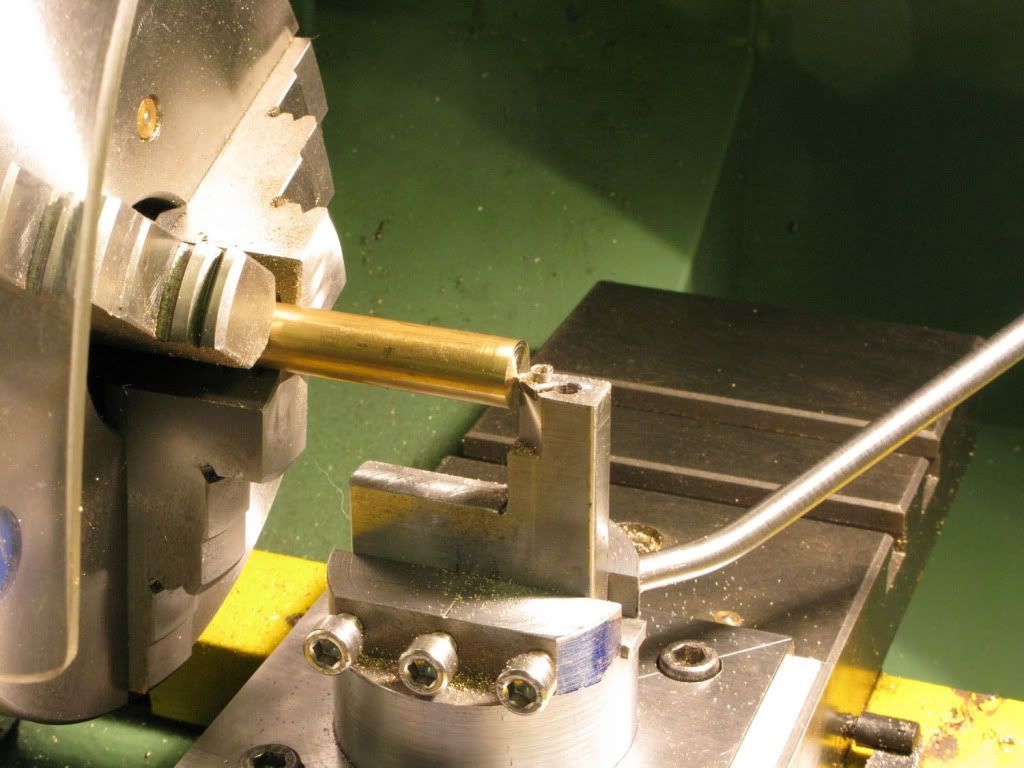
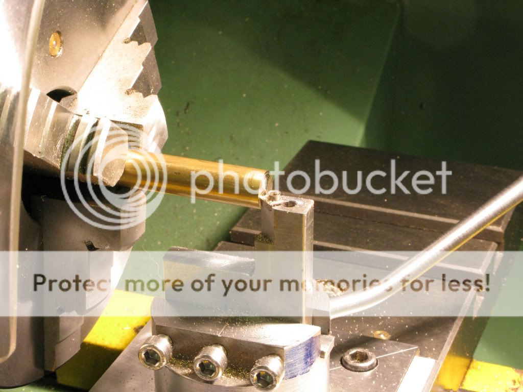
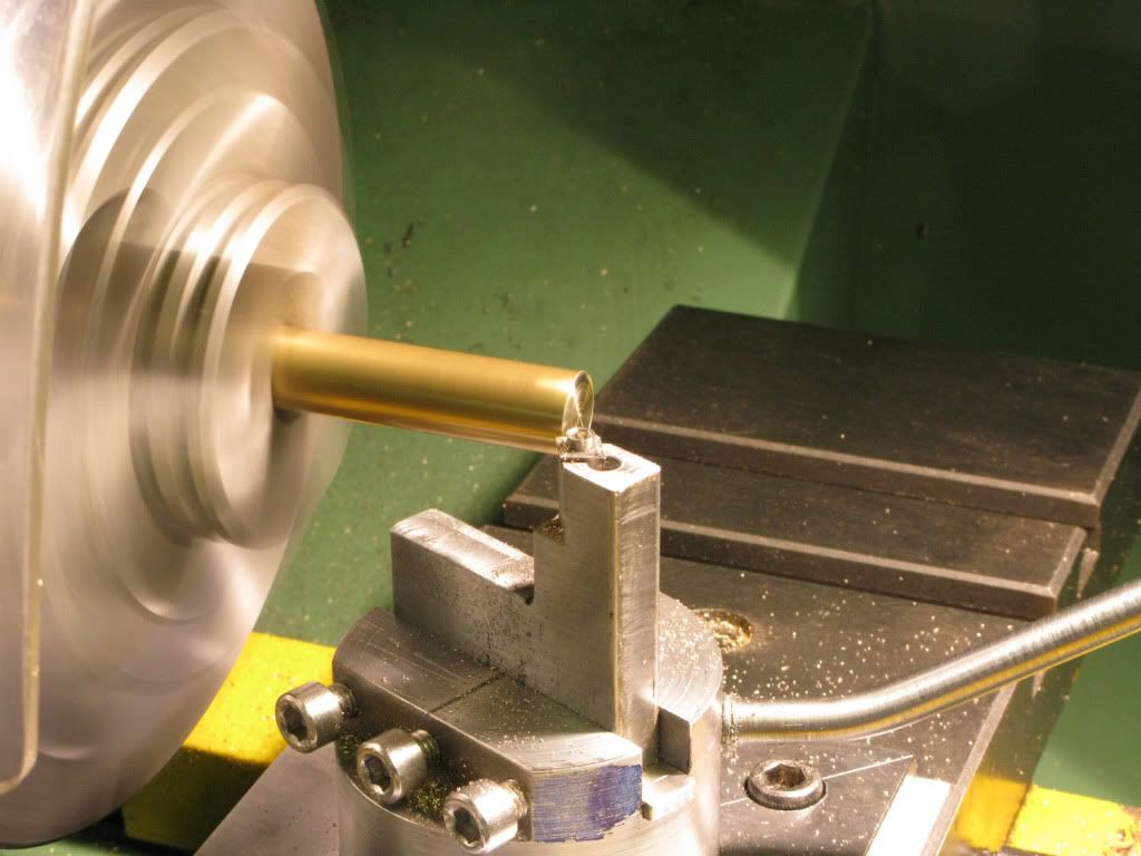
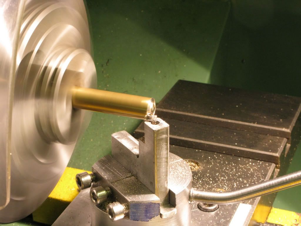
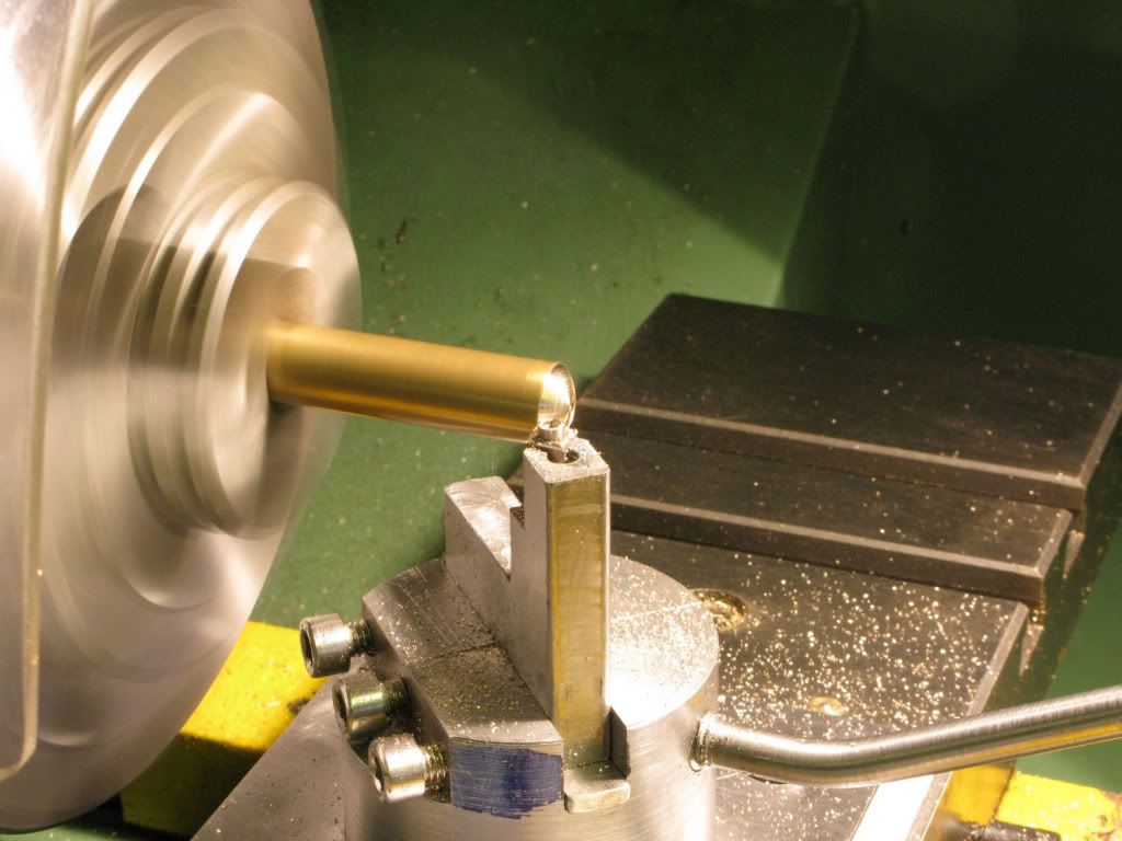
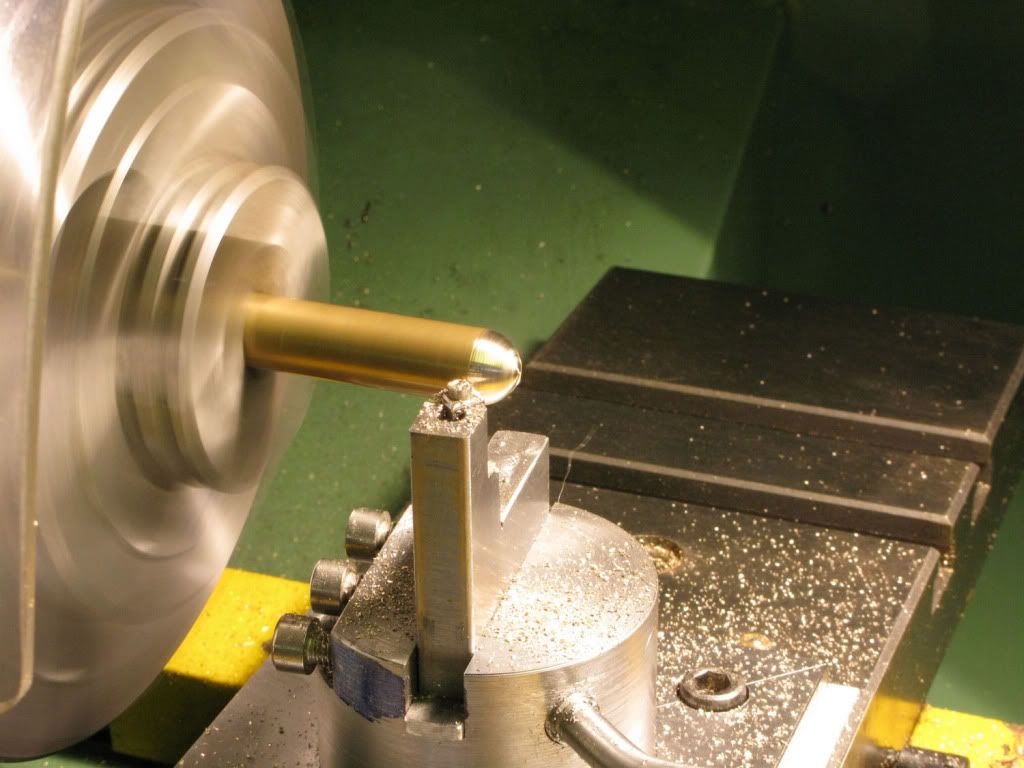
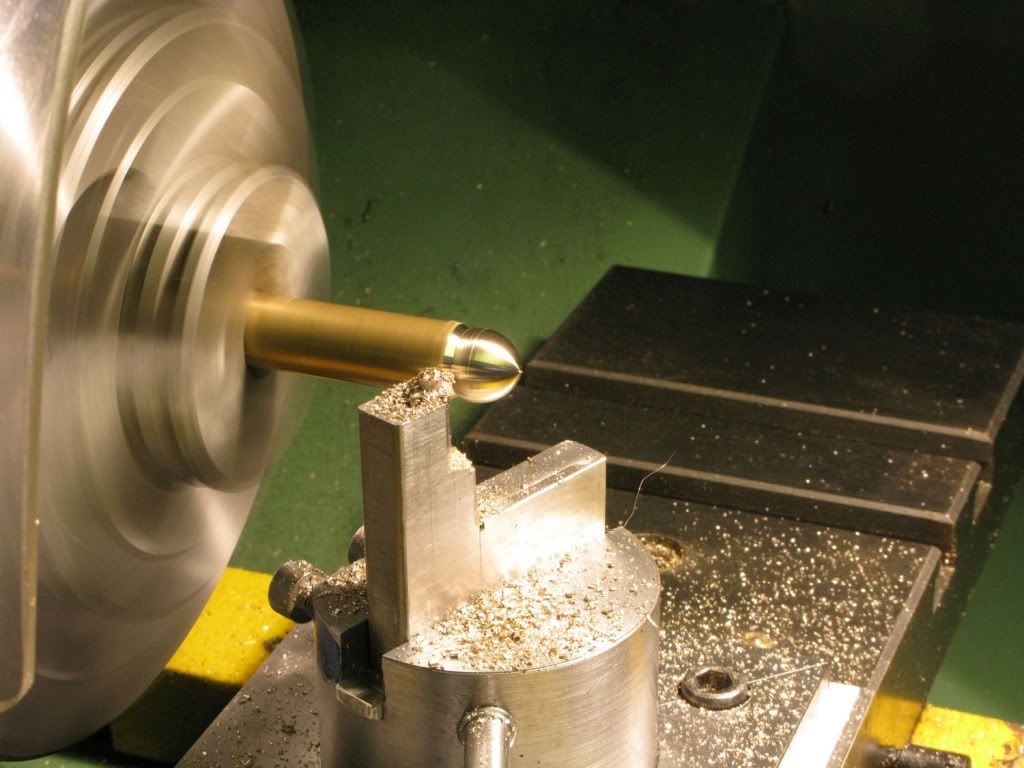
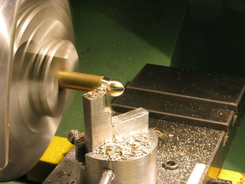
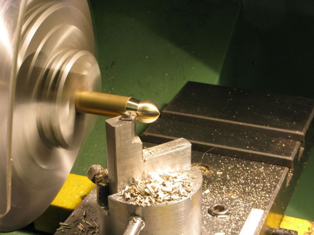
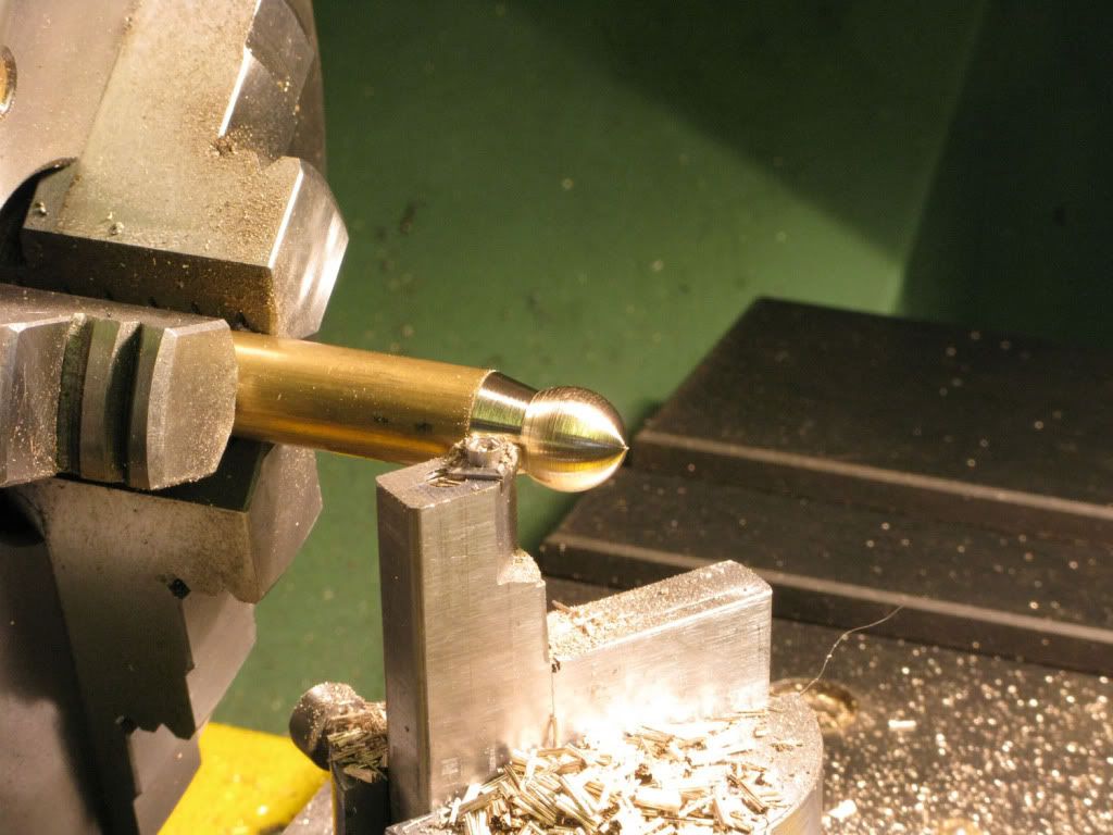
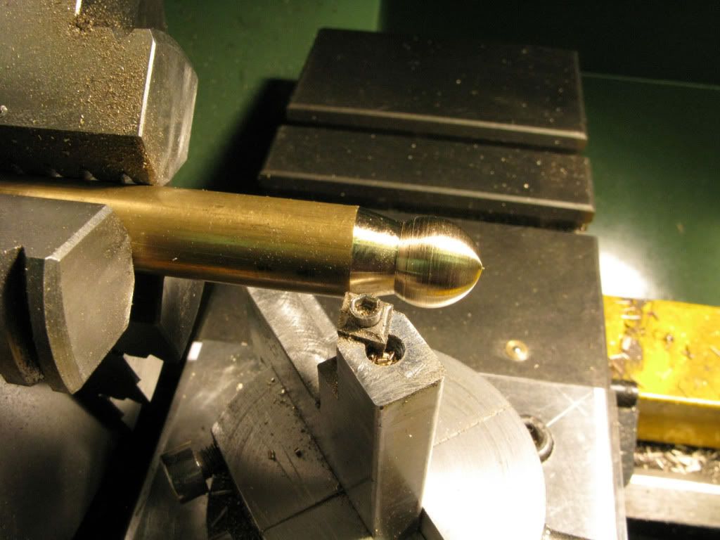
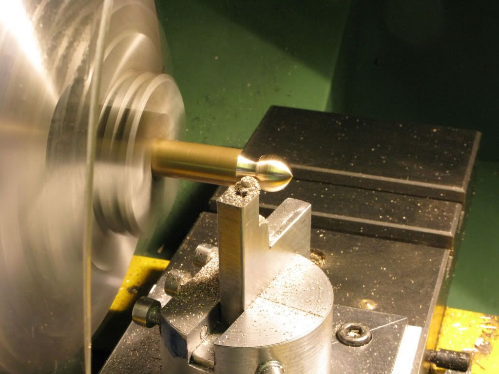
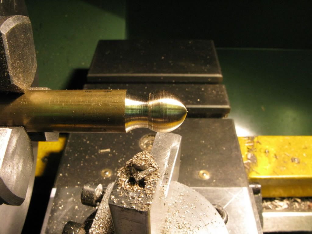
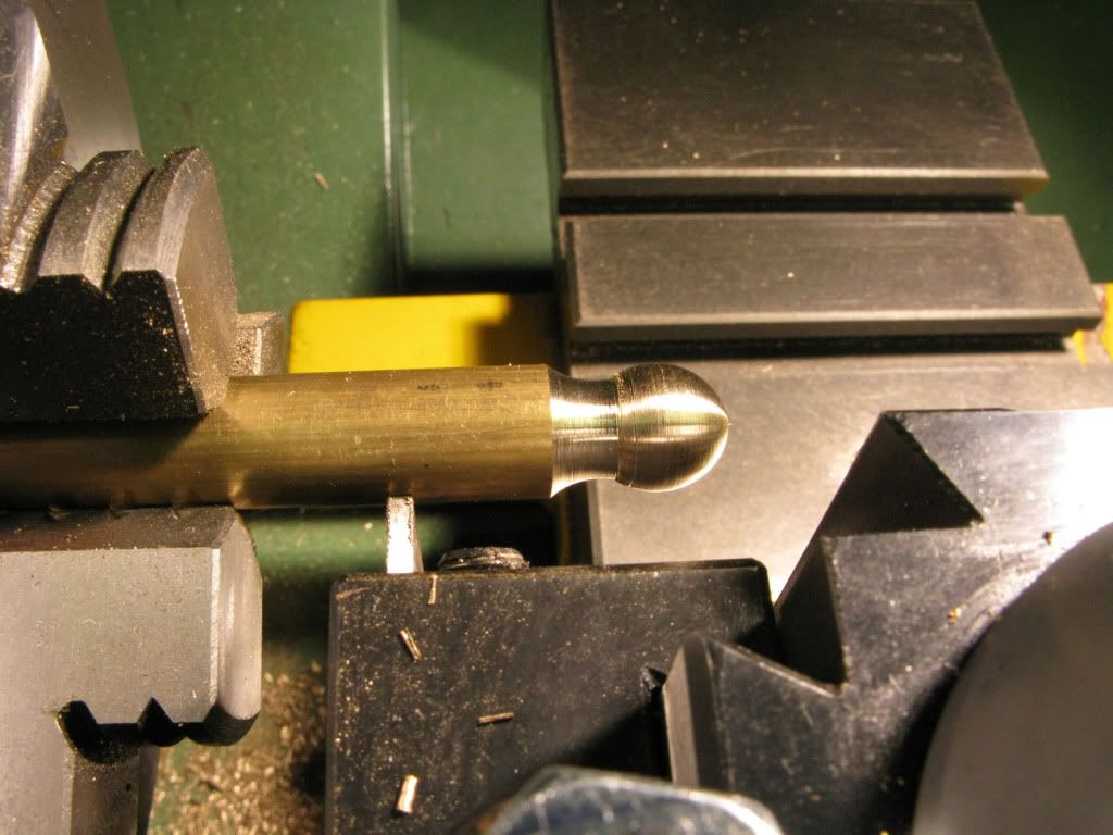
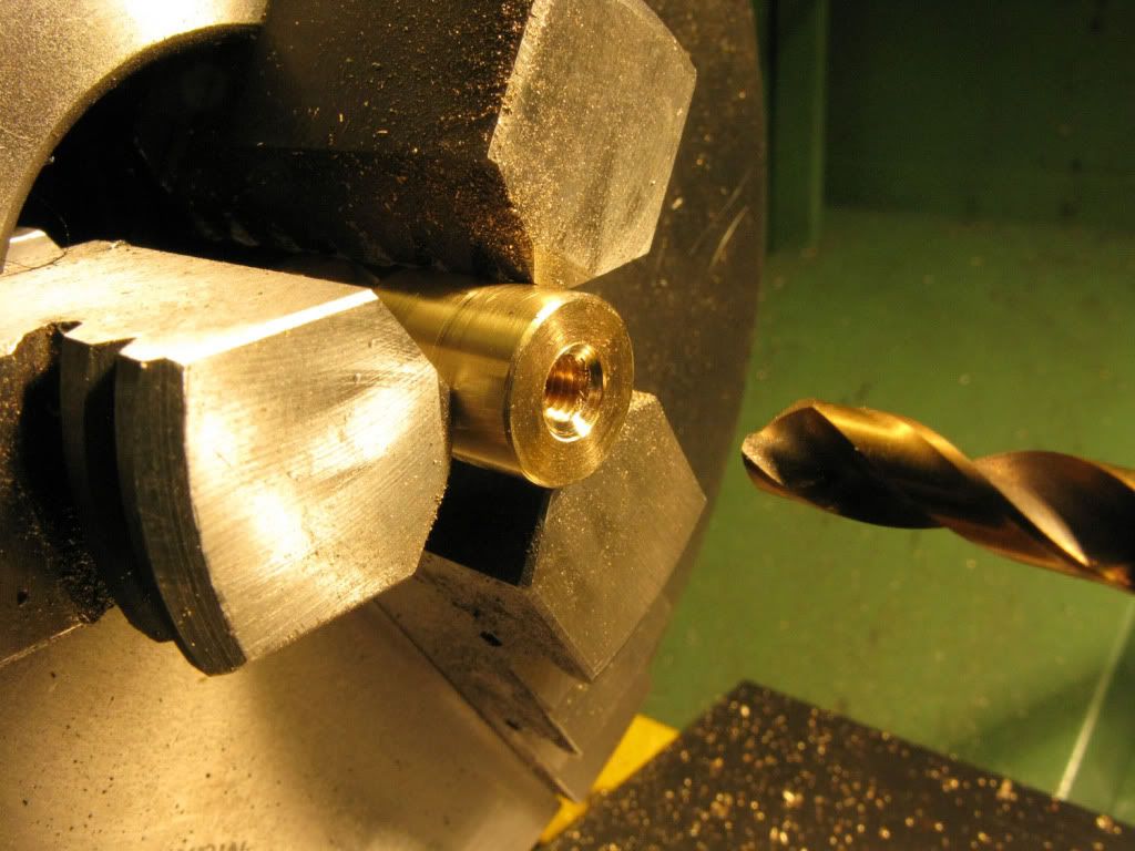
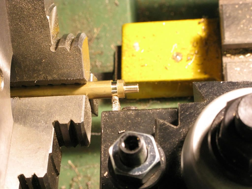
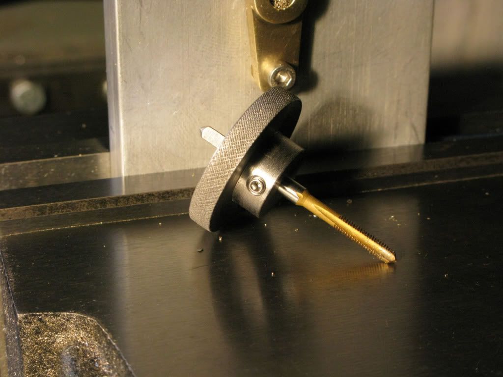
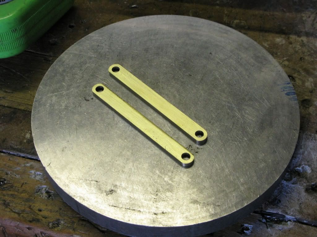
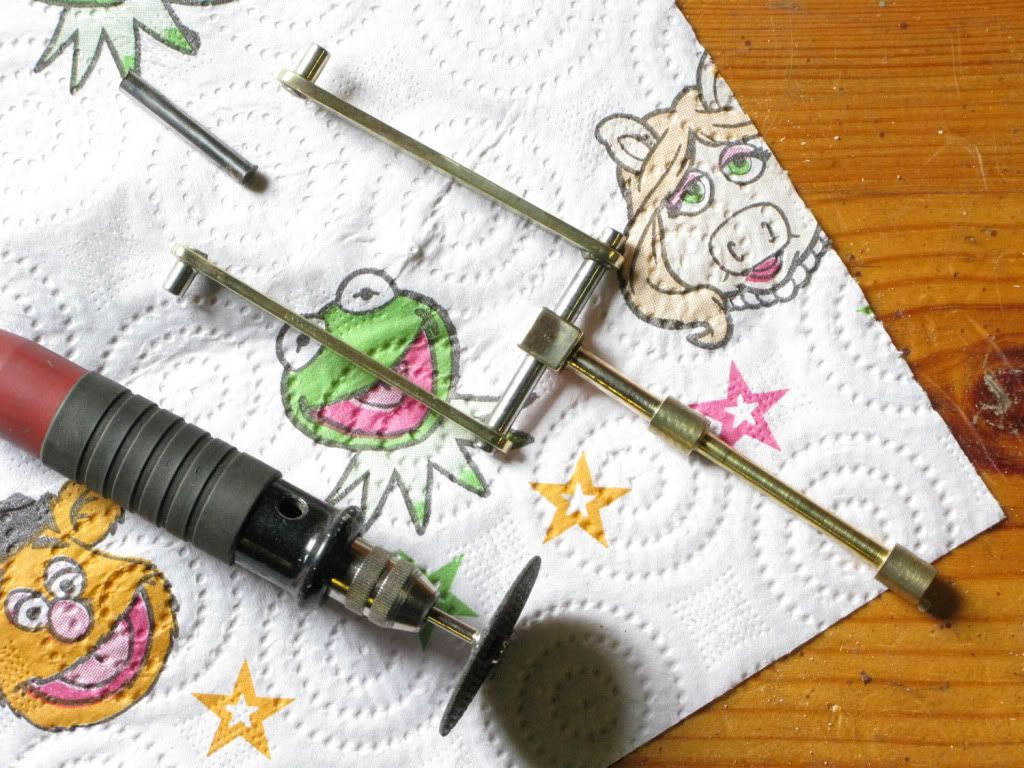
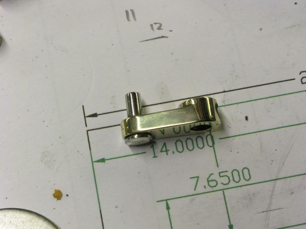
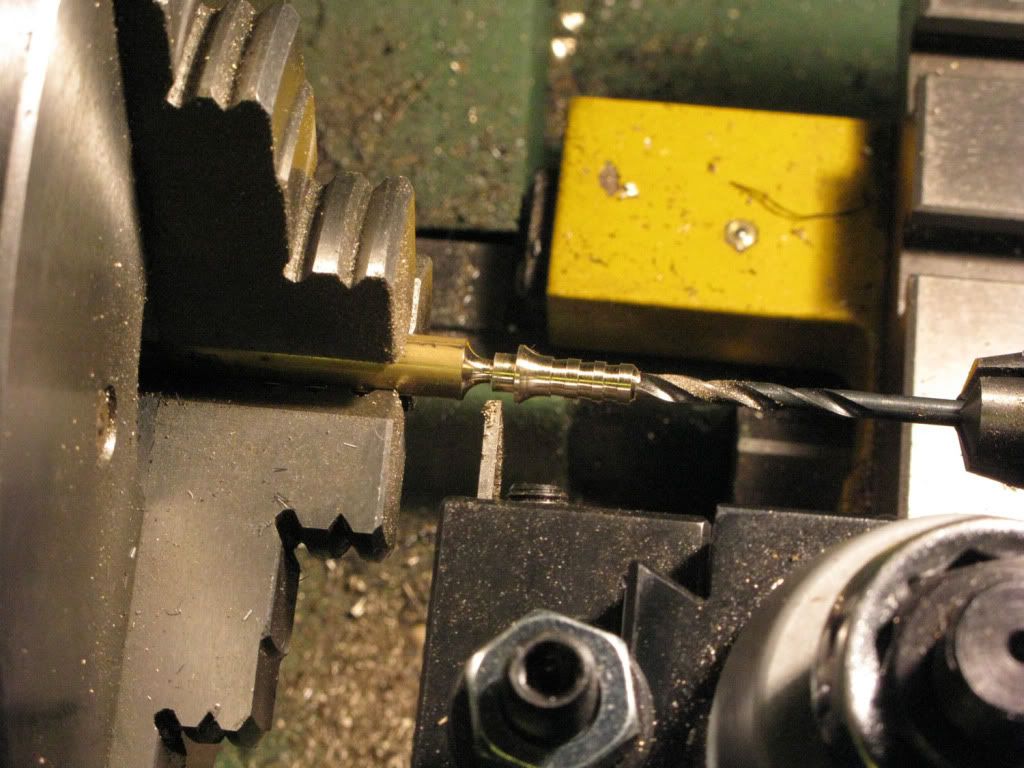
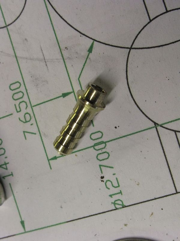
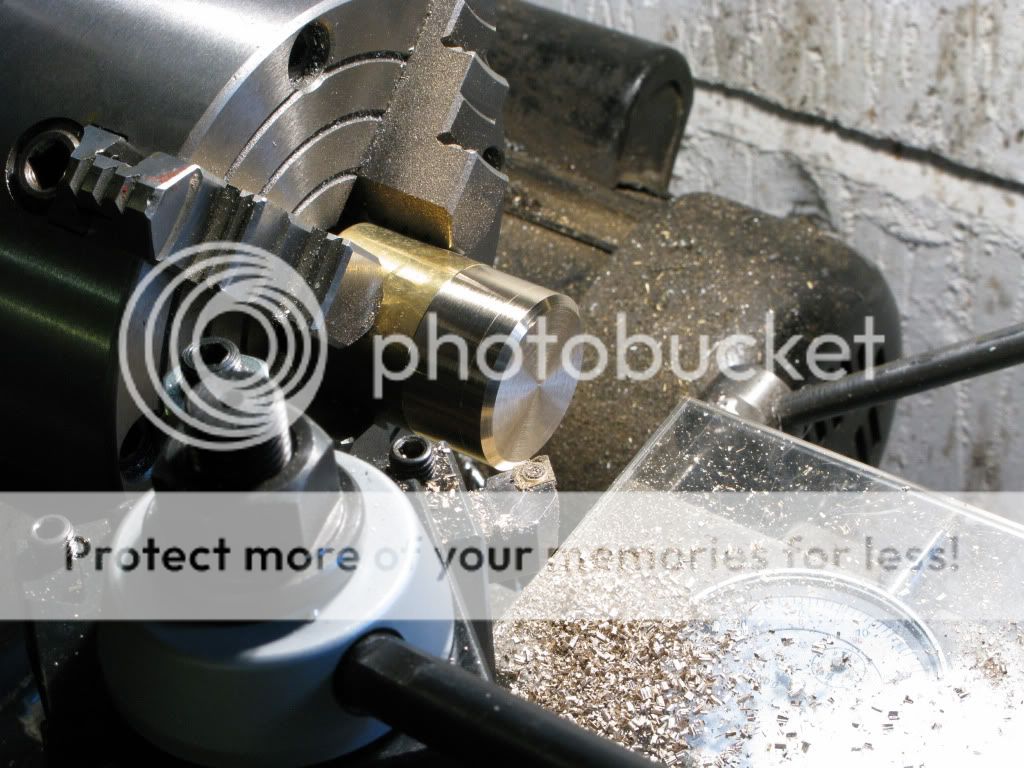
Next I wanted to try Marvs 4jaw setup on round stock so I put in some brass rod to turn the 6mm thick brass sections of the column. As Marve states, with a dedicated DI and two keys, setting up is a breeze, and they were both done and parted off before I even thought of pictures, so I took a mockup of the start chamfer. Both edges have a complete radius, Two chamfers and a lick with a file completes them.
Having still not finalized how I was going to progress the tapered column I swapped back to the three jaw and finished off the col base, giving the end a chamfer and tapping a 6mm hole.
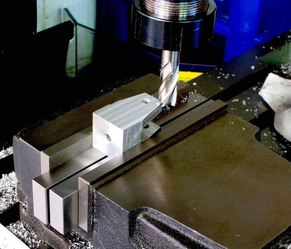
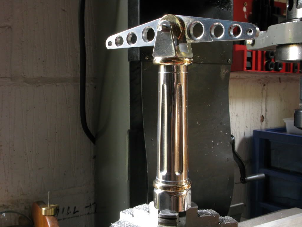
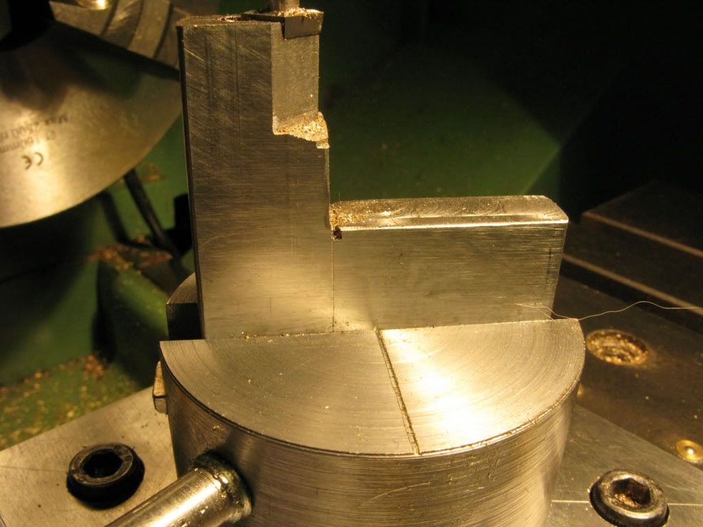
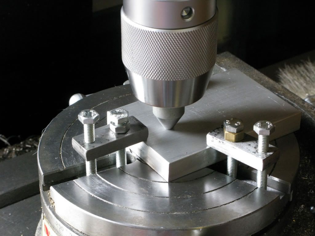
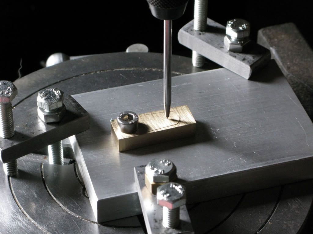
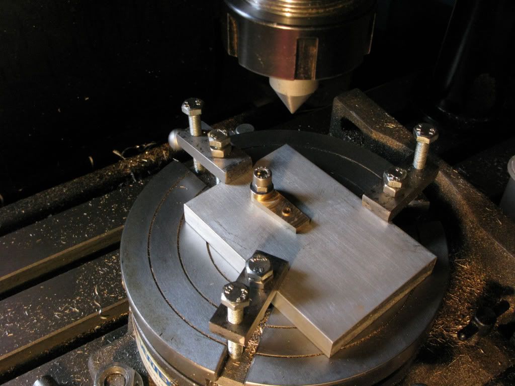
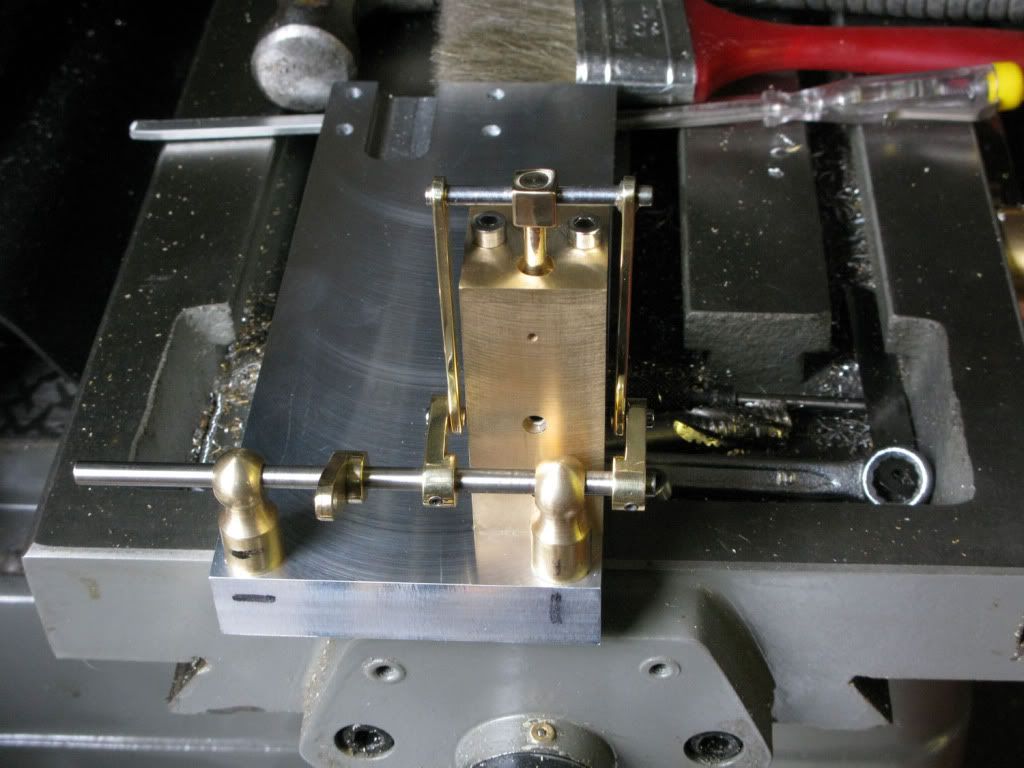
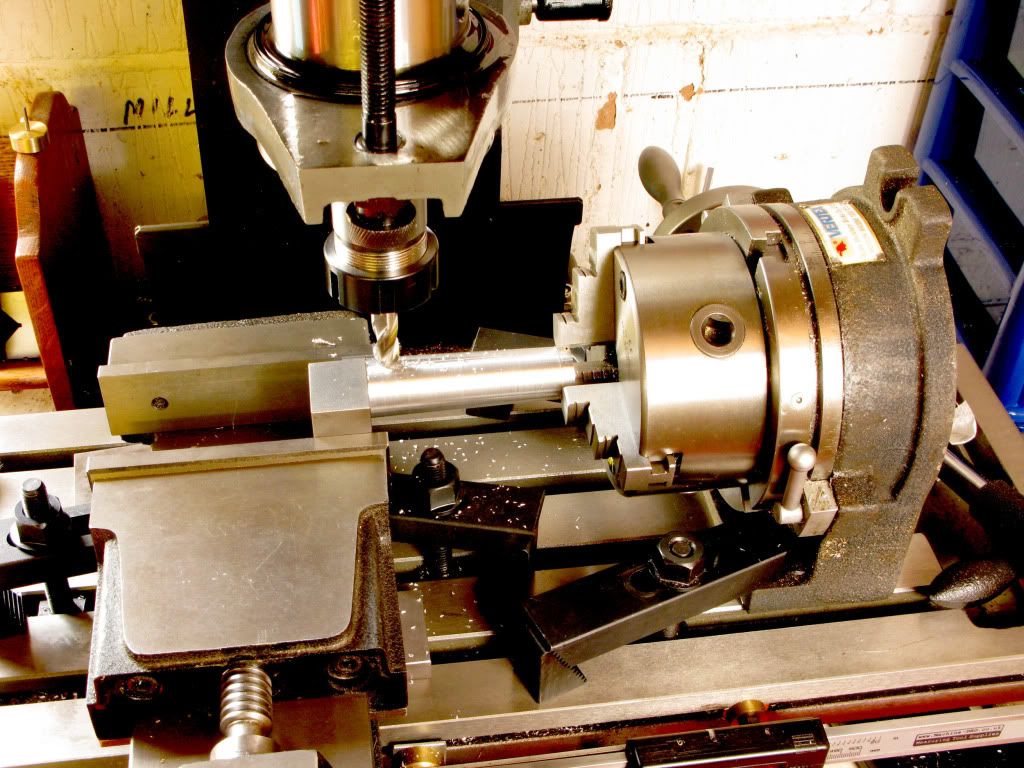
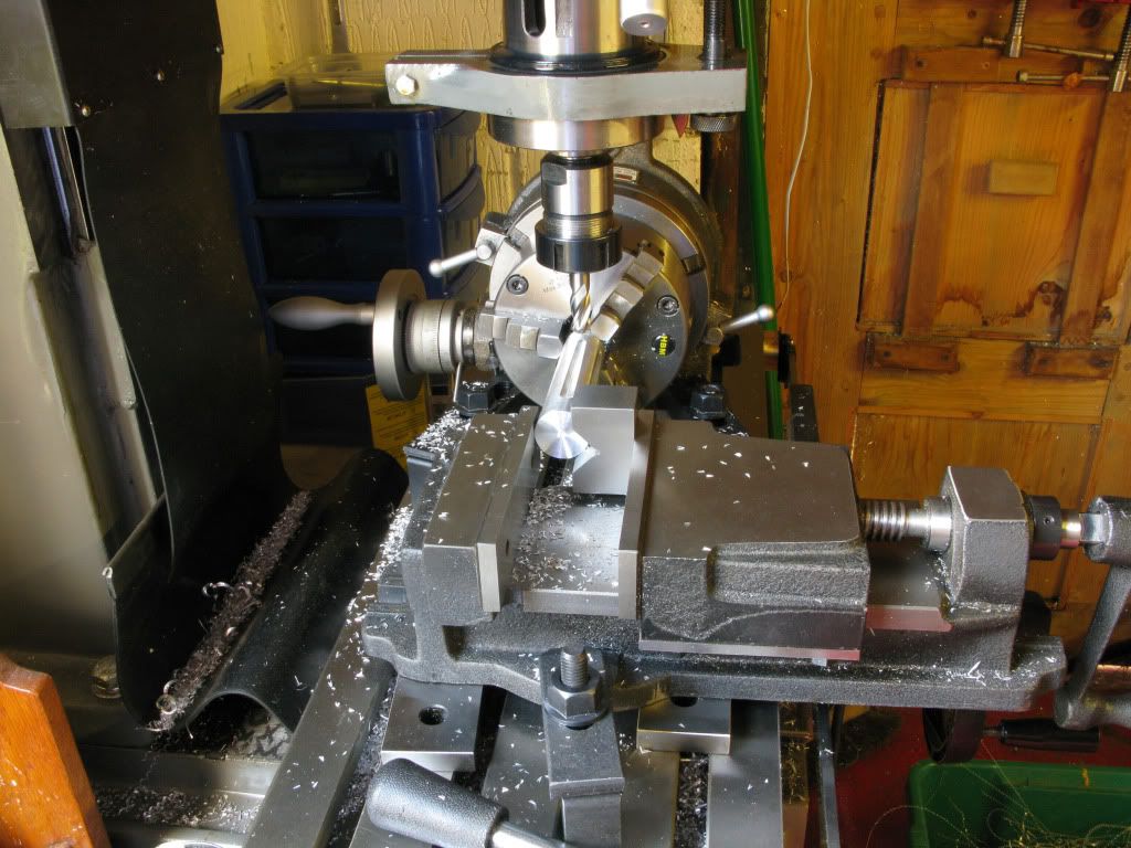
Now for the biggie. Back to the mill. I do have a rotab but no tailstock, Options, set to and make one, wait and buy one or improvise. The last one won.
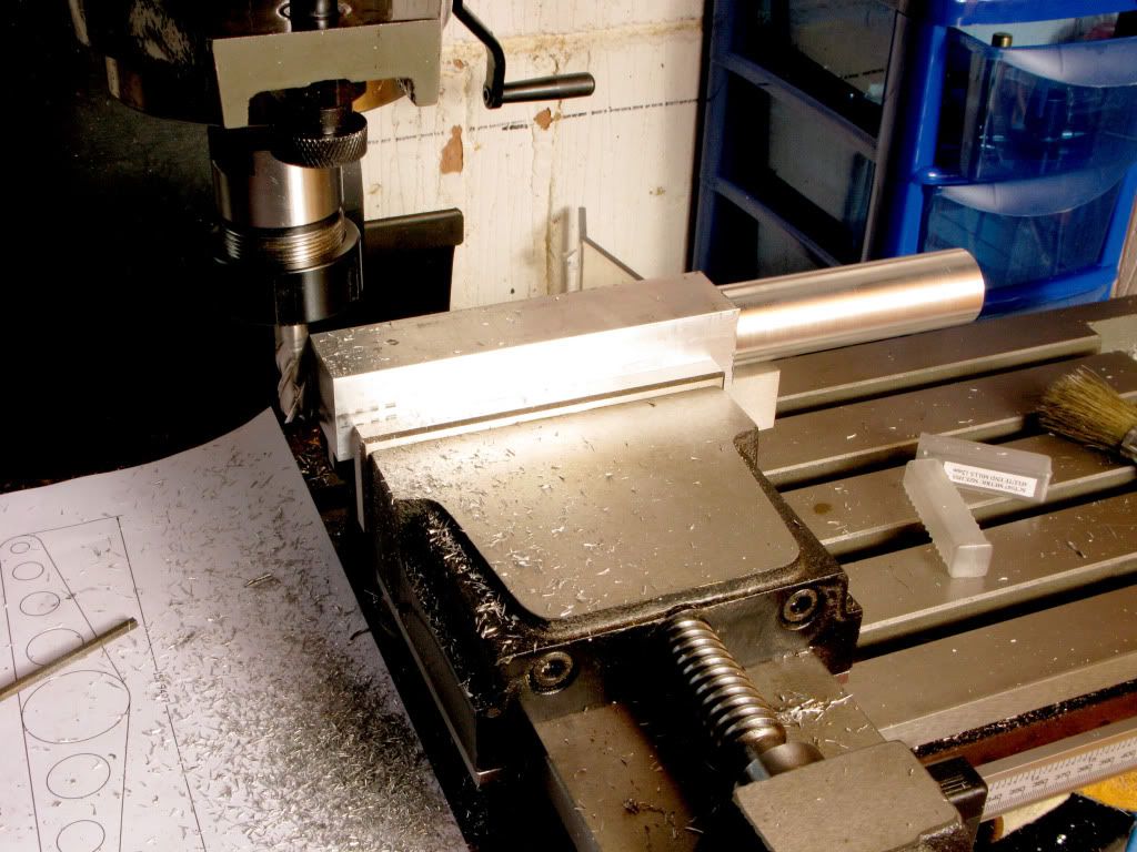
My problem was that whilst I could hold the taper in the chuck mounted on my rotab, thanks to the 10mm parallels I had left each end. I also needed to firmly hold the other end. The solution I arrived at was to mount the rotab in a position where I could hold the other end of the piece in my vice using a vee block, that would also mean having to sit it on parallels to give it sufficient height.
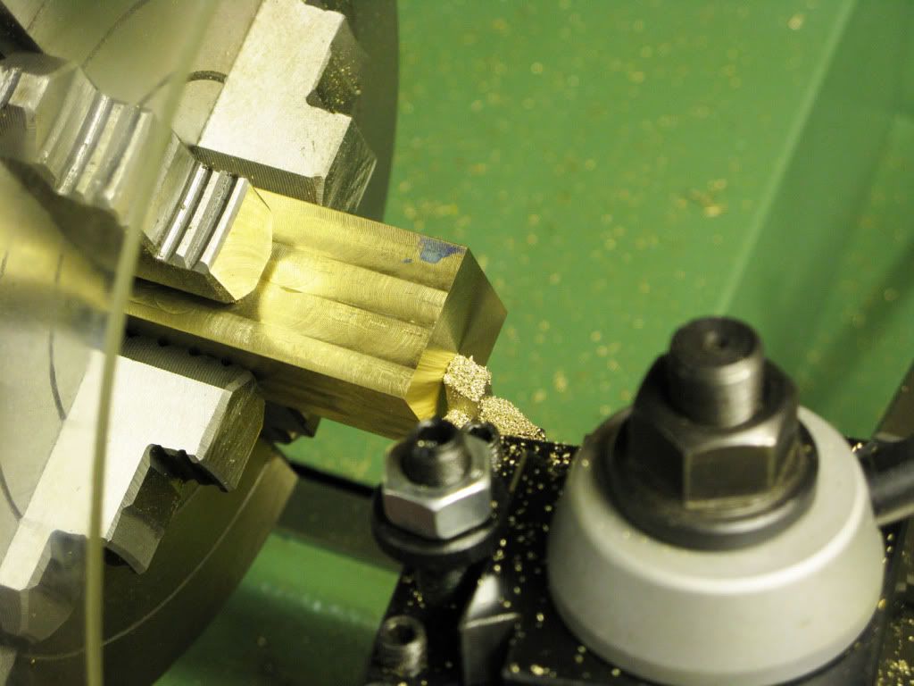
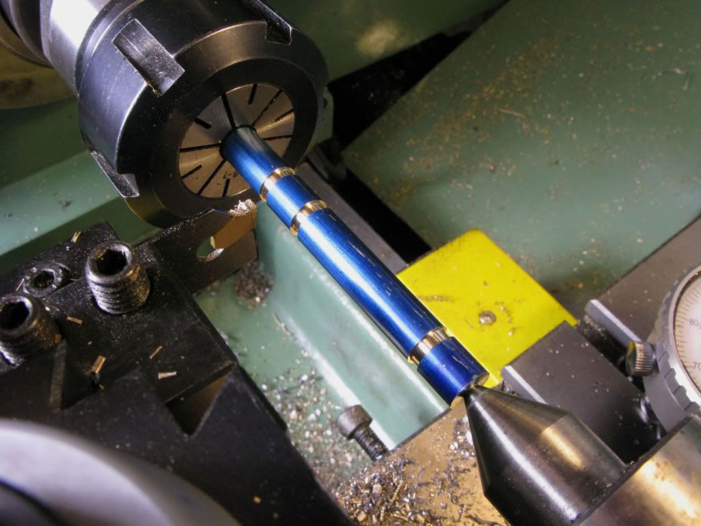
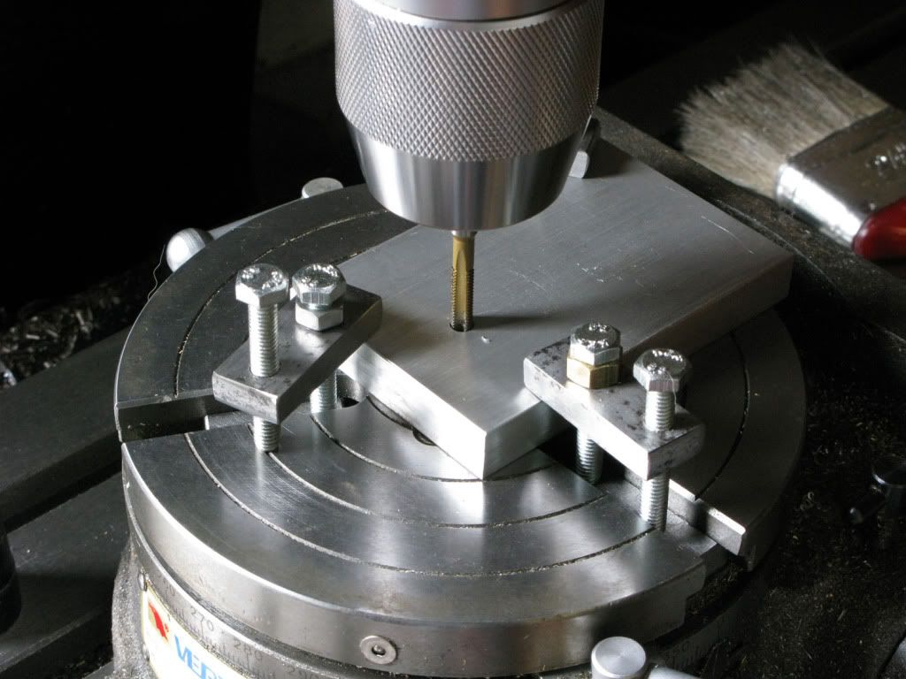
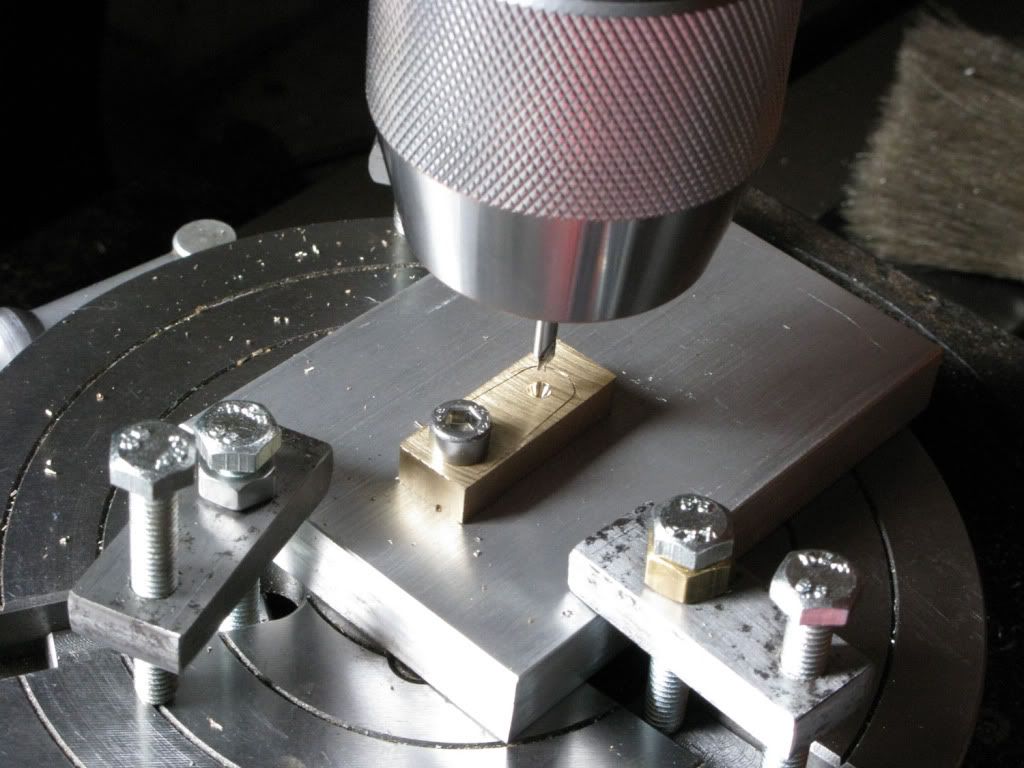
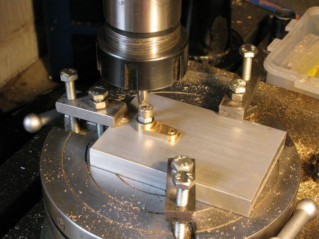
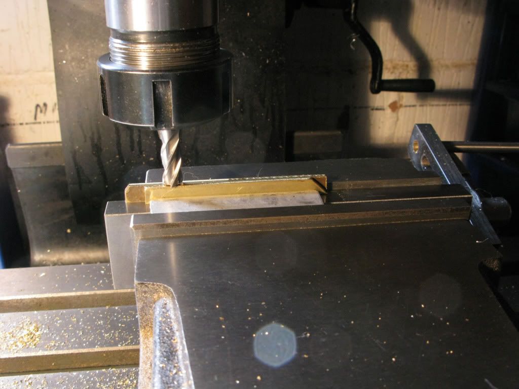
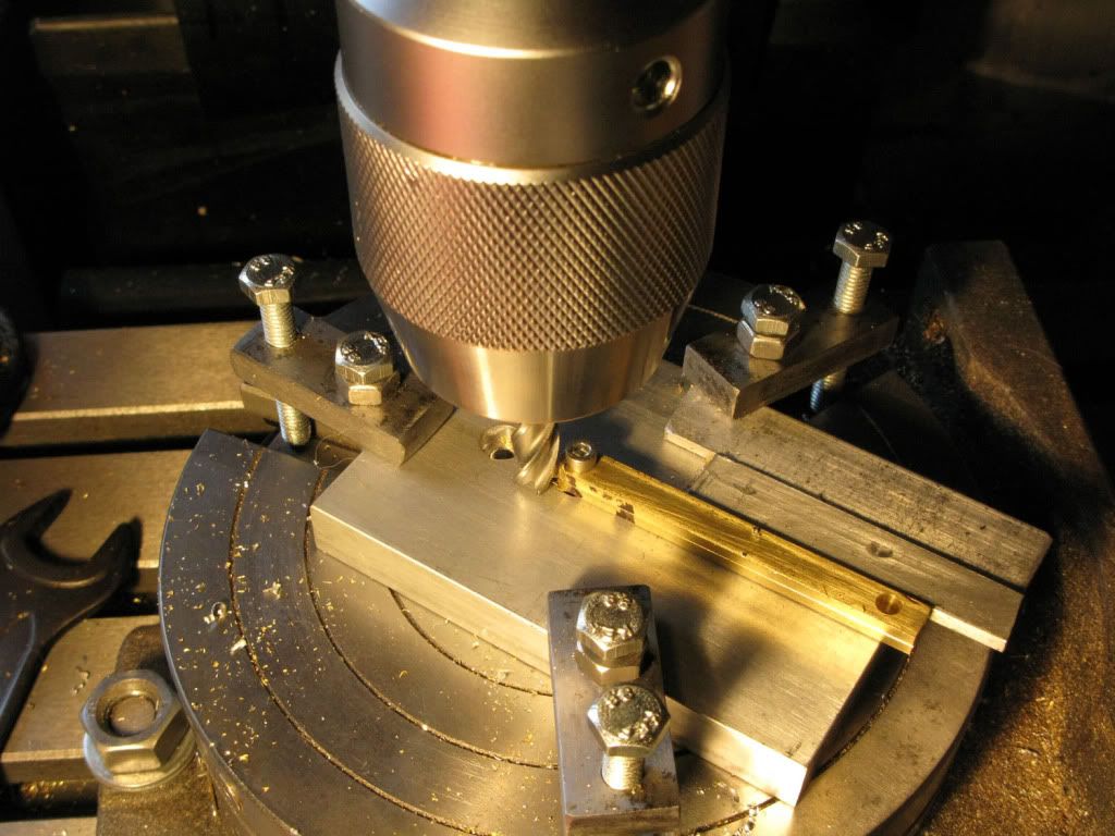
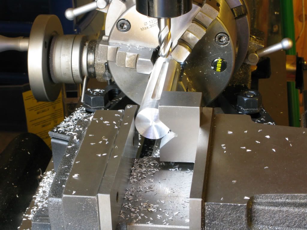
The resultant positioning meant that none of the holding down points coincided with the table slots, so I had to use clamps to secure everything. From then on it went like clockwork. 1 Zero rotab, 2. pinch vice, 3. mill slot with 12mm Bull nose end-mill, 4. loosen vice wind rotab 60 degrees, 5. pinch vice. And so on until rotab was back to zero. Increase the Z depth and start all over again. Keep going until the slots look right. Hang a sign in front of your eyes saying. DONT FORGET TO TIGHTEN/LOOSEN THE VICE
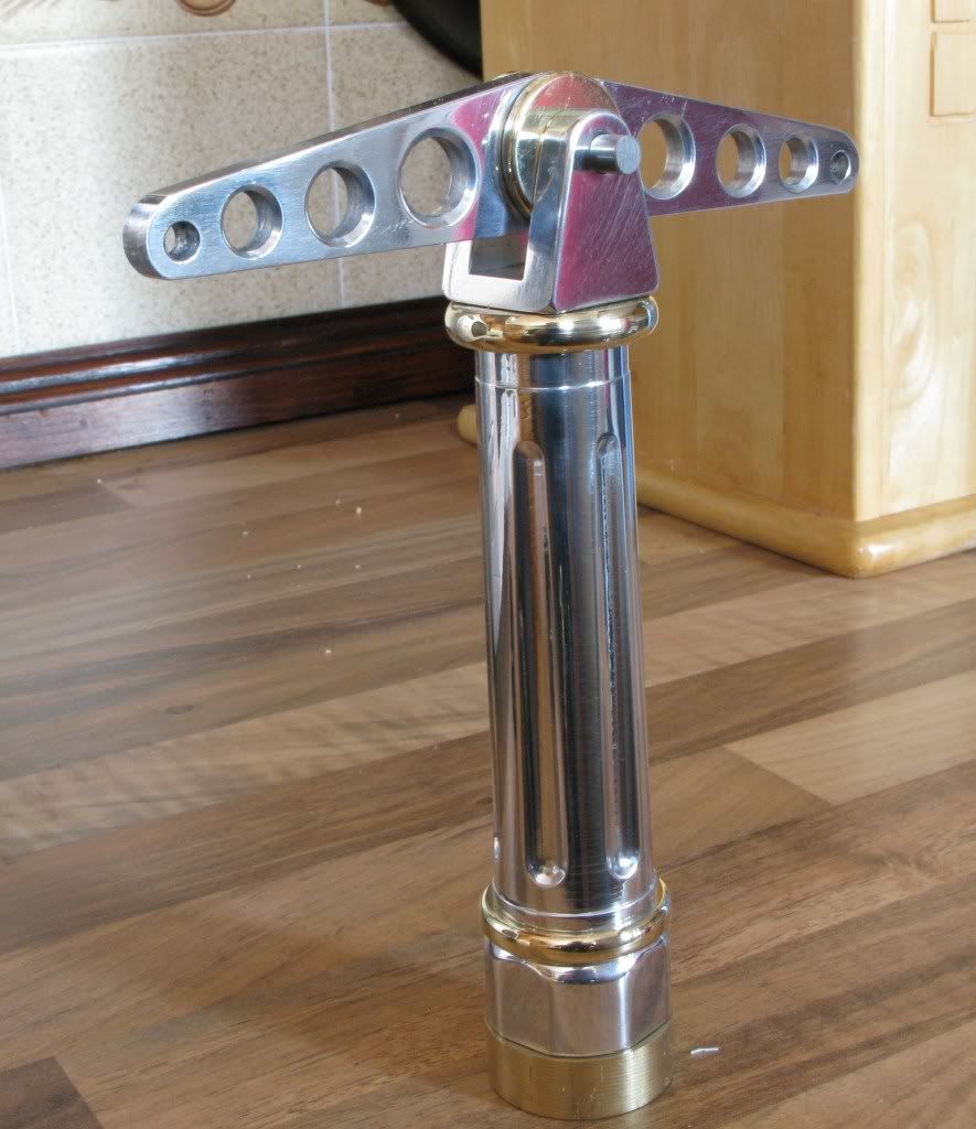
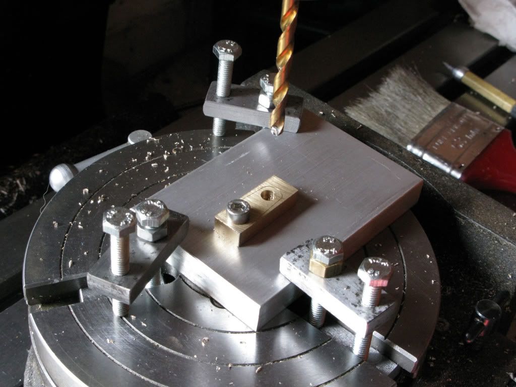
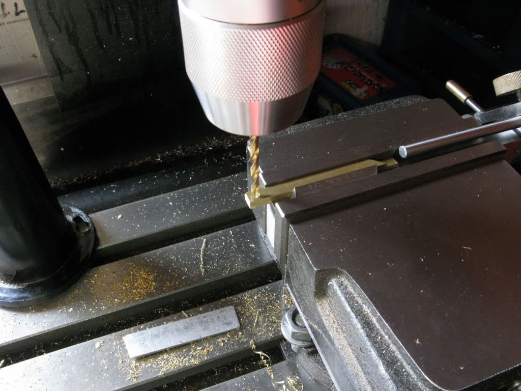
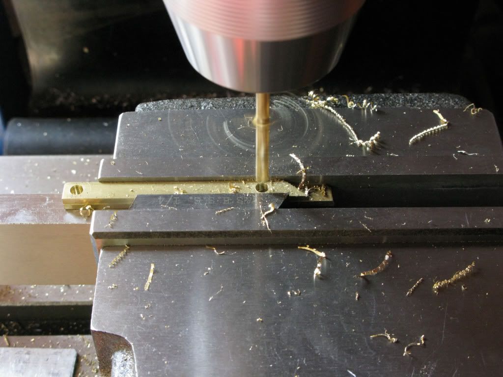
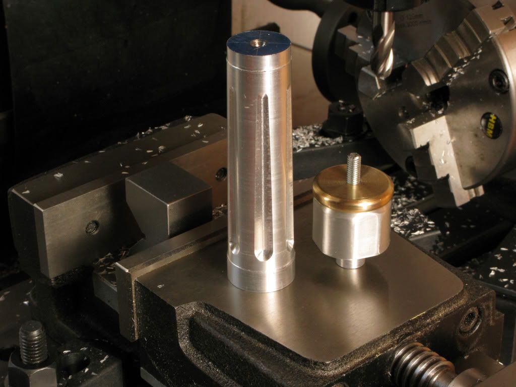
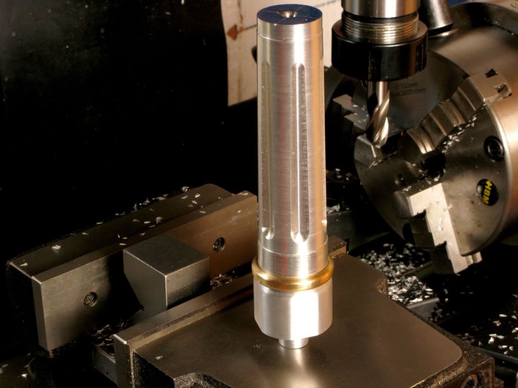
The finishing touch was to put in the lathe and using 400 W&D give it a final polish, then drill and tap the 6mm holes each end, back in the mill, then marry it up with the col base and brass section.
To do this I thought I would make it in several parts, because if I screw up the tapered section which is a strong possibility, then I only have to remake it, or redesign it to a simpler format, also I will simplify the addition of some brass.
Starting with a more than sufficient length of 32mm square ally I faced one end in the mill, marked the centre and drilled it for the tailstock. I then put the new 4 jaw on the lathe. It was at this point that I realized that Marvs 4jaw setup tutorial described the setup for rounds, so I pondered the problem for a while, then thought about the tiny spirit level I had in my toolbox.
This fit nicely on the flats of the jaws enabling me to get each jaw horizontal, as I followed Marvs instructions moving the level to the opposite jaw as each DI comparison and adjustment was made. Eventually I managed to get the piece centered.
You are probably chuckling at this Heath Robinson method and know of a much simpler one. PLEASE enlighten me.
I started by turning the piece so that the rounded section was about 3mm larger than the diameter required for the thickest part of the intended taper and 25mm longer
Now for a venture into the unknown. Turning between centers. Did I chop off the round section and taper that, and if so how would I drive it, or should I leave it be and use the square as a means of drive and again how would I drive it.
Finally I went for the safer option, faced the square end and centre drilled it.
I was flapping so much by now that photography didnt even cross my mind. I had set the work between centers and I had no drive dogs. Time to improvise, with an ancient home made brake hydraulic hose clamp, a couple of long 8mm bolts quickly mig-welded together and a turn of stainless steel tying to tie the bolt to the clamp.
Mockup picture below for your amusement.
I worked out that I needed to offset the tailstock just over 4.5mm to get the desired taper but from time to time the &(*&% thing chattered like a chimp at a tea party, finally I wound the live centre in really hard which cured the problem, and I was able to make the subsequent and final cuts nice and clean.
Is it something I was doing wrong, did I center-drill the holes too deep or what. The previous parallel turning using the same tool was perfect ???? Not an encouraging start to taper turning. However the result was just fine. Comments would be welcome.
Before removing from the lathe I backed off the tailstock returned it to its original position and wound the tailstock back in, then turned corners off another section of the square stock so that they were about equal to the width to the flats. This would be the base of the column.
Removing it from the lathe I cut off the taper on which I had left 10mm of parallel section at each end, then cut off the piece for the col base.
Replacing the 4jaw I centered the col base and turned the 12mm dowel that would fit the base-plate, and drilled a 5mm hole about 15mm deep. Tapping it 6mm.
To keep the tap straight I followed a tip I picked up on this forum. Using the business end of an arrow in the chuck, locate point the dimple in the end of the tap and as you wind in the tap, wind the chuck out, this keeps it spot on target. A totally new use for my archery tackle and very effective.
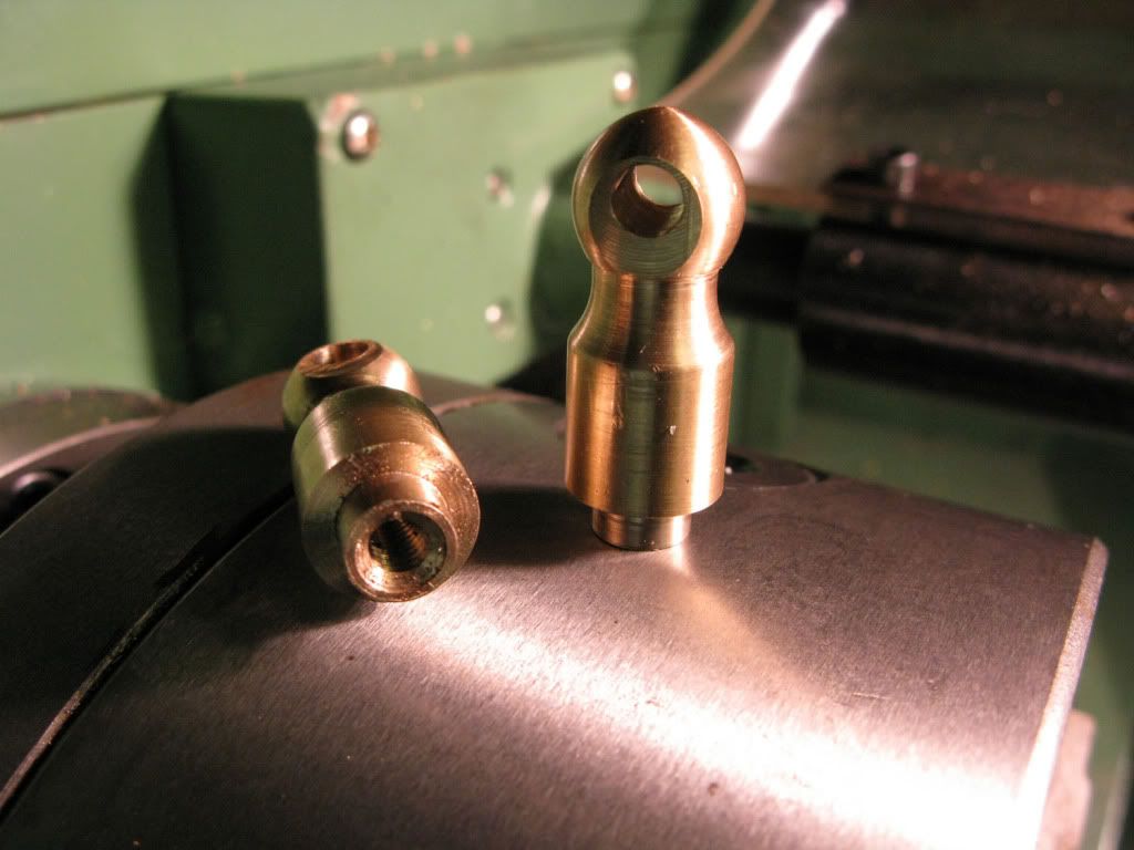
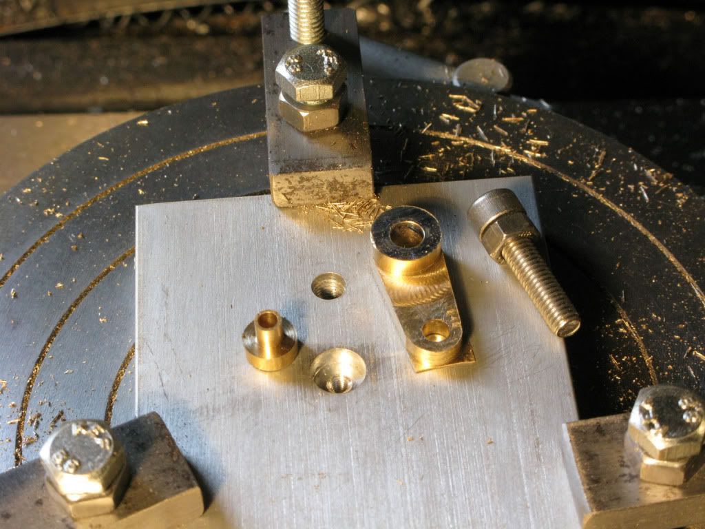
Next I wanted to try Marvs 4jaw setup on round stock so I put in some brass rod to turn the 6mm thick brass sections of the column. As Marve states, with a dedicated DI and two keys, setting up is a breeze, and they were both done and parted off before I even thought of pictures, so I took a mockup of the start chamfer. Both edges have a complete radius, Two chamfers and a lick with a file completes them.
Having still not finalized how I was going to progress the tapered column I swapped back to the three jaw and finished off the col base, giving the end a chamfer and tapping a 6mm hole.
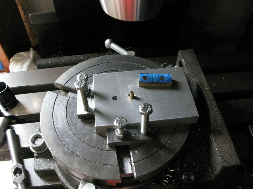
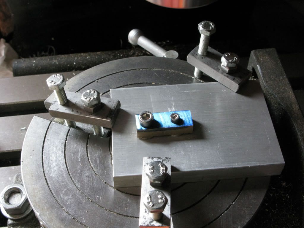
Now for the biggie. Back to the mill. I do have a rotab but no tailstock, Options, set to and make one, wait and buy one or improvise. The last one won.
My problem was that whilst I could hold the taper in the chuck mounted on my rotab, thanks to the 10mm parallels I had left each end. I also needed to firmly hold the other end. The solution I arrived at was to mount the rotab in a position where I could hold the other end of the piece in my vice using a vee block, that would also mean having to sit it on parallels to give it sufficient height.
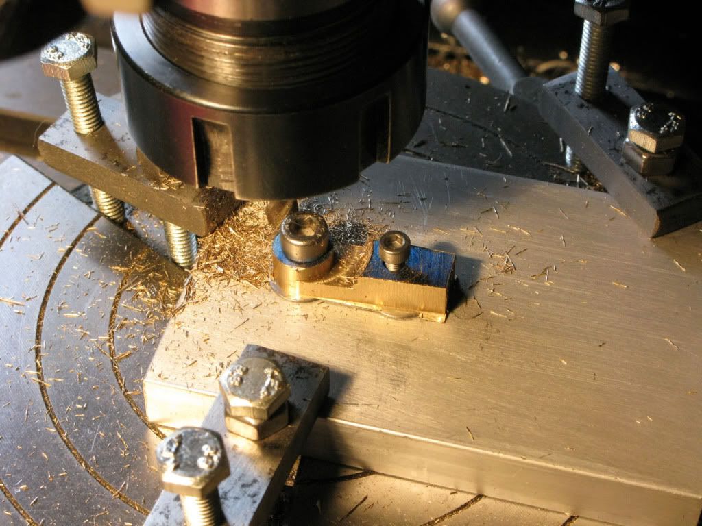
The resultant positioning meant that none of the holding down points coincided with the table slots, so I had to use clamps to secure everything. From then on it went like clockwork. 1 Zero rotab, 2. pinch vice, 3. mill slot with 12mm Bull nose end-mill, 4. loosen vice wind rotab 60 degrees, 5. pinch vice. And so on until rotab was back to zero. Increase the Z depth and start all over again. Keep going until the slots look right. Hang a sign in front of your eyes saying. DONT FORGET TO TIGHTEN/LOOSEN THE VICE
The finishing touch was to put in the lathe and using 400 W&D give it a final polish, then drill and tap the 6mm holes each end, back in the mill, then marry it up with the col base and brass section.
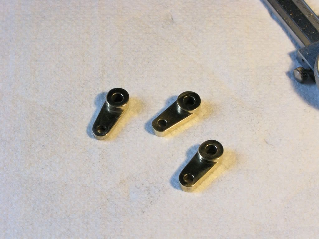
") I especially like the detailing up the column
I especially like the detailing up the column