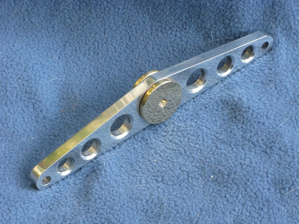
A novice build of Brian's double scale beam engine

Home Model Engine Machinist Forum

Help Support Home Model Engine Machinist Forum:

This site may earn a commission from merchant affiliate links, including eBay, Amazon, and others.

Lesmo

Well-Known Member
Joined
Mar 1, 2011
Messages
142
Reaction score
16

First a thank you to Mike Freeman, Dave Piper (steamer) for sorting the problem I had when joining this great forum, back in March. Since then I have been trawling the site, soaking up info on how to get things done as I guess all novices do.

For my first project I decided, after reading both Brian’s and Kvom’s builds that I would have a crack at this engine myself, even though my skill level is still on the bottom rung of the ladder. I recon if I can make it shiny enough, even if it doesn’t work at least it will make a nice ornament and give me some experience in the process.

For the benefit of other novices I will describe my build (cock up’s and all) in reasonable detail, hopefully, without the sending the reader, to sleep.

I had intended to complete the build before describing the journey but realized part way through, that posting as I went would probably be better as I, and any novice reading this, may get some useful advice and tips on better methods to have used in the production of the various bits.

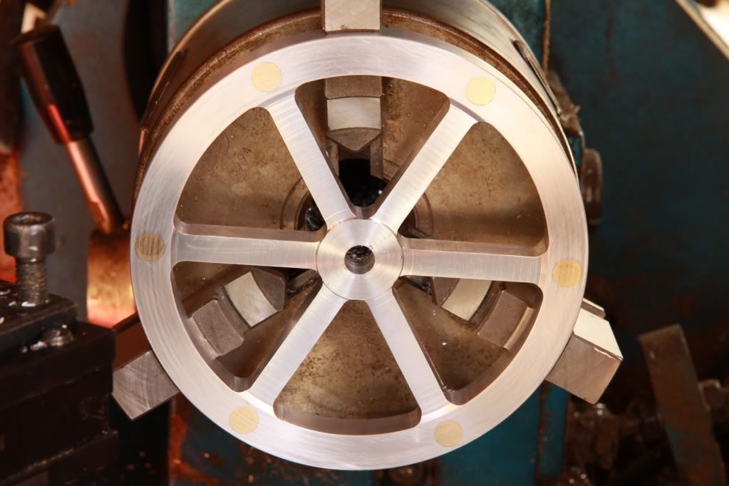
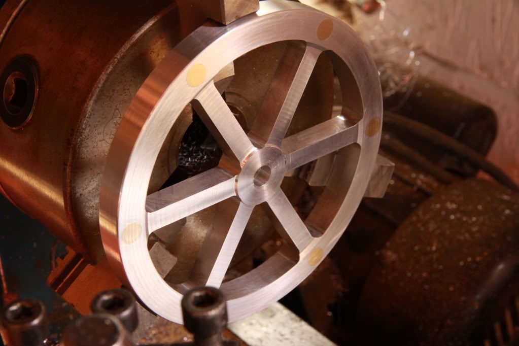
The story of my progress so far. I started with the flywheel and like Kvom I decided on a spoked flywheel, this being more difficult, would be a good test for my first play with a mill, but rather than using steel I would take the easier option of using ally.

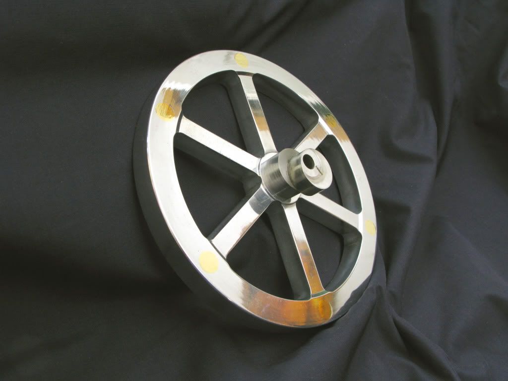
I tried without success to download Marv’s flywheel prog, so I drew it out on my cad package, using node points at the centre of each hole to be drilled. During the process I thought that a little extra weight added around the rim would be a good idea so added a node mark above each spoke, for the 8mm holes, to take the brass weights.

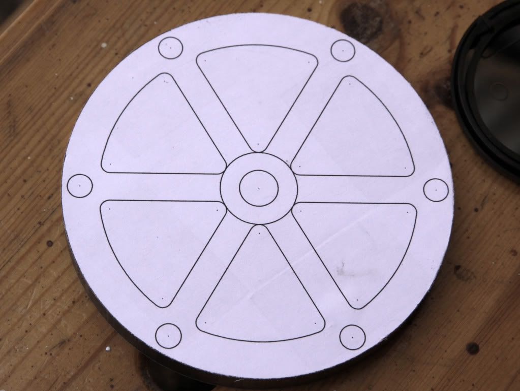
My marking out ability is crap, so I printed the drawing full scale so that I could, using double sided tape attach it to the faced ally blank using the centre drill hole for location, a process I continued for some other parts. I forgot to mention that all my parts have to be redrawn, measurements being converted directly from Imp to Metric except hole sizes which were to the nearest metric size.

Sawn blank
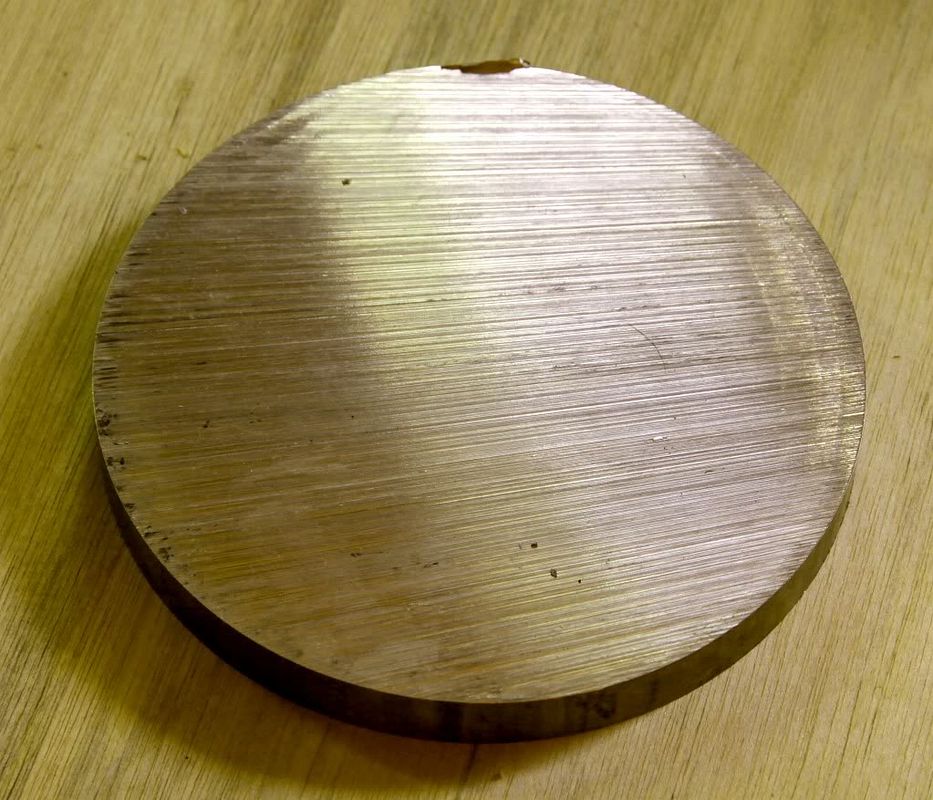
IMG_2070s.jpg

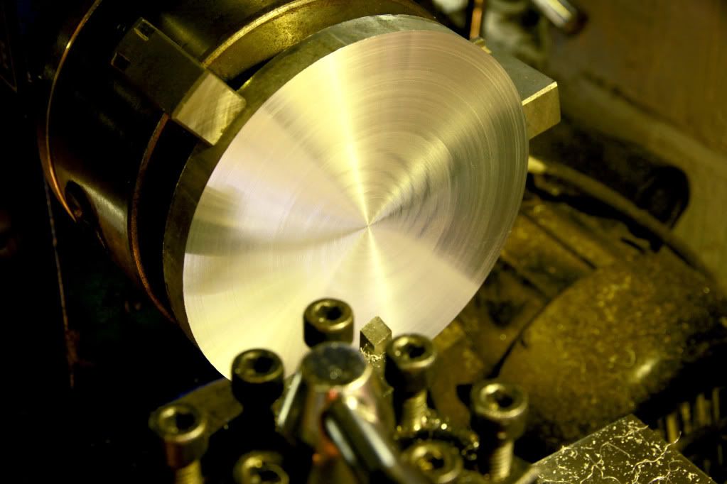
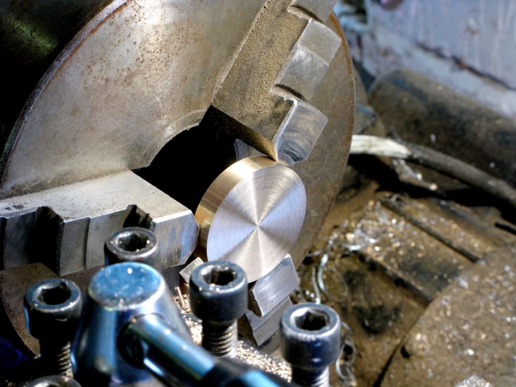
Both sides faced
IMG_2071.jpg

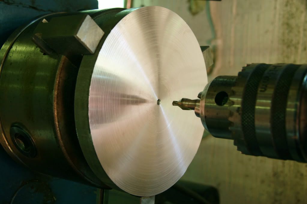
Centre drill blank as my zero point.
IMG_2073.jpg

Blank with drawing attached
IMG_2074.jpg

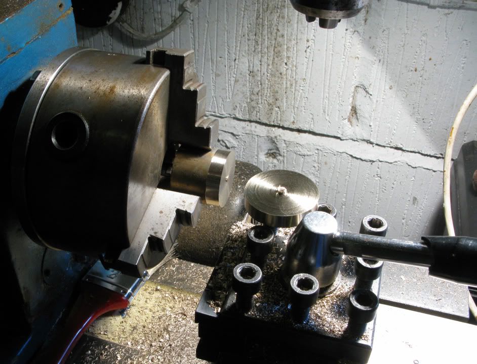
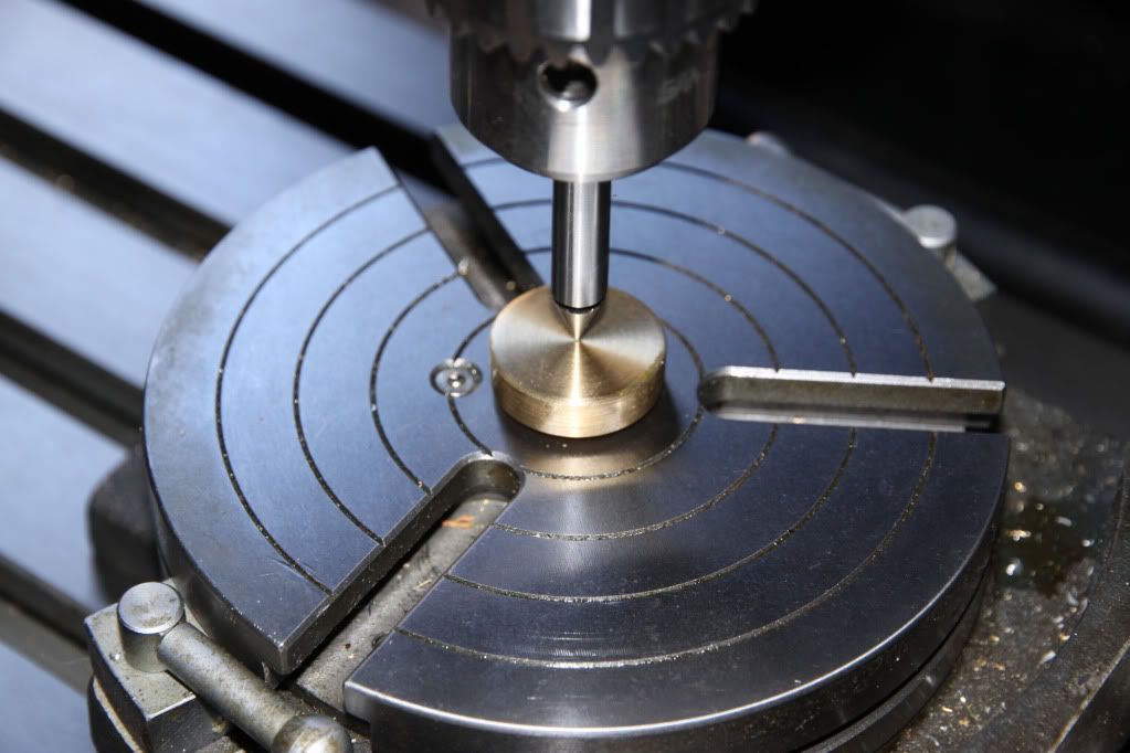
I now had to set up the rotab on the mill, and my 3jaw on the rotab, so to help get things close, I turned a piece of brass with a 2mt stub to fit into the rotab,
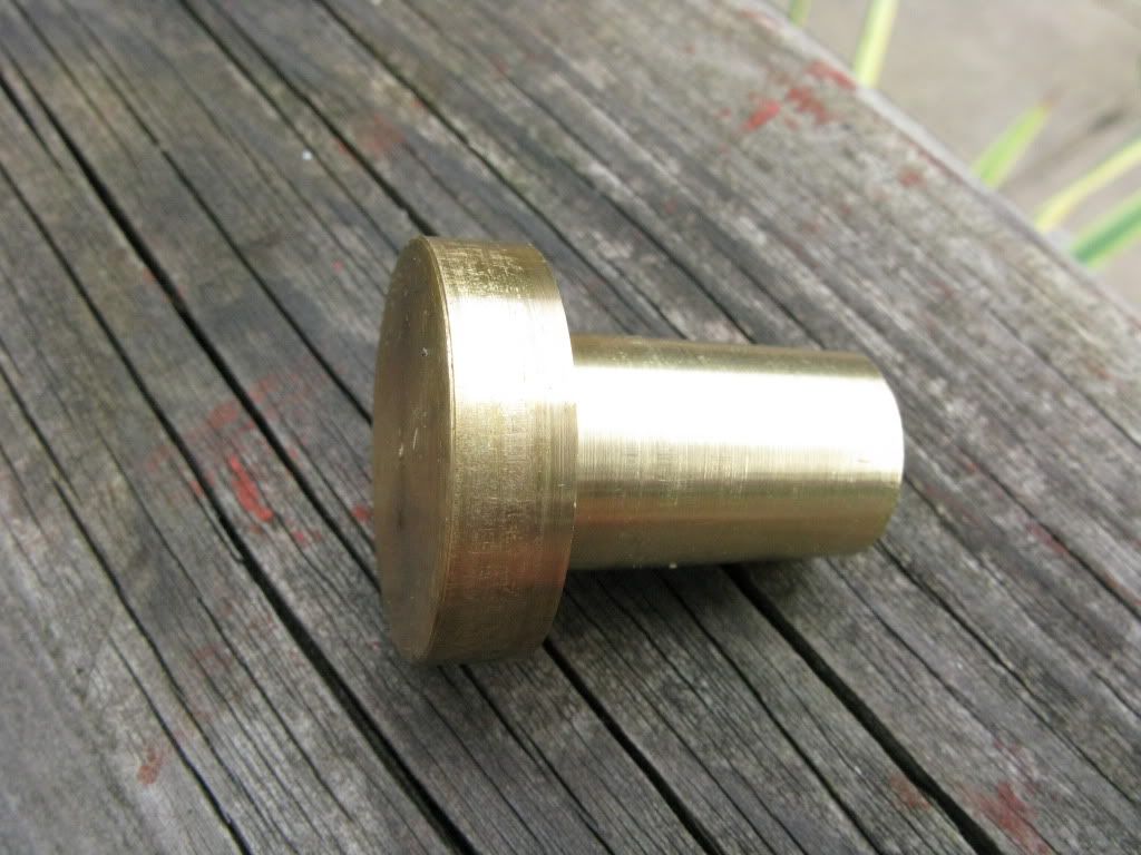
IMG_0865.jpg

and a boss to fit the back of the chuck, plus a centre dimple for location.
[
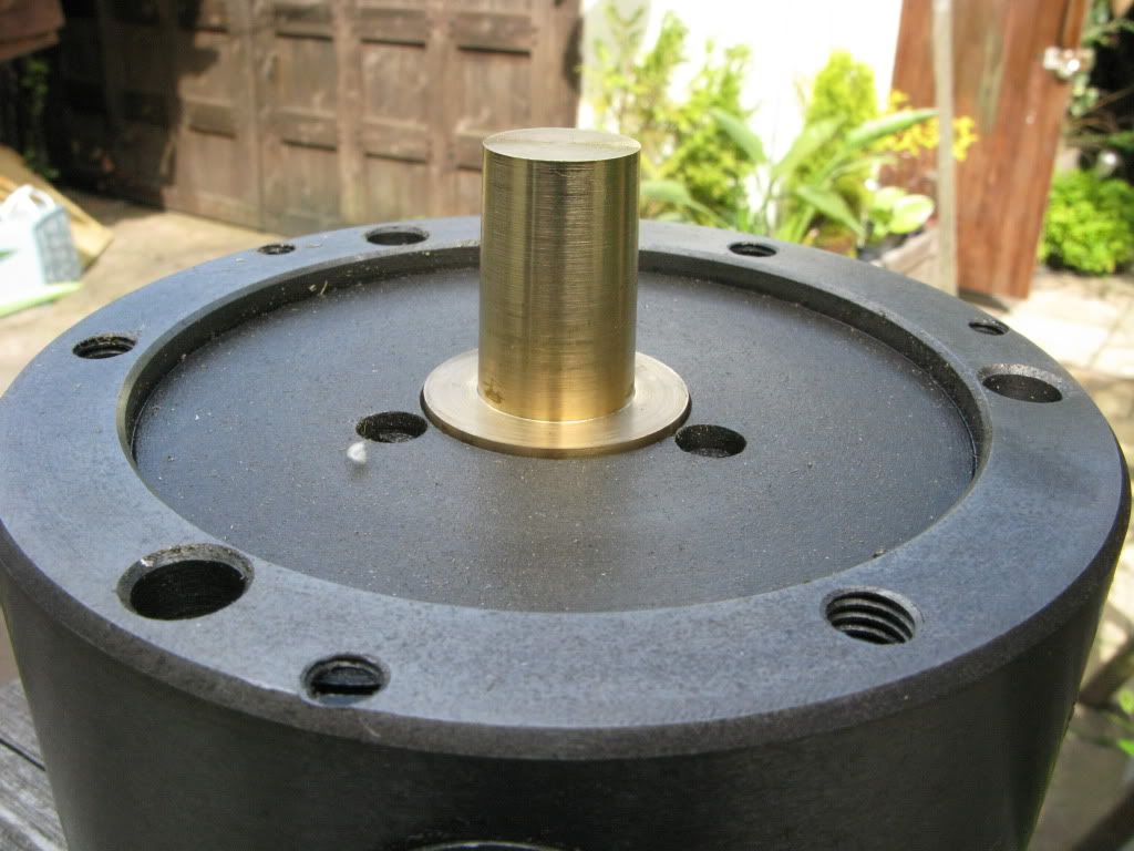
IMG_0863.jpg

Using the brass stub I set the rotab on centre then dialed it in and locked it down,
IMG_2076.jpg

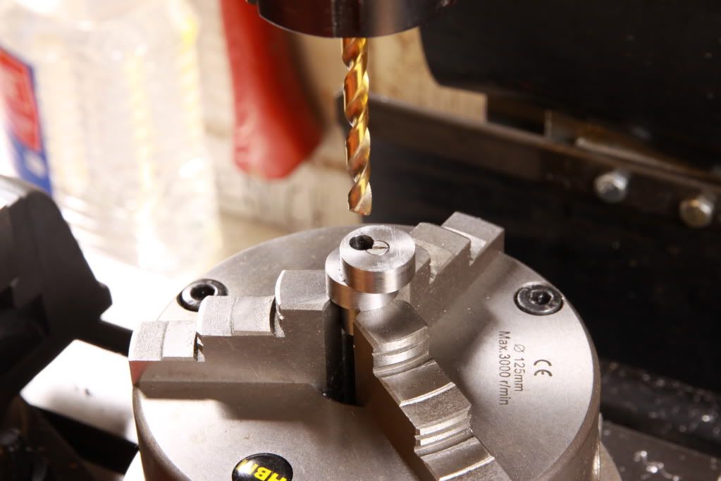
fitted the chuck and dialed that in, finally securing the blank in the chuck jaws, using three 3mm drills as parallels to give clearance from the jaws . Then I checked the centre node using a centre finder. (a better method would have been to locate the drawing last using the centre node) even better would be, improve my marking out ability.

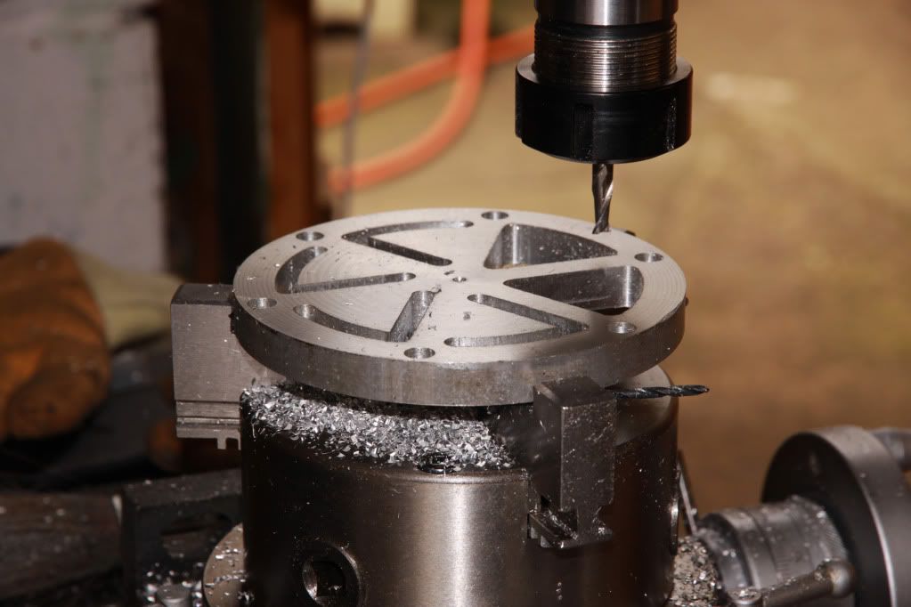
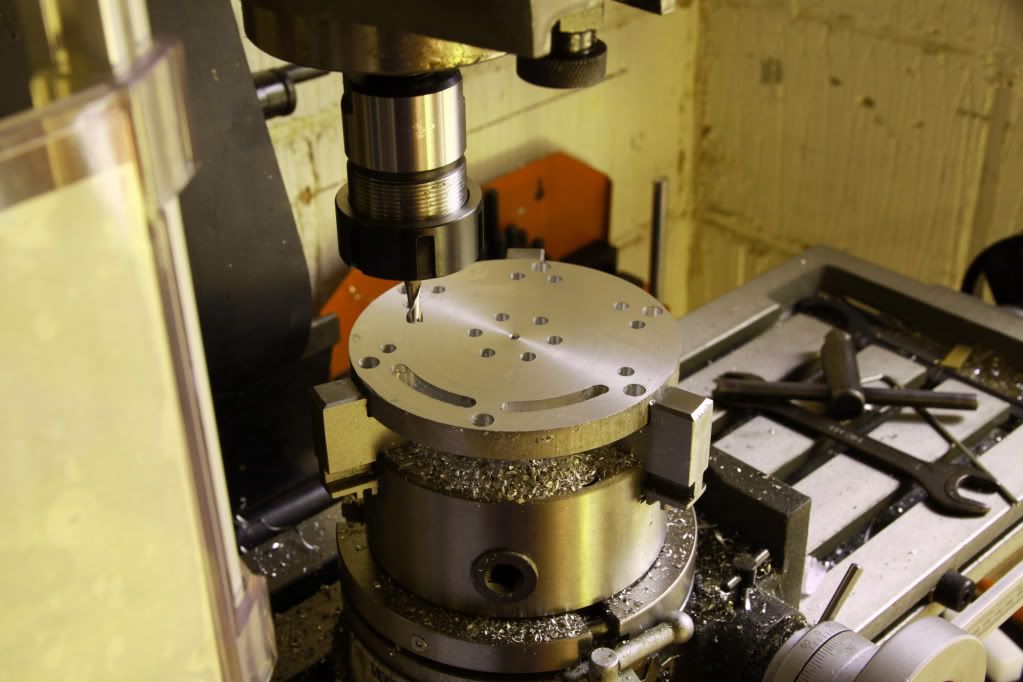
Using a 10x magnifier and centre finder I lined up the first hole of each ring, after getting them aligned across with the X axis then drilled each of the six 6/8mm holes turning the rotab dial the required number of turns between each.
IMG_2080.jpg

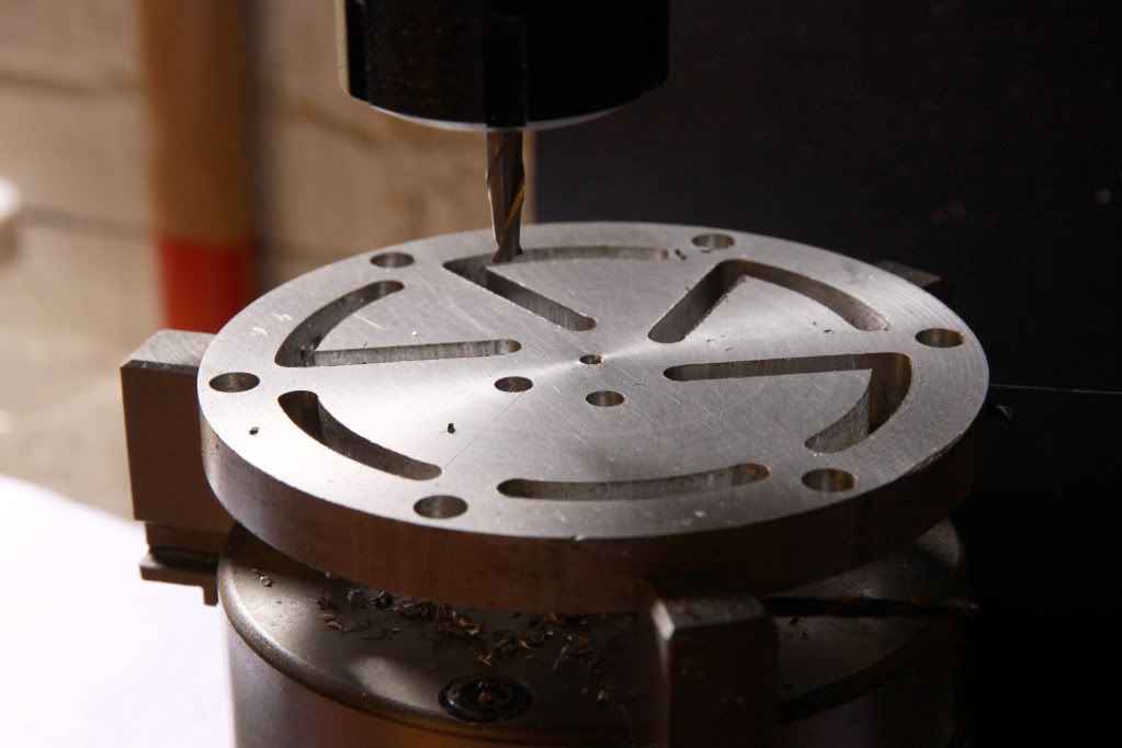
I followed the same procedure to trepan out the triangles, completing one slot of each before continuing to the next.
IMG_2085.jpg

IMG_2089.jpg

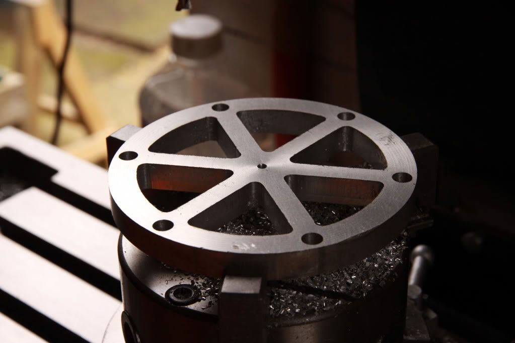
I milled in both directions and all went well until at the start of two outer curves I turned the rotab dial the wrong way and screwed them up. I completed the trepanning ant the cock ups were so visible I gave up for the day.
IMG_2091.jpg

Later that evening I thought of a way to rescue the piece from the scrap bin. Someone with experience would have recognized this immediately, I simply had
to re-drill all the holes from 6mm to 8mm. I drew it out first, to see what effect it would have and it looked just fine, so the following day I using an 8mm end-mill I re-drilled the two screw up’s first, to see if 8mm was enough to correct the faults and it was, so I drilled the rest and joined up the dots.

The next step was to make and fit the brass dowels
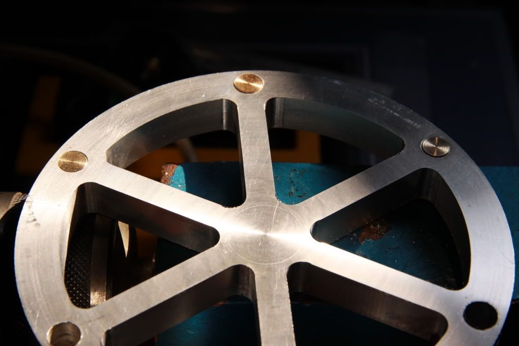
IMG_2101.jpg


This looks like it will be a fun post to watch!!!
I am also a total NOOB to this field!
Hopefully i will learn something and will help me on my way!

Unfortunately summer is not the best time to start a build...
Too much outside work to catch up on!

But i will be following you on your journey!
Best of luck!!

Andrew

ps- your last pic did not post...
 
Thanks Andrew, I posted only the first part, to check if it looked ok but during the process I had finger/keyboard trouble and the site zoomed out to the point where I could no longer read any of the text.
It took a while, and was after much head scratching and hitting various combinations of keys to try to reverse it to full size that I examined the Google home page and found it had a zoom function that I had somehow activated, so I probably added the rest, after you looked.
 
Each hole was reamed with an adjustable reamer to get a nice tight fit, and a dab of locktite for good measure.

The flywheel was faced both sides, then repositioned so that the chuck jaws held it internally in order to face the outer rim and drill the centre hole.
It was then I realized that I had forgotten to recess both faces so I reset it in the jaws and took out 2mm each side.

IMG_2106.jpg


IMG_2105.jpg
 
Wow what a great looking flywheel you got there. Keep it in no time you will have a running engine :bow:

Dave
 
Thanks for the encouragement Dave. A runner, now that would be something else ;D
 
That's looking great Lesmo...and of course it will run... and look good doing so :) I like the contrast of the brass dots on the flywheel too!!

Bill
 
It is looking good - a credit to you!
 
Lesmo, that is one fine looking flywheel. Great job !!! I will pass on a trick that an old toolmaker taught me. When chucking or clamping on a finished surface, put a piece of thin card stock or heavy paper between the work surface and what you are clamping with. This will help to keep unwanted makes on your finished surfaces. I have a stack of old IBM cards from the 70's that I have been pulling from for the last 40 years.

Keep up the great work and I am looking forward to seeing it run.
 
Thanks for looking, Bill, Tel, and Steamin, and thanks for the card tip, it would be a shame to put marks on a nice shiny bit, and although I know the shine is best left till last, I just cant resist a bit of spit & polish as I go, so for me that advice is particularly relevant.
 
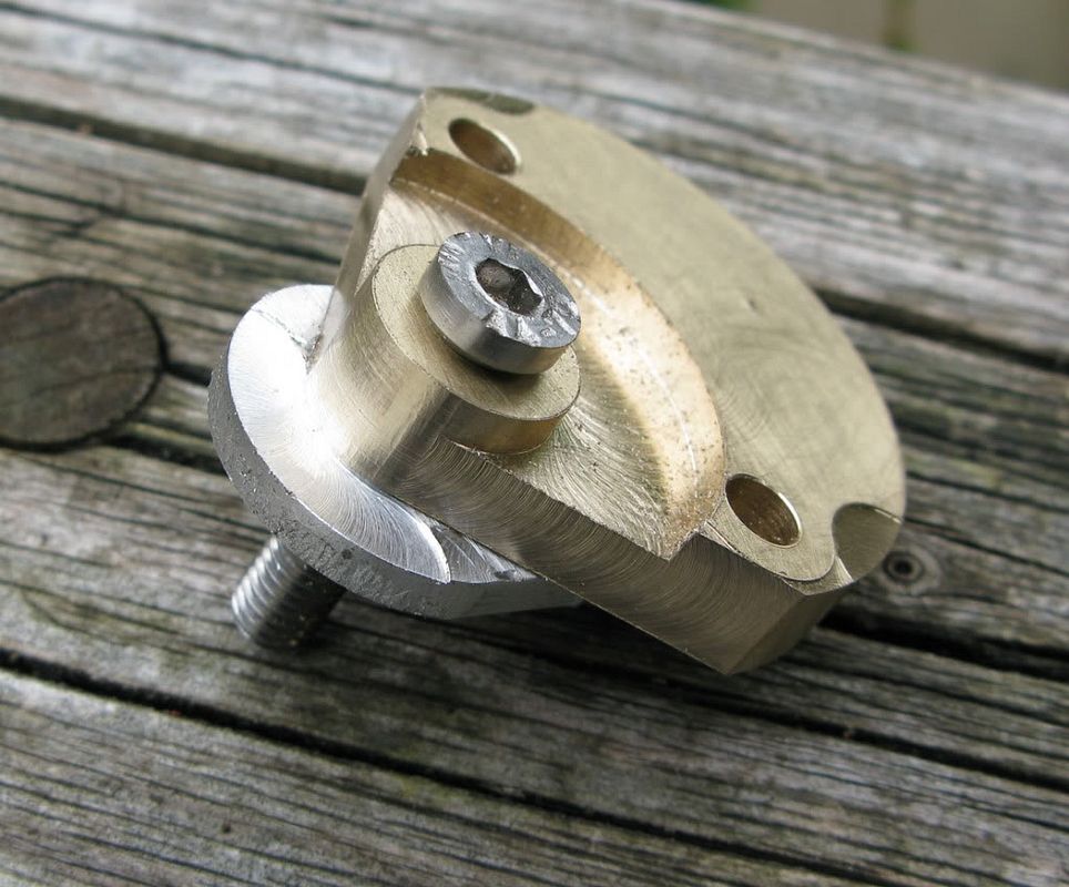
Having completed the flywheel, apart from the final bling that is, I thought it would be a good idea to make the bit that fits into it with the offset that drives the valve mechanism, as I thought that this part was going to be a stumbling block for me, as I don’t have a 4 jaw chuck and it would probably take me a fortnight to set it up if I had one.

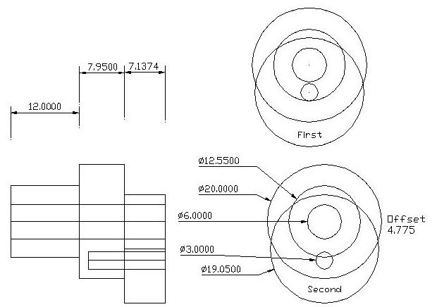
I decided to make it in two parts as KVOM had done, but had not detailed. So I drew it out and decided there was room for a 3mm csk through the centre of the offset portion which I could now drill whilst it was still in the lathe chuck. Drill & tap a corresponding hole in the other part, screw them together then put a 6mm hole through both, to ensure alignment.
The drawing shows the first and second attempts

A_FWeccentric.jpg


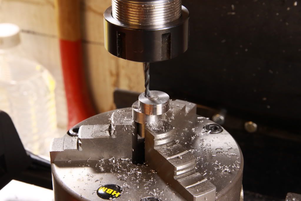
First I spot drilled, then using a 4mm drill put a pilot hole through both,

IMG_2108-1.jpg


Following up with a 6mm drill which just took out a small portion of the screw head

IMG_2109-1.jpg


Quite satisfied with the result of what had taken a day to complete, I removed it from the chuck, only to discover that the $$£%%32 drill had wandered off centre, screwing the thing completely. At this point I vacated the shop before I could reach for a hammer.
After looking at the scrap eccentric I came to the conclusion that the reason the drill had wandered was because the 3mm screw was too close to 6mm hole and it had just broken through to the screw threads. Modifying the drawing that evening, I started the whole thing again the following day.

Fortunately I just had enough material for one more try and this time it worked, but, belt & braces I ordered a 6mm HSS boring tool, put the Ecc back in the lathe and patiently bored it to ensure concentricity. After all there is nothing worse than a wobbly flywheel. Well not much.

Pic of new one fitted to partly polished flywheel (could not resist the polishing bit)

IMG_0878.jpg

 
I'm following along. Looks good!

My eccentric has a small outer flange to retain the eccentric strap. This may not be necessary, but when you get it finished and find you need it, then it's an easy part to remake.
 
Thanks Kvom,
that flange sounds like a good idea, maybe I will attempt it before completion, as I have just taken delivery of a 4 jaw and plain adaptor-plate that I have yet to machine and hopefully not ruin in the process. If all goes well, I may attempt to remake the eccentric as a single part using the 4jaw, just to get some experience, I don’t know though, it may take me until Christmas and completely fill the scrap bin.

I am following your Kozo A3 with much interest and have so far read to the end of page 5. What a huge project to undertake. I wish you well, and not too many, Aw $hits

Les
 
Having done the eccentric I decided to stay with the flywheel parts and make the large end of the eccentric rod. I started by facing a chunk of brass rod, parting a slice off

IMG_0781.jpg


Then facing the other side.

IMG_0783.jpg


I then drilled the centre whilst I still had it in the chuck, I would later bore it to fit the eccentric using the mill, when I received the boring head I had on order.
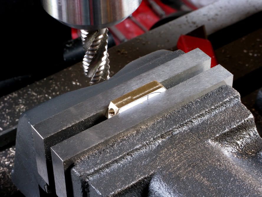
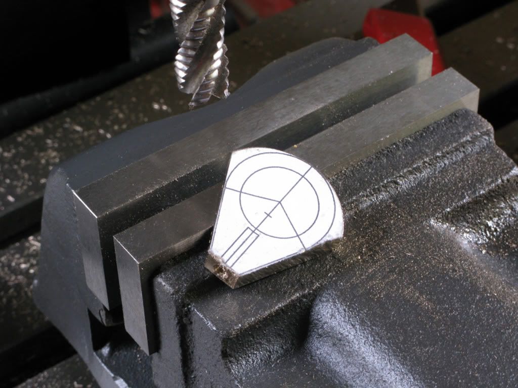
I had already drawn the part and printed a full scale copy which I cut out and carefully attached to the blank. (no pic) then I set it up in the mill vice, using a piece of square of tool steel to get it square, milled a flat, then drilled and tapped it to accept a 4mm rod. I used the same method to mill both angles.

IMG_0749.jpg


IMG_0750.jpg


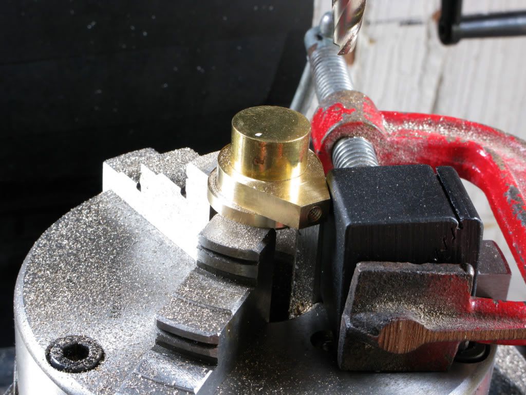
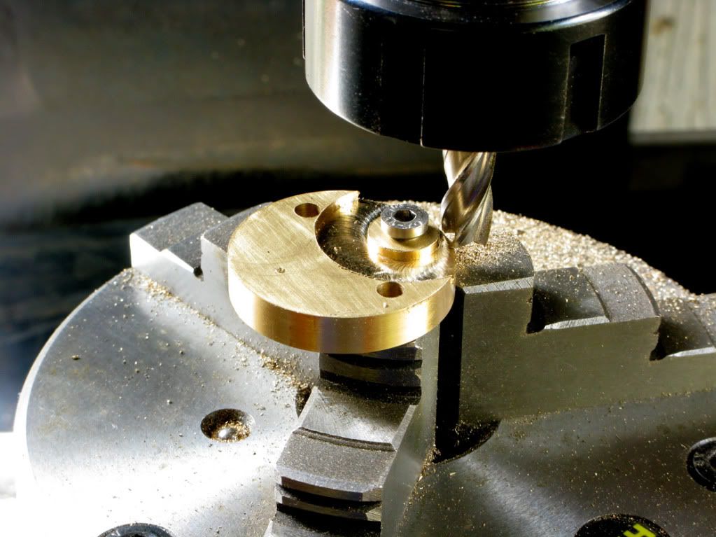
Next I turned a brass plug to fit the centre and found a thick piece of brass scrap to use as a sacrificial packer, then set it up in the rotab chuck to mill the outside curve.

IMG_0772.jpg


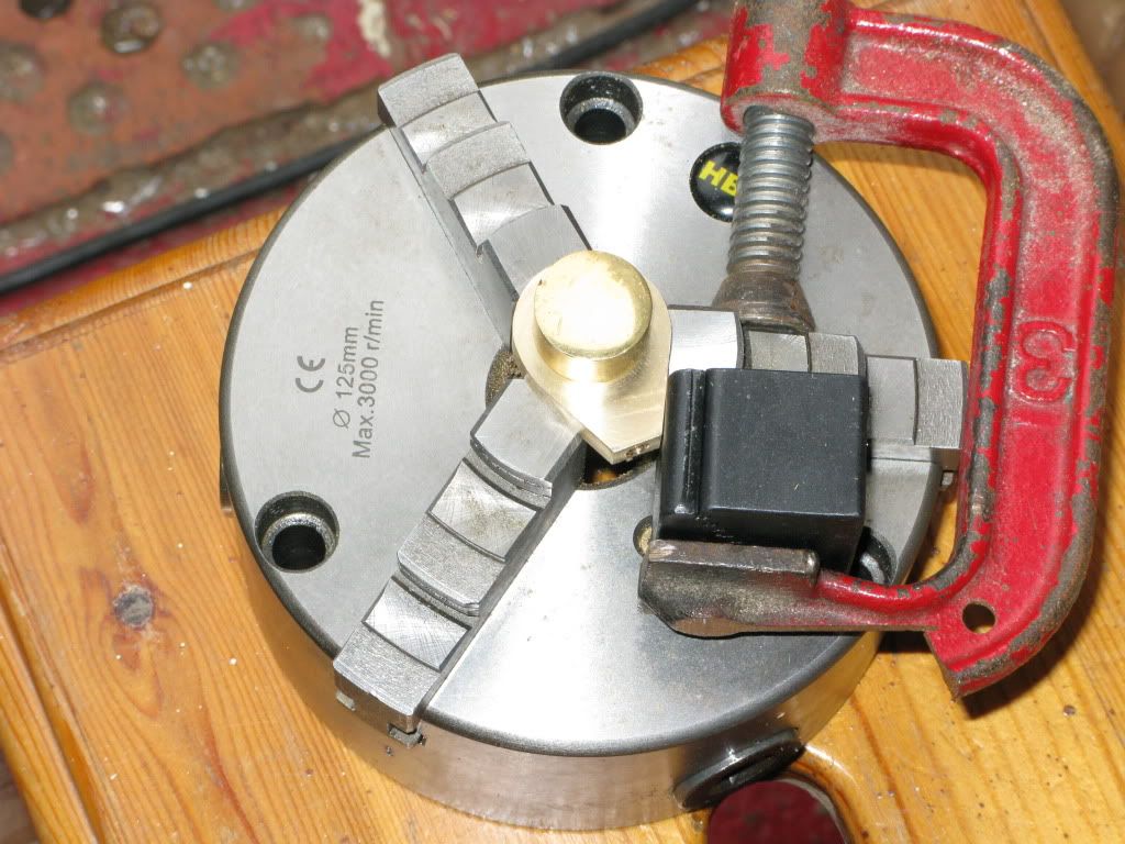
I later mocked up the same setup with the chuck removed just to give a clearer picture.

IMG_0758.jpg


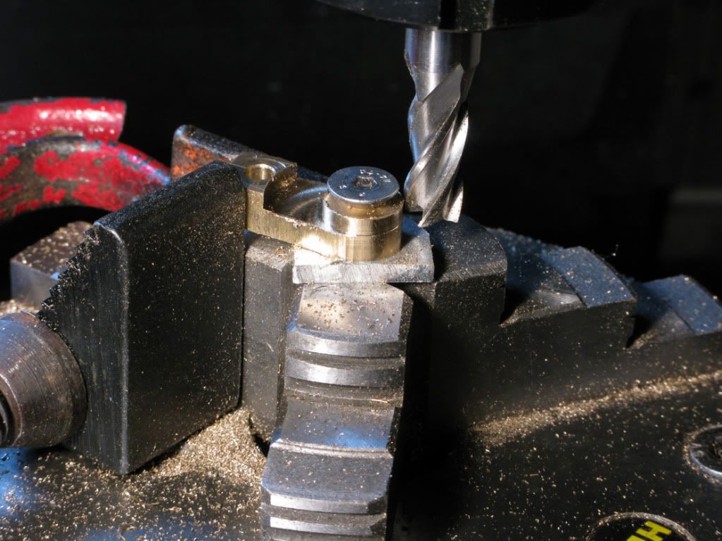
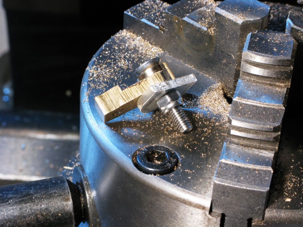
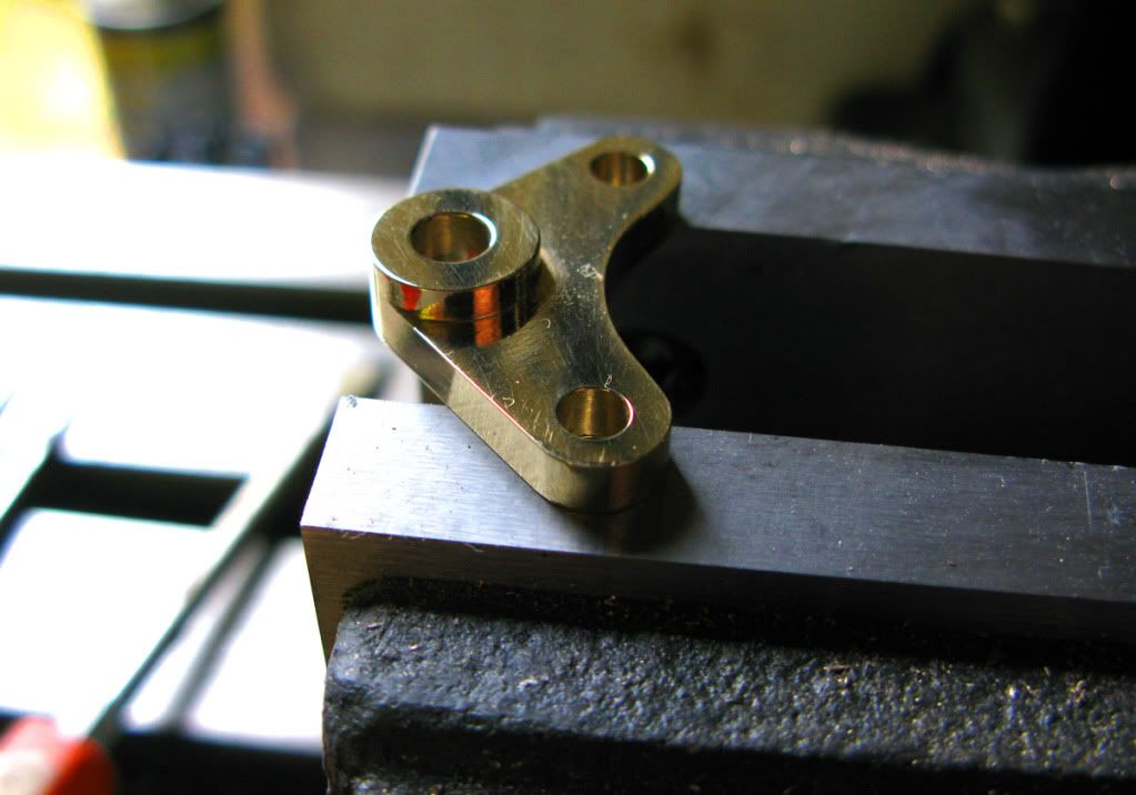
The lower valve lever was next on the list, so another slice of round brass rod was machined, faced both sides, drawing attached to disc, holes drilled and then hack sawed to the approx width. It was then attached to an ally off-cut using a 4mm csk screw & nut, which held it in the rotab vice whilst I milled the boss

IMG_0774.jpg


IMG_0775.jpg


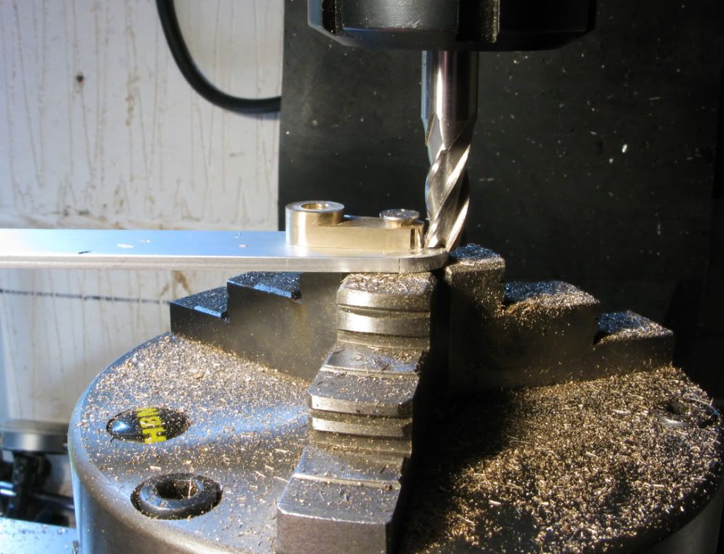
The remaining surplus lump was then machined off and the sides milled using the same setup. Finally switching the fixing to the other hole to radius the small end

IMG_0778.jpg


I did the small end of the eccentric lever using the above method (no pic) and then started on the lower valve lever 2 which looked to be the most brass difficult of the brass part to make.

Following the same sequence I had used for the other parts, faced disc with drawing attached, holes drilled, boss machined.

IMG_0784.jpg


Sides milled,

IMG_0791.jpg


Surplus metal removed to correct thickness, both ends radiused and finally the large radius machined (no pic) This being my first build, and with no background experience to fall back on, I become so engrossed in solving the current problem that I forget to take the pictures. However I did remember to get a pic of the finished item.


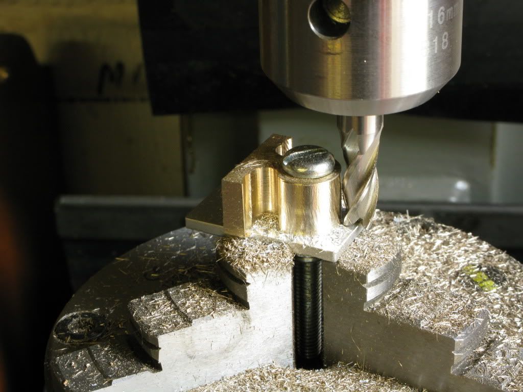
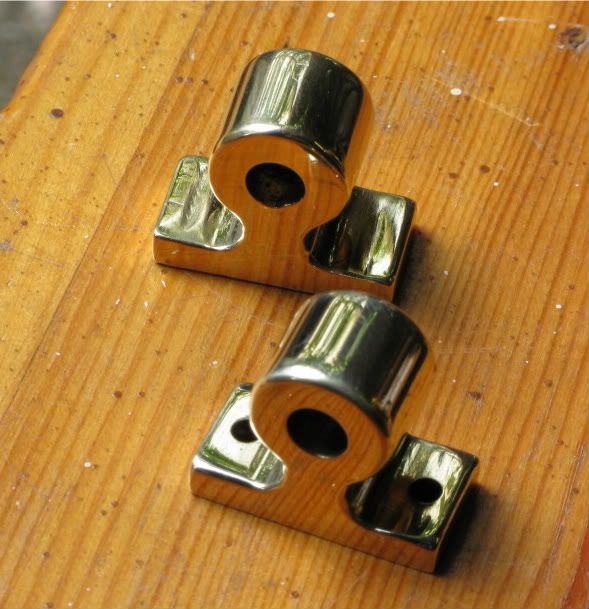
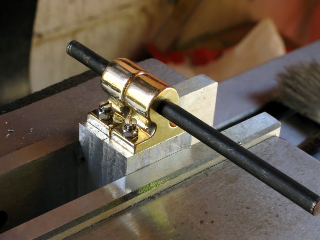
Next thing was to get the base done and make the flywheel bearings. I decided to depart from the drawing like Kvom, and make them seperate from the base. I had also drawn them as 4 parts. The two pillars would be made from aluminium, albeit shorter than usual, to allow room for the separate bearings to sit on top. Then the bearings would be made from brass and fixed to the pillars using 3mm screws.

I decided to make the brass bearings first which would be made using the same method that I had used for the other brass parts, which seemed to work well with no particular problems.

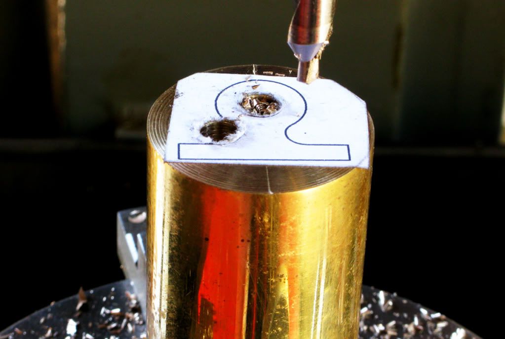
First I faced a length of brass rod sufficient to make them both plus an allowance for cutting and facing. Then I glued on the drawing template and centre drilled the three holes, before drilling them out to size

IMG_0805.jpg


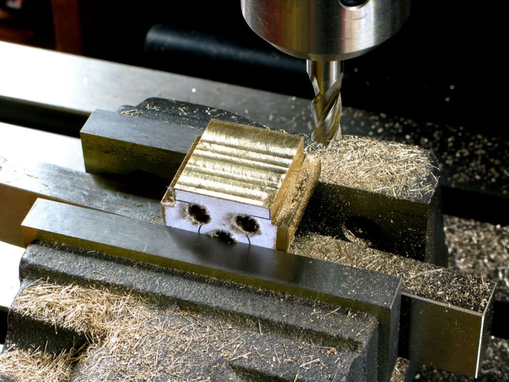
The next step was to profile the base.

IMG_0809.jpg


part the two bearings using the band saw, as I thought it would be easier to mill the radius on the individual pieces using the same method I had previously used, I also doubted the holding ability of single nut with double the depth being milled.

Finally I milled the radius on each one.

IMG_0811.jpg


A bit of fettling came next followed by a quick buffing on the polisher, then the holding down holes were drilled in the bearings using the x axis dro and the home brewed Y axis dro to get them properly spaced and centered.

IMG_0812-1.jpg


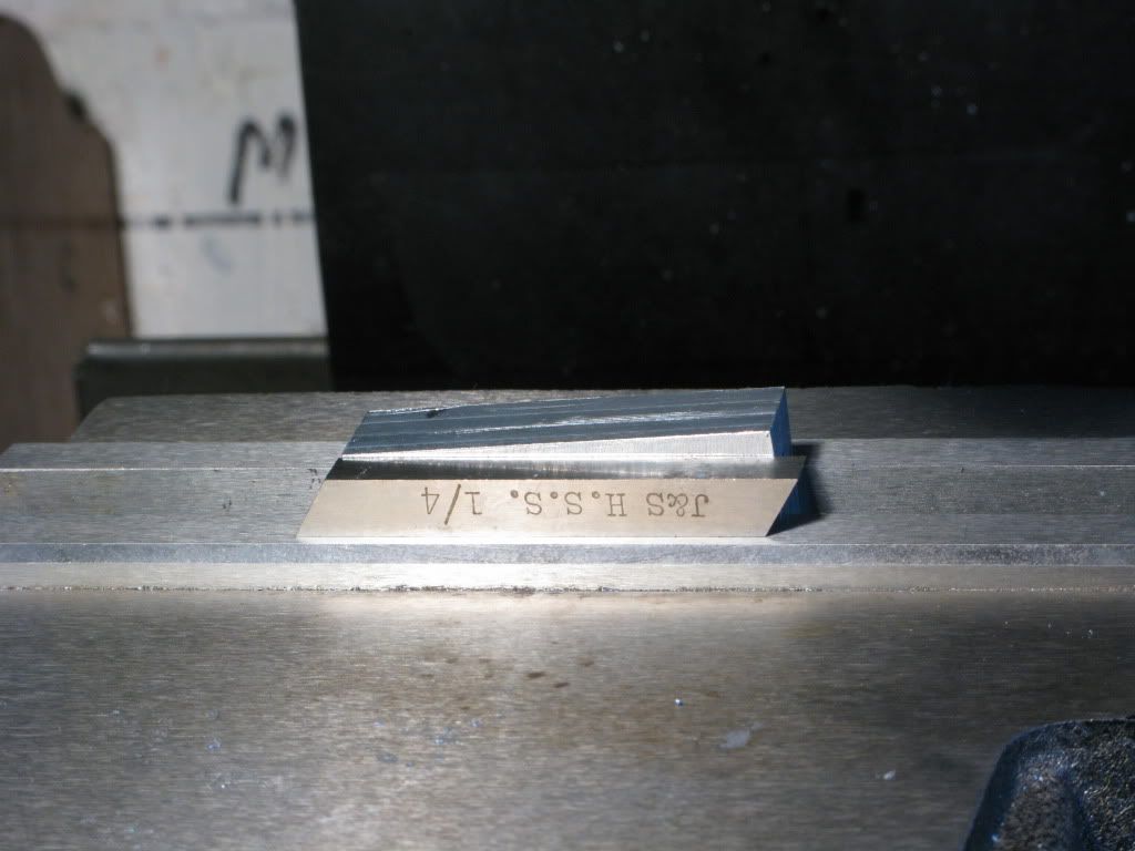
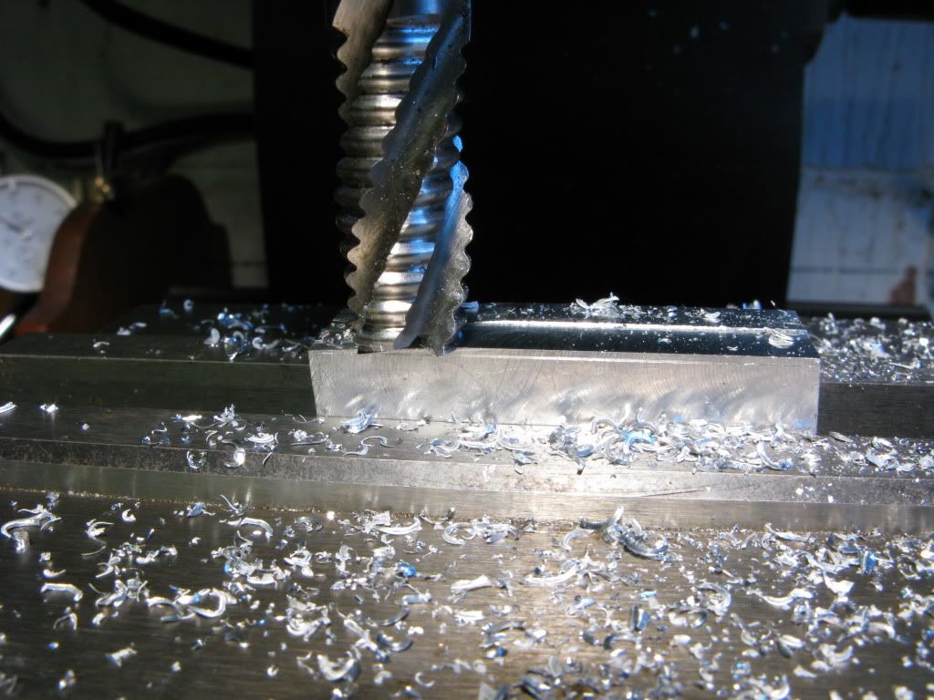
Now for the pillars. First I cut a length from a 32mm square bar, milled it on 6 sides then using a band saw slit it down the middle, followed by milling each part to the required thickness. Each piece was scribed with a 3 deg angle each side, placed in the vice, using tool steel again for alignment

IMG_0844.jpg


I then milled to the scribe lines

IMG_0846.jpg


Both were placed in the mill vice, and the bearing holes drilled in the left side of each. Next they were tapped 3mm the bearings temporarily fixed and using a couple of screws plus nuts. For good measure a through punch was inserted through the bearing in order to ensure perfect alignment, before marking the second holes with a 3mm through punch.

IMG_0815.jpg


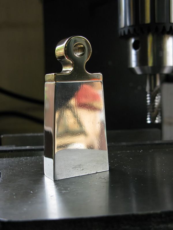
At this point, as I had the polisher set up, I polished one of the pillars, in order to decide whether it would look ok or would need more decorative work, but settled for a plain polished finish, as I thought the contrasting brass bearings would sufficient decoration.

IMG_0849.jpg

 
Your valve lever looks so much better than mine.

I did the separate columns too and have some issues with getting them secure and rigid on the base when attached just with screws from underneath.
 
Thanks Kvom, sorry for the delayed reaction but have been busy upgrading the lathe. Did you overcome the problem of keeping the columns secure, because it look like I will have to overcome that problem too.
 
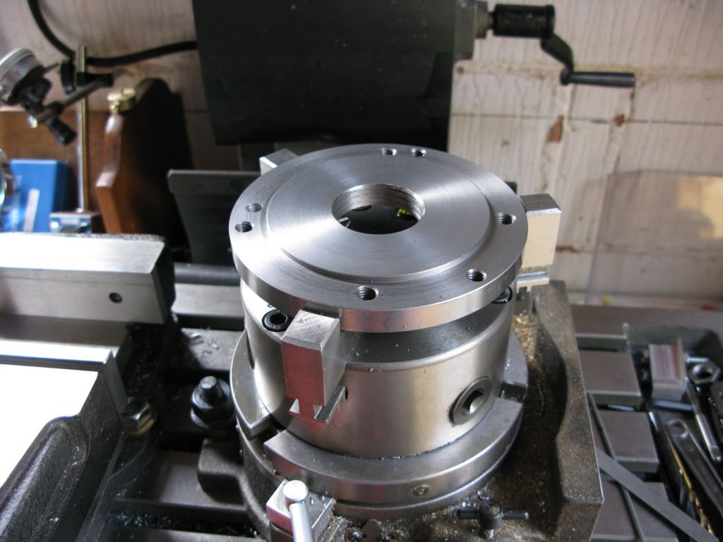
Have not posted for a while as during the build I realized that I needed to improve my lathe capability. First and foremost would be a four jaw chuck, which in turn meant that I would have to make/modify an adaptor plate to fit the 4 jaw to the lathe/mill-rotab.

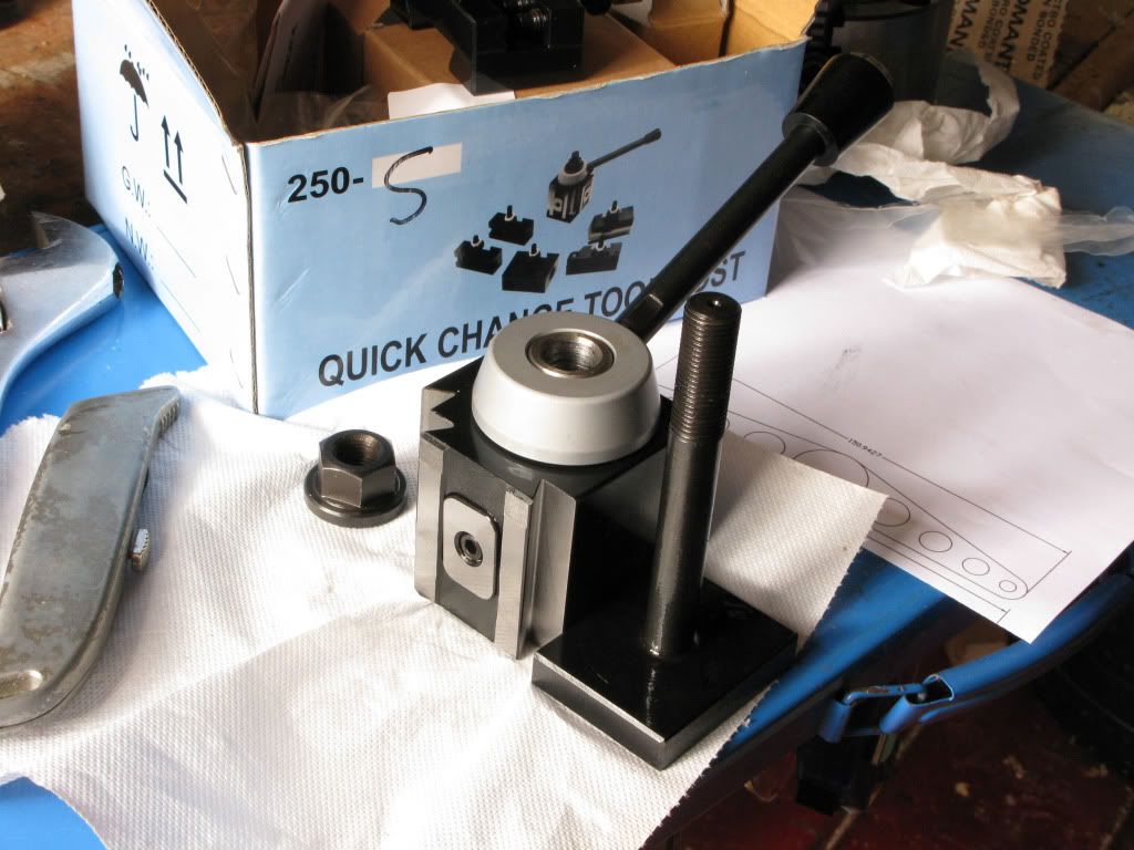
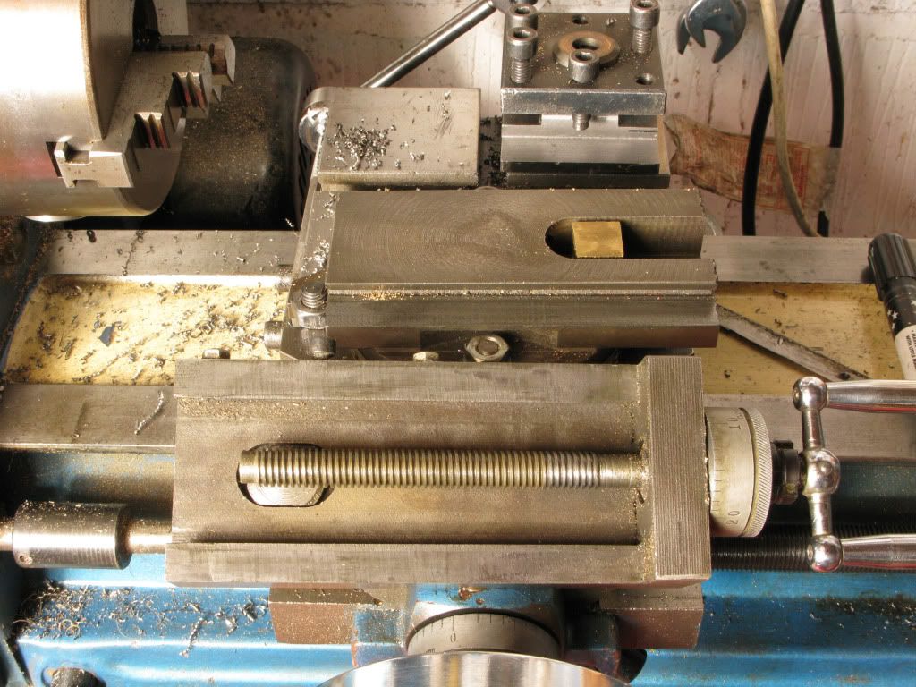
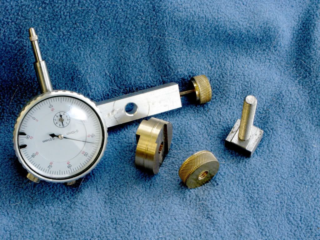
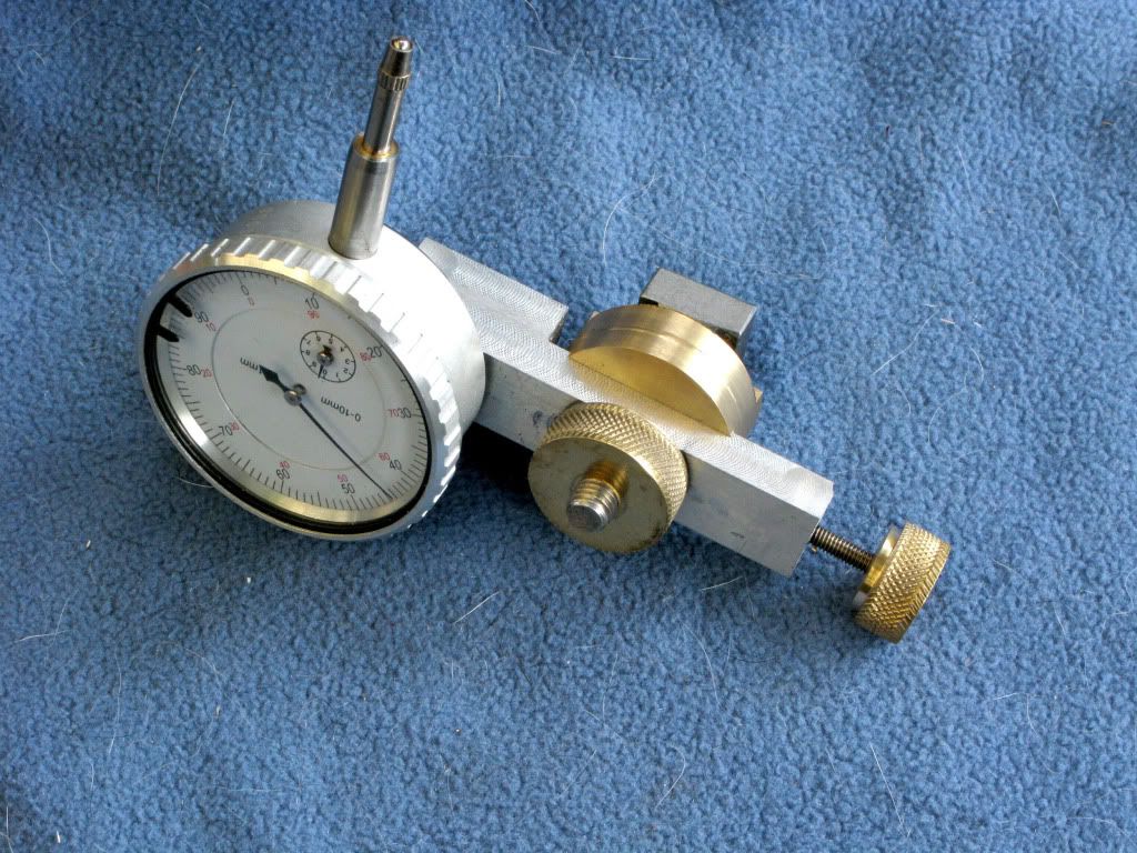
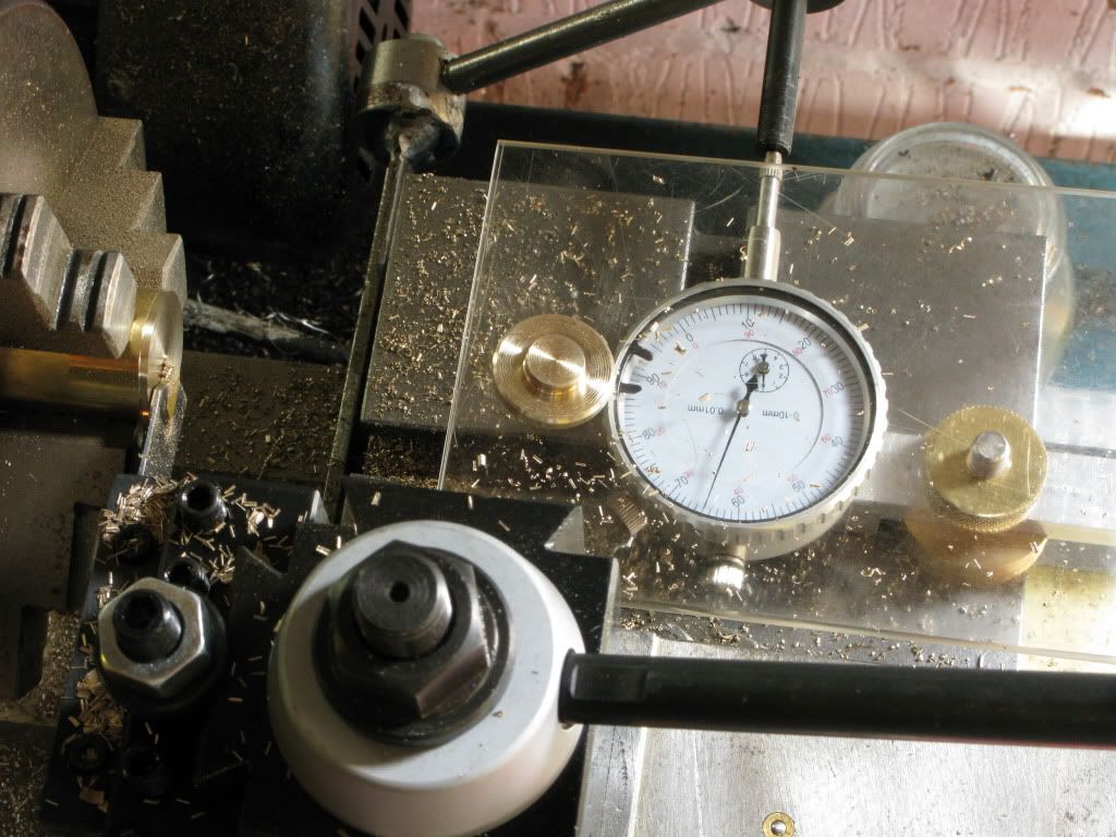
Having read Marv’s 4 jaw setup procedure, I would also need to make a fitting to hold a dedicated dial gauge in the tool-post, and if possible make it double as a Y axis dro, as there is a lot of backlash on the feed screw making it very difficult to creep up on an accurate diameter. The icing on the cake would be a quick change tool-post, as the present method of setting tool heights using shims, is a pain in the a$$.

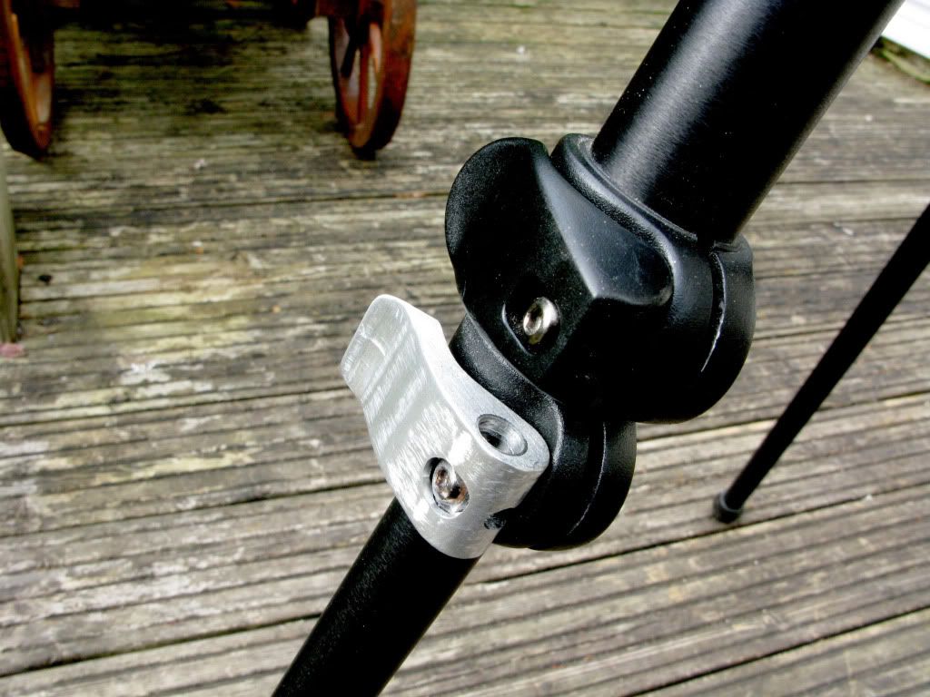
Whilst searching for one of those “It’s here somewhere, tools” tool, I clumsily managed to shear off one of the plastic eccentric leg locking clamps on my camera tripod, with my foot, so a replacement needed to made in aluminium, and being eccentric, I immediately thought, four jaw, so I put the project on hold until I had everything sorted.

I ordered all the parts, including the only back plate I could find that looked as if it could be machined to do the job. It was a 5” dia, one designed for a boxford lathe with a great big threaded boss which would need removing before going any further.

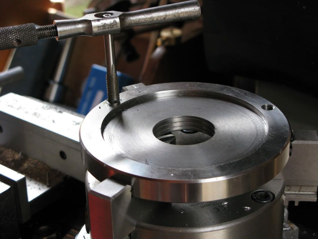
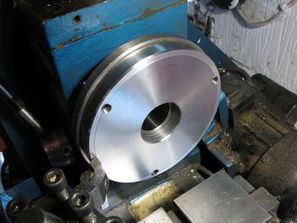
I will not detail the modifications as I am sure most of you have already trodden the same path, but I will include the pictures for the record.


After having machined off the boss and made the recess to fit the existing fixed back plate, the holes were drilled & tapped.
IMG_0889.jpg


Machining to fit four jaw chuck.
IMG_0891.jpg


Completed item ready to go
IMG_0915.jpg


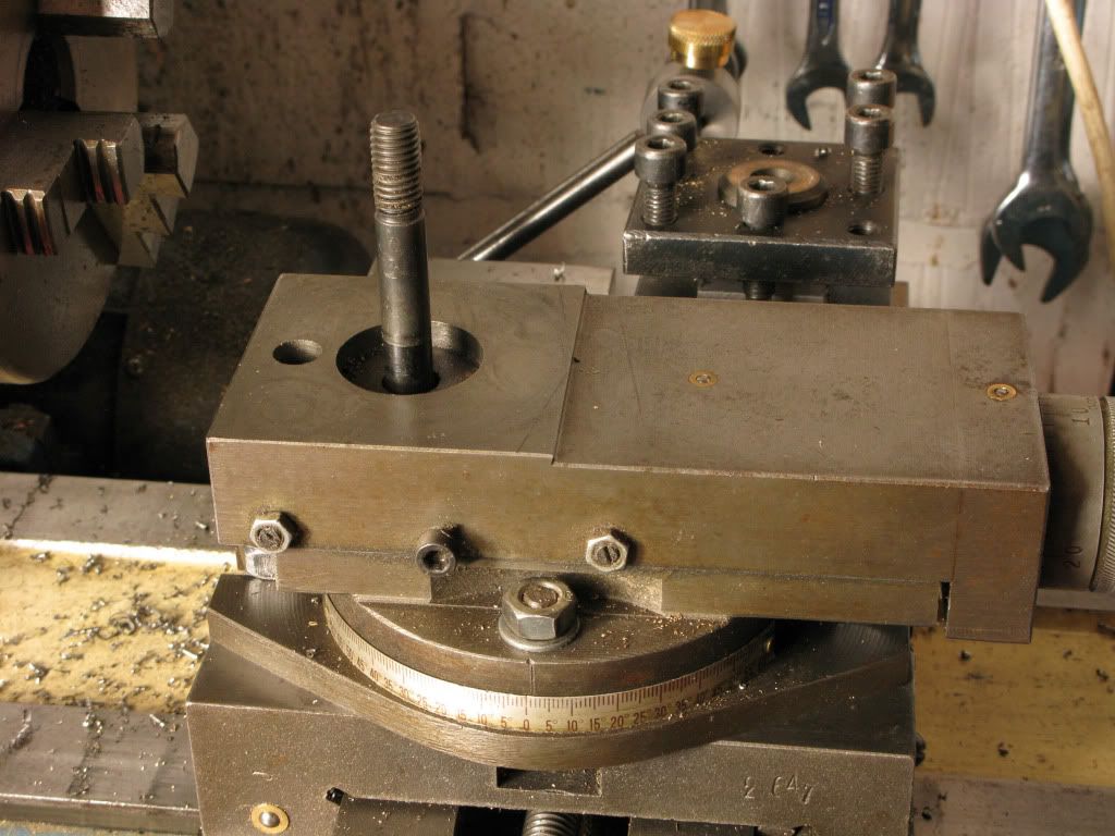
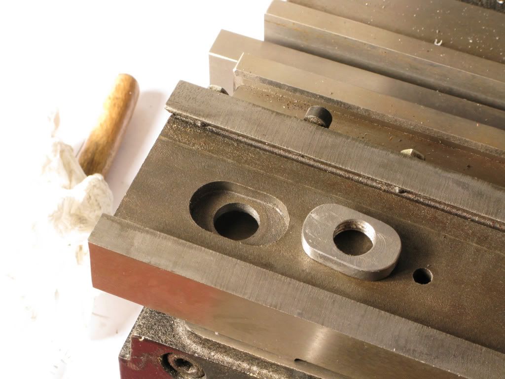
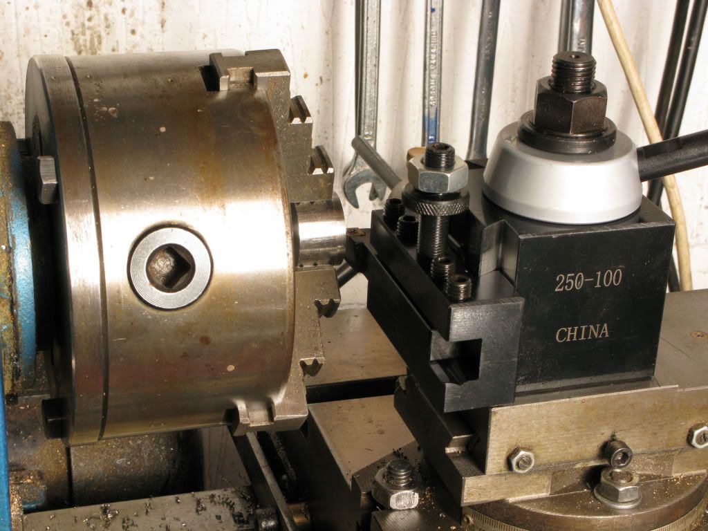
Old tool post in background, 10mm retaining stud.
IMG_0954.jpg


New post has 14mm retaining stud.
IMG_0952.jpg


Top-slide removed
IMG_0958.jpg


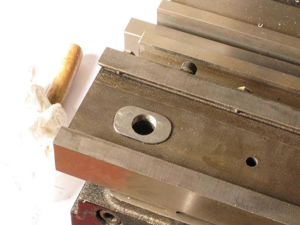
Hole bored to 14mm
IMG_0959.jpg


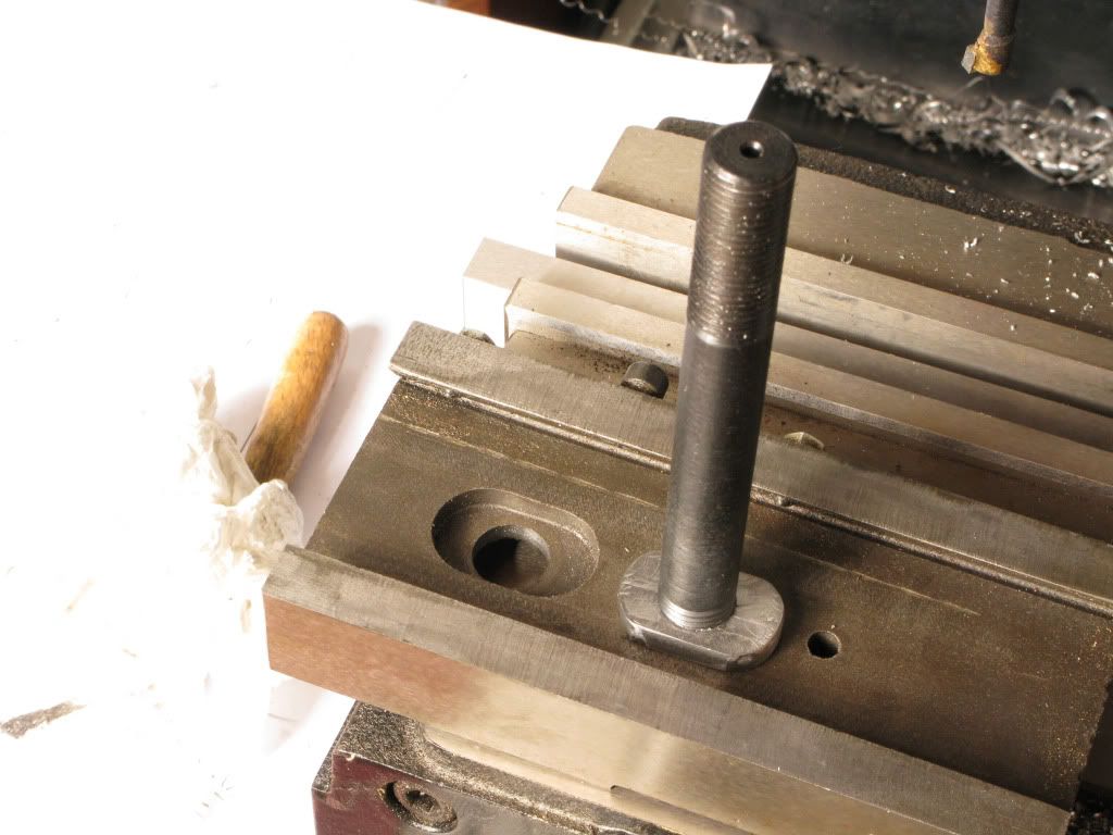
New retaining nut made
IMG_0962.jpg


IMG_0963.jpg


Locktited to 14mm stud
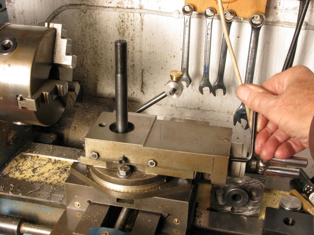
IMG_0966.jpg


Reassembled
IMG_0974.jpg


New post fitted
IMG_0979.jpg


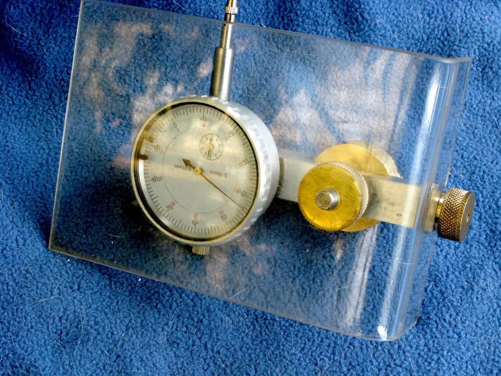
Dedicated dial indicator can be held in tool-post, or fitted to cross-slide to act as dro
IMG_0997.jpg

IMG_0998.jpg

IMG_1000.jpg


In use as dro
IMG_0987.jpg


Tripod now fixed
IMG_0995.jpg


And now on with the Elmer.
 
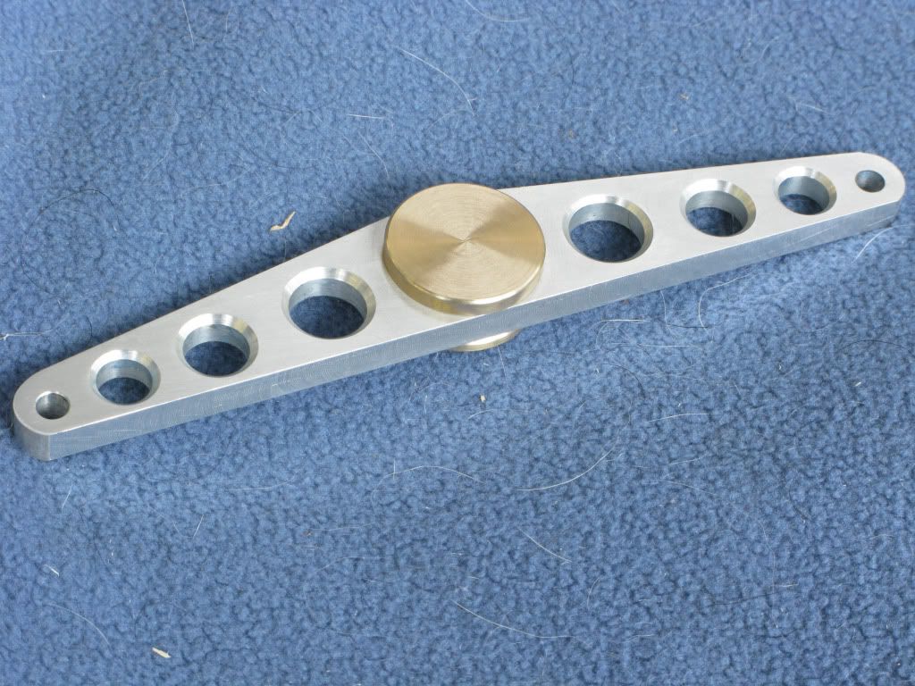
The next part I decided to make was the beam but whilst drawing it out I played around with different shapes and settled on this one. I originally thought that I would put a brass bush in the pivot point but eventually thought it would be better to make the beam and the central boss separately, that way I could do it in three parts and have the contrast of ally and brass as I had done on the flywheel.

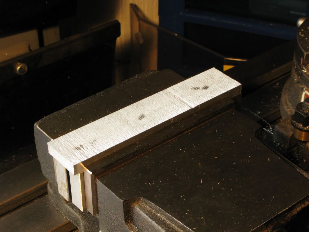
I cut an 8mm slice of ally from the 38mm square stock, on the band-saw, then faced both
IMG_0944.jpg
sides to the required thickness.

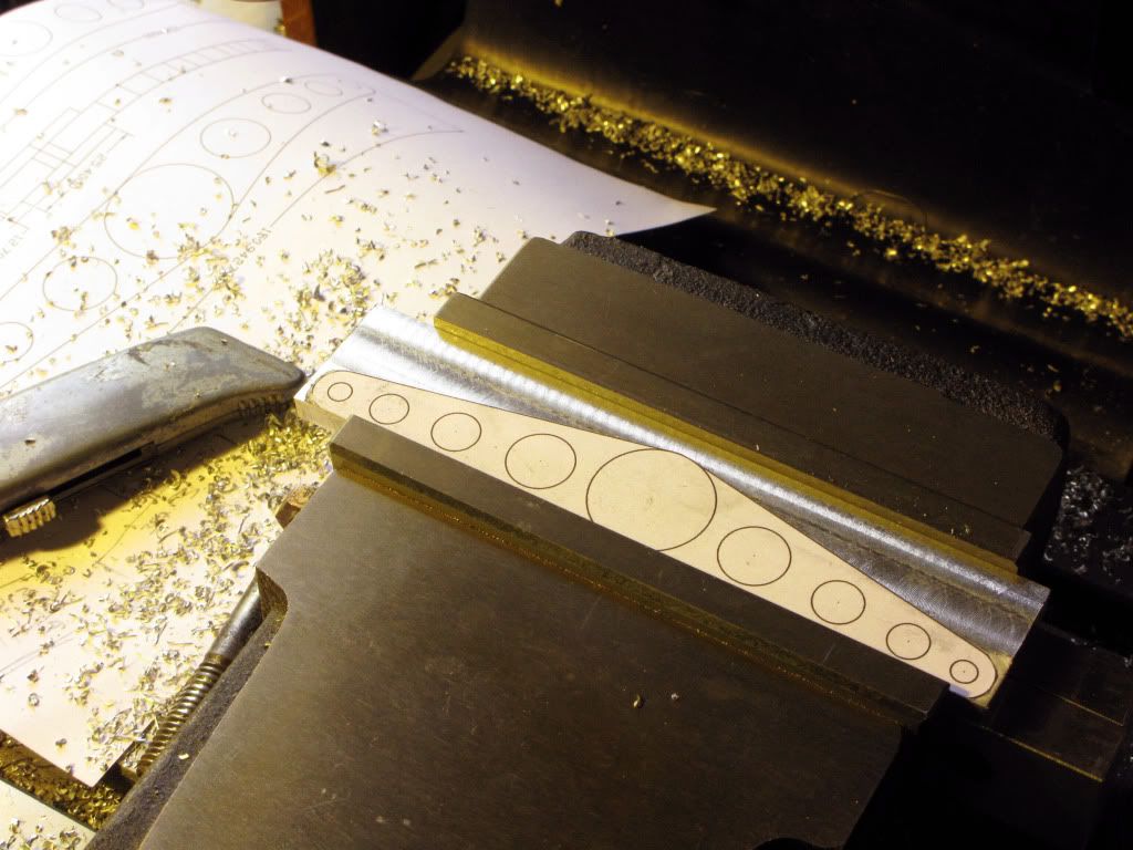
Attached a full scale drawing with double sided tape
IMG_0945.jpg


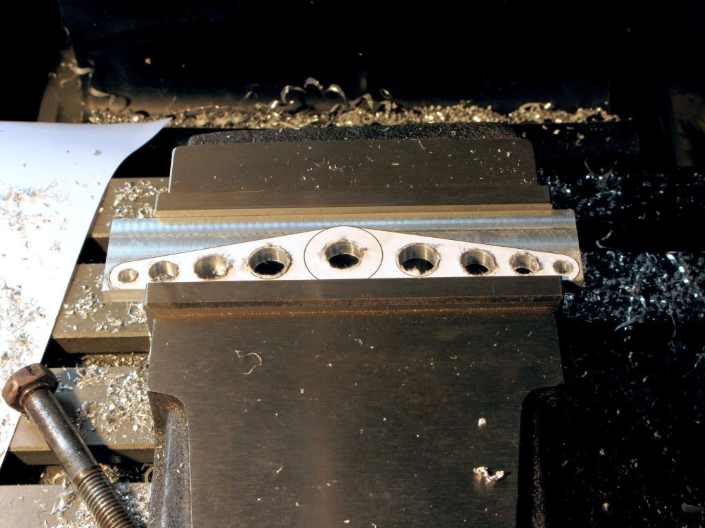
then drilled and countersunk all the holes, which reading from the left were 5mm 8mm 10mm 12mm and a 12mm centre hole for the split brass boss.
IMG_0948.jpg


I then used the band saw to remove unwanted metal, then milled the top profile and took a light skim off the bottom. No pics.

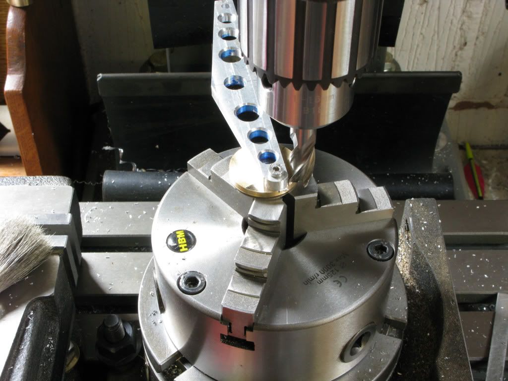
The rotab was set up to radius the ends
IMG_0981.jpg


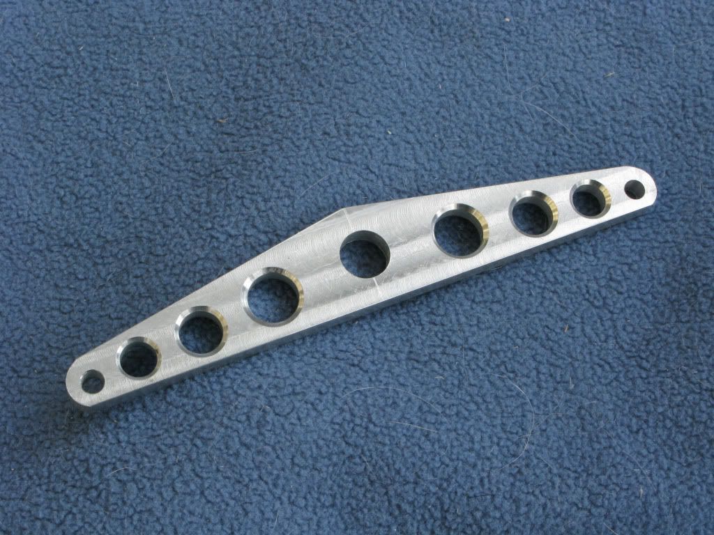
And here it is waiting for the brass bits.
IMG_0984.jpg


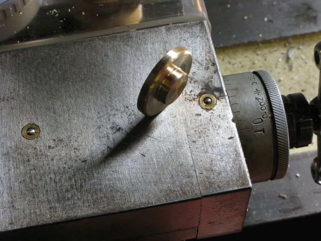
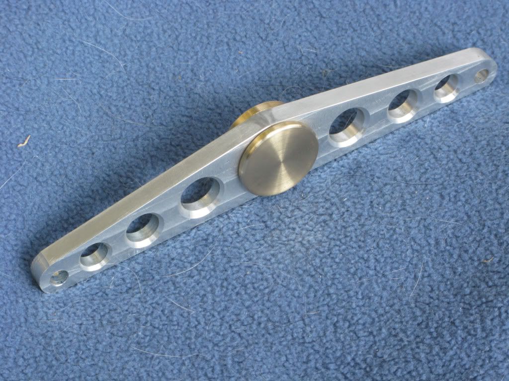
The two halves of the brass boss were made to be a light press fit into the beam and outer diameter was first chamfered then rounded whilst still in the lathe using a file
IMG_0989.jpg


IMG_0988.jpg


They were dry fitted into the beam which had been sanded with 400/600 w&d.
IMG_0993.jpg


IMG_0991.jpg


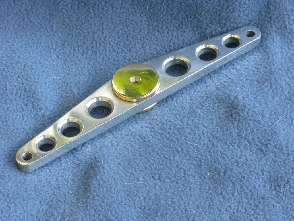
All components were then polished. The mating parts were cleaned using thinner, coated with red locktite and pressed together. The pivot hole was left un-drilled as I wanted to leave that until the column was done, then decide upon the size of pin to use.
IMG_1003.jpg


IMG_1002.jpg

 
Back
Top