Tony Bird
Senior Member
Hi,
A little while ago I did a thread on a steam powered model paddle boat seen here on the pond at Winterbourne earlier this year.
A video at: https://youtu.be/ZgTk3ePlhjE
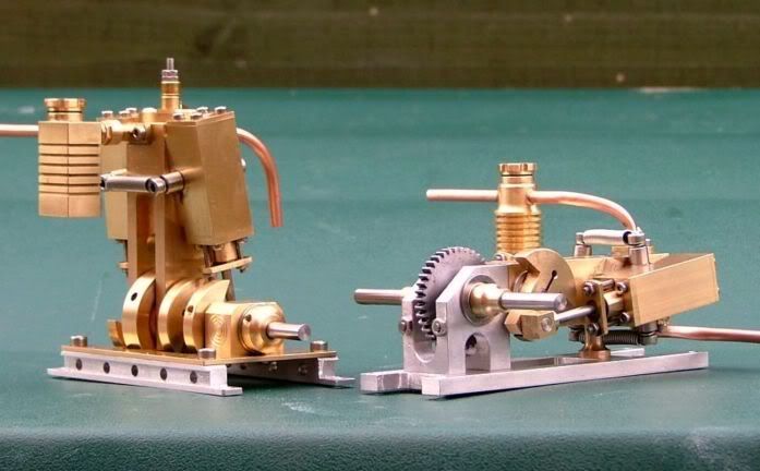
I was quite pleased with the performance of the model which uses one single acting oscillating steam engine driving the paddles through a gear box. It is quite exciting to control using rudder only and not being able to stop start or go backwards. Some time ago a friend gave me a lot of Mamod and replacement Mamod cylinders that are used on their locomotives; he said that he couldn't get them to work very well. So I thought I would try and get the cylinders to work and use them to make a prototype twin cylinder engine that would start, stop and reverse. The gear box to be used is the same design as is used in the paddle boat but with a lower gear reduction of 12:1 rather than 18:1.
I suspected that the cylinders would be too powerfully for the small hull of the paddle boat and in the event I was proved to be correct.

So it was decided to make a much smaller engine of a similar design, the cylinder size being a 1/4" bore and 1/2" stroke rather than the 3/8" bore and 3/4" stroke of the first engine.
The engine will be based on a small engine I designed years ago, this engine can be made single or double acting with bores of 1/4" up to 1/2", most built have been 5/16" bore all had a common stroke of 1/2".


The engine's column has been made of a light gauge aluminium square tube.

The port blocks and the reversing block with its valve have been made from some large brass angle that I have and was machined to thickness using a shellac chuck.

The small cylinders are fabricated in my usual way from some hexagonal brass rod and some K&S brass tube.


The K&S tube was soft soldered to its base and tippex (a correction fluid which contains chalk) was used to stop the solder contaminating the threaded hole.

The result of the first days efforts.

Regards Tony.
A little while ago I did a thread on a steam powered model paddle boat seen here on the pond at Winterbourne earlier this year.
A video at: https://youtu.be/ZgTk3ePlhjE
I was quite pleased with the performance of the model which uses one single acting oscillating steam engine driving the paddles through a gear box. It is quite exciting to control using rudder only and not being able to stop start or go backwards. Some time ago a friend gave me a lot of Mamod and replacement Mamod cylinders that are used on their locomotives; he said that he couldn't get them to work very well. So I thought I would try and get the cylinders to work and use them to make a prototype twin cylinder engine that would start, stop and reverse. The gear box to be used is the same design as is used in the paddle boat but with a lower gear reduction of 12:1 rather than 18:1.
I suspected that the cylinders would be too powerfully for the small hull of the paddle boat and in the event I was proved to be correct.

So it was decided to make a much smaller engine of a similar design, the cylinder size being a 1/4" bore and 1/2" stroke rather than the 3/8" bore and 3/4" stroke of the first engine.
The engine will be based on a small engine I designed years ago, this engine can be made single or double acting with bores of 1/4" up to 1/2", most built have been 5/16" bore all had a common stroke of 1/2".


The engine's column has been made of a light gauge aluminium square tube.

The port blocks and the reversing block with its valve have been made from some large brass angle that I have and was machined to thickness using a shellac chuck.

The small cylinders are fabricated in my usual way from some hexagonal brass rod and some K&S brass tube.


The K&S tube was soft soldered to its base and tippex (a correction fluid which contains chalk) was used to stop the solder contaminating the threaded hole.

The result of the first days efforts.

Regards Tony.