2" Fowler Traction Engine latest progress

Home Model Engine Machinist Forum

Help Support Home Model Engine Machinist Forum:

This site may earn a commission from merchant affiliate links, including eBay, Amazon, and others.
As everybody has said, it's absolutely beautiful. I grew up watching these things at steam fairs spending most of my time in the model section. I tend to take them for granted a bit when they are painted up and trundling around the ralley field, you tend to forget all the hard work that somebody has put into them because they looks so real. But this thread has once again made me realise how much work and craftsmanship is in there. It's stunning, the very thing that introduced me to this hobby - I wonder if one day I will ever be able to make one.

Well done Jason, thanks for sharing.

Nick
 
Wow!!

Fantastic!
I'm still amazed at the quality of work I see on this forum.


As said before WOW, that is very nice.


Ron
 
Jason, I've had an almost lifelong interest in traction engines. I really like the look of an English style engine with the flat spokes and large flywheels. With the quality of the work going into your engine I'm sure it will be very impressive when it's all polished and painted.
gbritnell
 
Beautiful build Jason. It is already stunning so I can hardly wait until it is finished and moving under it's own power.
Gail in NM
 
Hi Jason, great work on the build..George asked on the bearing adjuster on the big end, when you have a moment would you post a c.o.c.and explain just how it operates...I will have to make a similar one for the Corliss and cant seem to get my head round that bit.
All the best for now,
John.
 
Thanks for al the knid comments, will keep you posted on progress

John, The bearing adjuster works on the same principal of a folding wedge. As the adjusting nuts on the wedge are turned it will be pulled further into the strap and as it does so will become wider, this in turn will push against the split bearing and close up the hole effectively taking up any wear.

splitbearing.jpg


J
 
Thank you Jason, got the idea now...wonderful how a C.O.C. tickles the old brain cells better than the actual design drawings.
All the best for now,
John.
 

Awesome job Jason!

It looks great!
 
Great job! That is one nice looking engine.

Chris
 
Well it seems that the last month or so has been spent turning lengths of bronze and brass bar into an expensive pile of swarf as I have been working my way through the various bits of plumbing on the Fowler. All the parts still need to be buffed up but I will leave that until painting time.

First up were the two cylinder draincocks which have to be fabricated to get the correct angle.
PICT0147.jpg


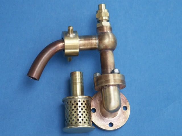
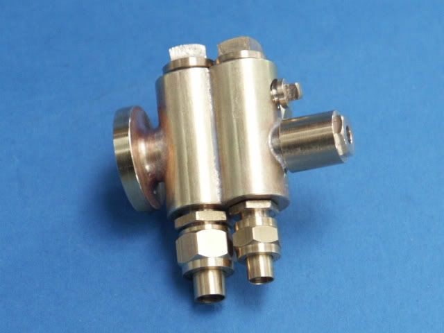
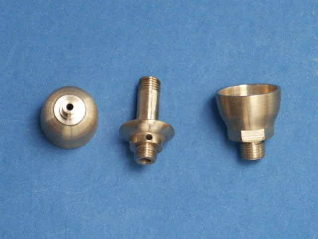
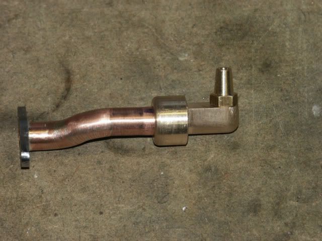
Next was the waterlifter, the ball turner was put to good use on the "T" joint and the elbow is fabricated. I went for a drilled tubular strainer rather than the gauze spec'd on the drawings
PICT0151.jpg


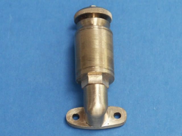
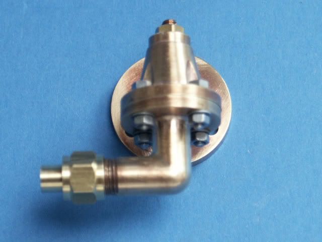
The displacement lubricator and pump clack were both similar fabrications
PICT0150.jpg

PICT0148.jpg


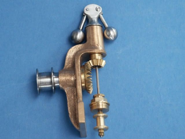
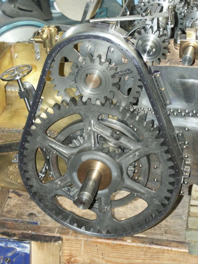
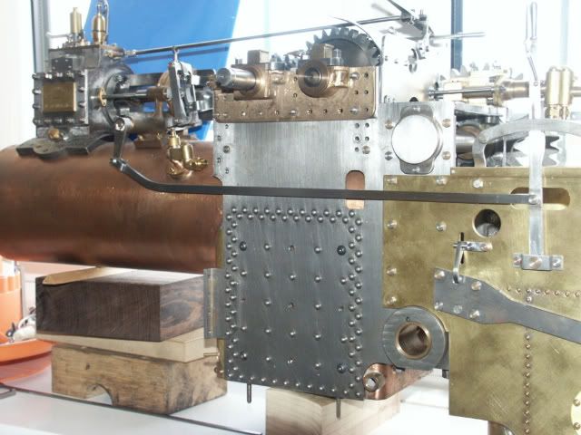
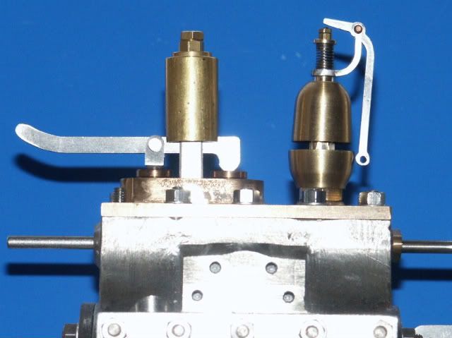
For a break from the pluming I then tackled the governor, balls are again turned from solid rather than joining commercial ones to the arms. I will probably up the 10BA grubscrews that hold the pully & gear to the horizontal shaft to 8BA as its hard to tighten then with such a small slot. Gears are from MJ and just need a little work as they are stock gears.
PICT0152.jpg


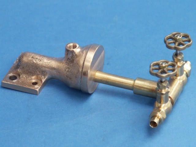
Back to the plumbing and the last casting left to be machined was the manifold, I intend to take the watergauge top feed from one of the bolt holes as the drawing has it off the manifold face which is now not allowed. Can't take credit for the globe valves they are from Steamfittings
PICT0154.jpg


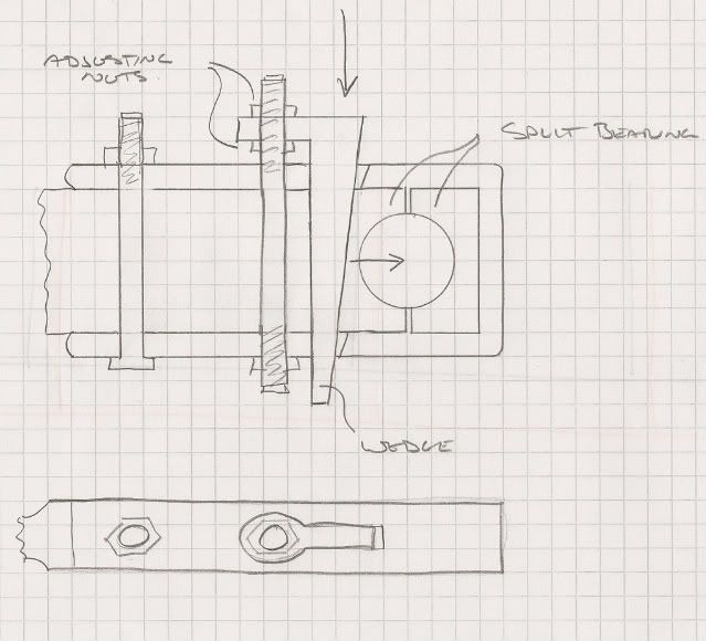
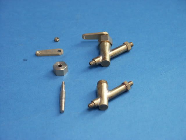
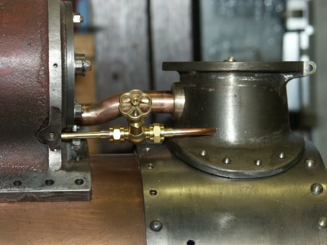
This is the back end of the pump, just need to do the tapered spindle for the tap.
PICT0155.jpg


The brass bits for the whistle are done, was just waiting for some 1/16 stainless rod for the valve which has now arrived.
PICT0153.jpg


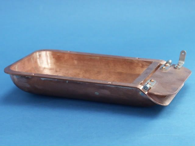
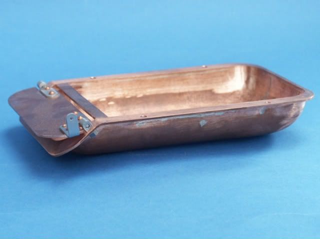
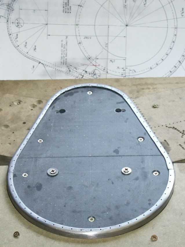
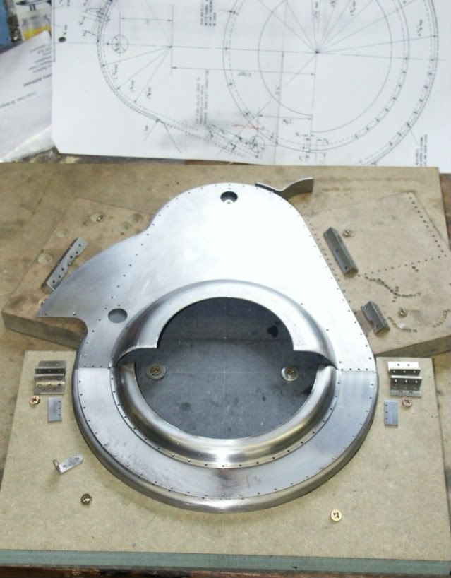
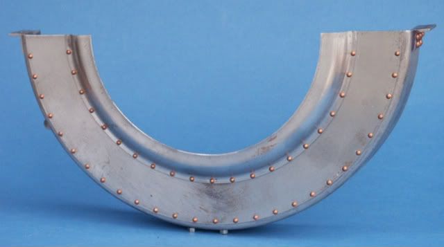
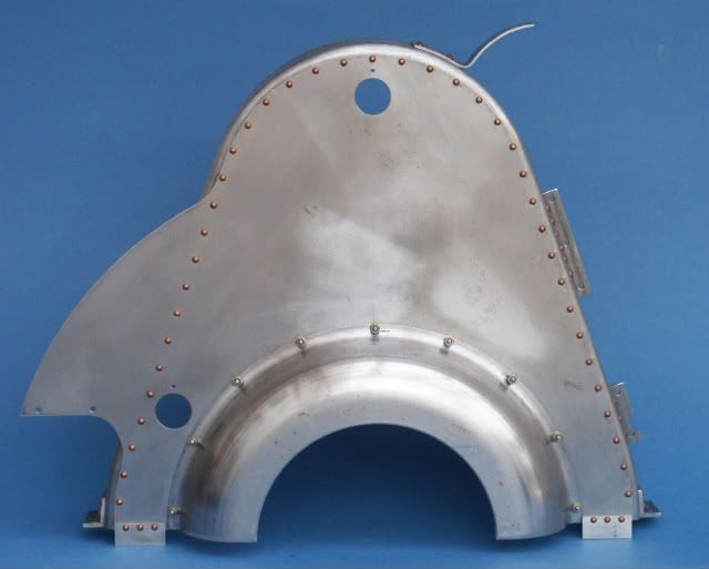
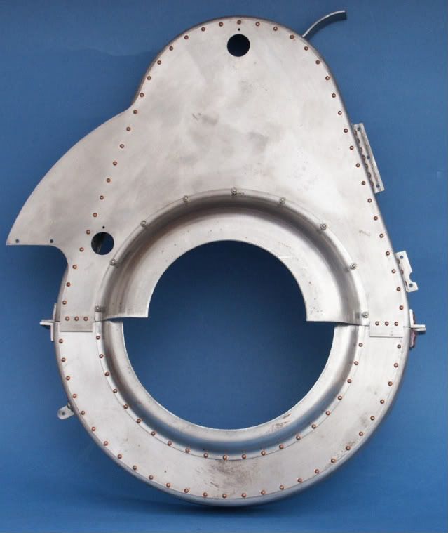
I also bashed out the ashpan over a hardwood former and silver soldered on the mounting flange. I opted for stainless steel hinges etc rather than the mild specified.
PICT0156.jpg

PICT0157.jpg


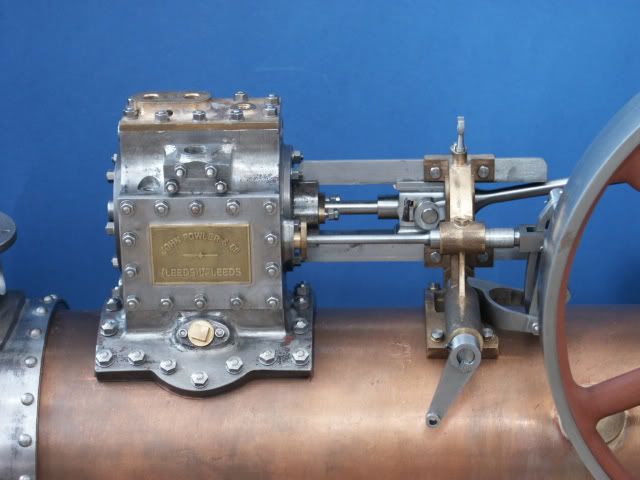
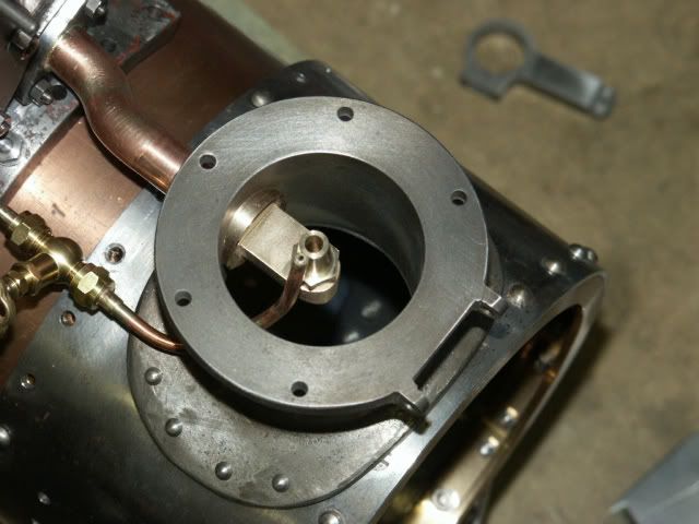
And lastly for this update the cylinder is now bolted to the boiler, I turned up bolts from stainless hex with a dimple on the end to look like studs.
PICT0158.jpg


Jason
 
zeeprogrammer said:
Absolutely awesome. Wow.
Thank you so much for posting those pics.

Right...quoting myself. Seemed appropriate as I don't know what to add.
That is some beautiful stuff.
 
Jason,
Beautiful! You're an inspiration.
Dennis
 
may I add my words here? ...well, I don't know what to say
awesome, gorgeous, a piece of art :bow:

thanks for sharing Jason
 
kvom said:
I must add Jasonb to my list of inferiority-inducing posters. :'( :bow:

For me, that list has many posters on it.

Beautiful work.

SAM
 
Superb work Jason, :bow: :bow:

Best Regards
Bob
 
Fantastic work Jason, being new to this hobby I just wouldn't know where to start to achieve your level of workmanship. I am totally blown away by it.

Nick
 
Can't believe its been so long since I posted an update on progress, must admit its been a bit slow as I've been sidetracked by a Hit & miss Engine. (see here for its build)

One of the major parts that have now been done are the gear guards, I don't much care for sheet metal work but was quite satisfied how they turned out. I made a former from MDF topped with Corian which is a very hard plastic and formed the outer edge around this.

PICT0084.jpg


Next the flat outer plates were cut to profile and drilled for the rivits.

PICT0086.jpg


This shows the outer shape being offered up to the engine to get the position for the various mounting brackets and cut outs. Anyone else building this engine should check the depth of the gaurds as mine came very close to teh final drive gear which required the backs of the rivits grinding down to clear everything.

PICT0083.jpg


And here they are complete with the two half round spinnings that are supplied by MJ.

PICT0178.jpg

PICT0177.jpg

PICT0179.jpg


The drawings show the exhaust pipe at 7/16" dia with a bent end to form the nozzel, in order to get this bend into the chimney base requires a 3/4" dia hole and some way has to be found to fill the gap. I deviated and turned a bronze elbow that screws onto the pipe and is a snug fit in the 3/4 hole, this also allows me to change blast nozzel sizes if need be. While at that end I walso did the blower pipe. The bends in teh actual pipe were formed following fellow A& builder Doug's method of multiple cuts almost all the way through the pipe then silversolder up teh gaps

PICT01472.jpg

PICT0146.jpg

PICT0145.jpg


The eccentric rods were drilled and reamed to length which allowed me to set the motion and determine the length of teh reversing rod which needed quite a bend to clear the injector clack that is not shown in the drawings

PICT0183.jpg


I also got the safety valves and whistle finished, does not make a lot of noise when I blow through it but it gets my dogs attention!

PICT0181.jpg


There are quite a few other bits and bobs done but nothing much worth taking pics of

Jason
 
Back
Top