1/3 scale V10, second project

Home Model Engine Machinist Forum

Help Support Home Model Engine Machinist Forum:

This site may earn a commission from merchant affiliate links, including eBay, Amazon, and others.
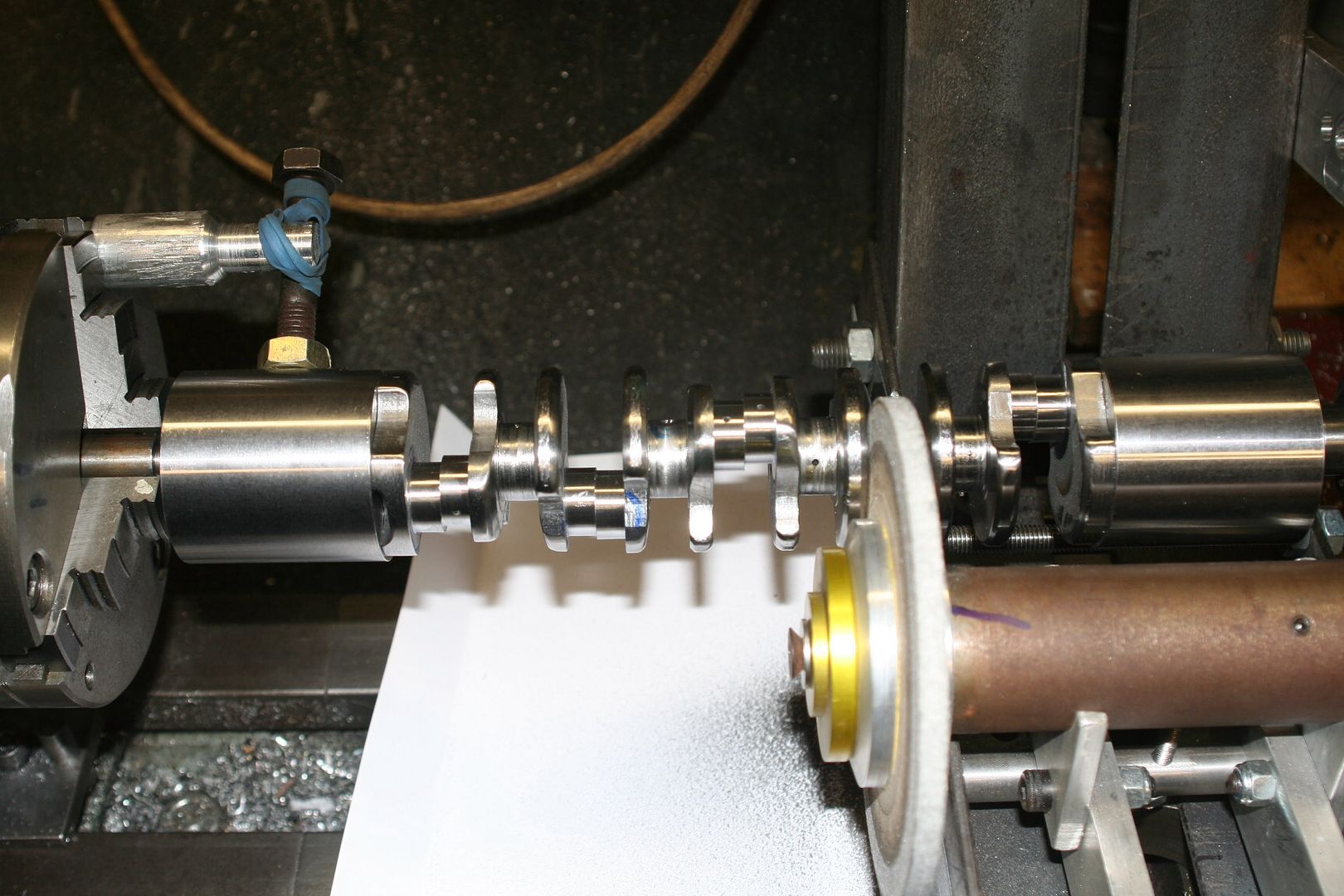
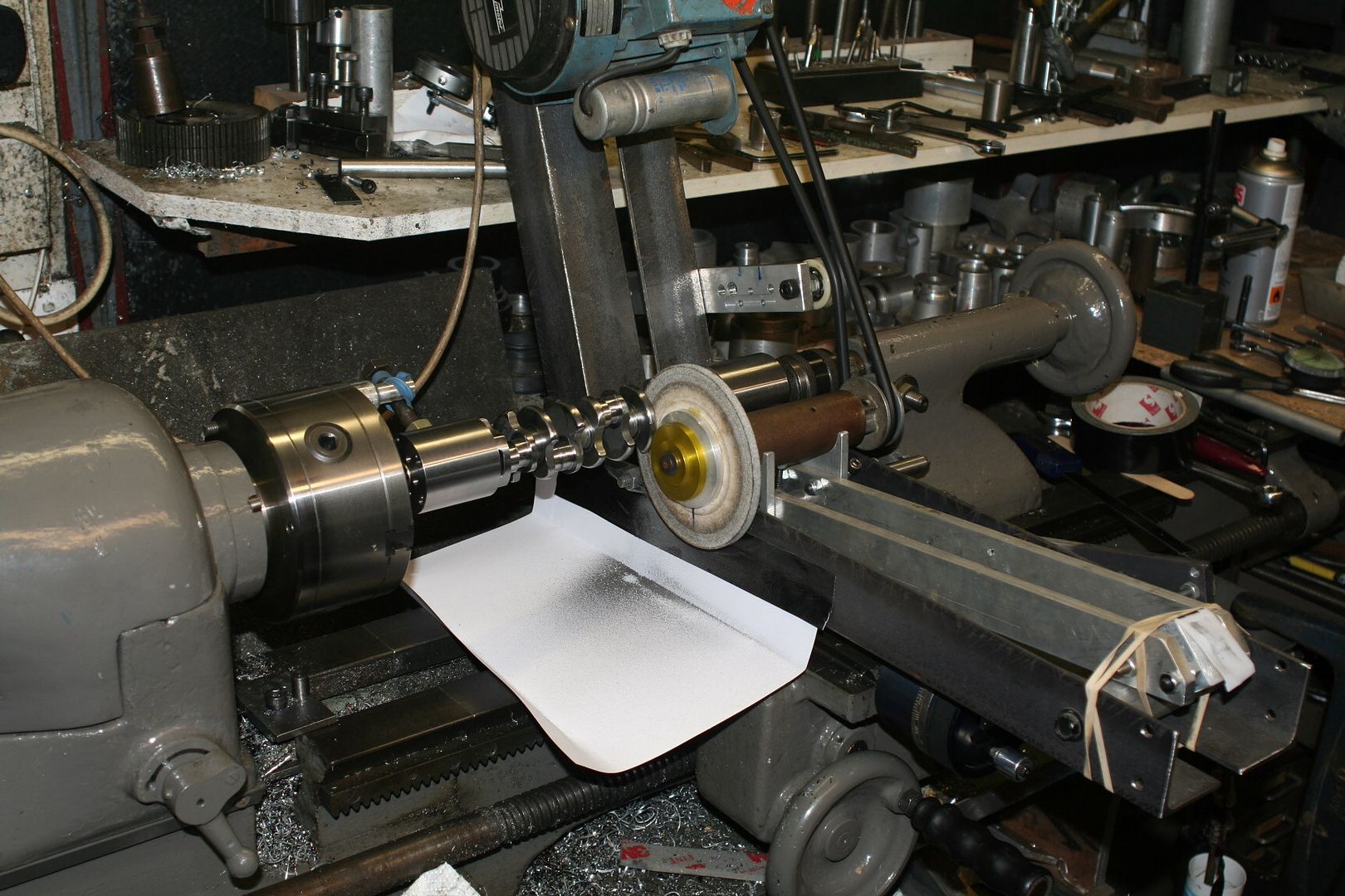
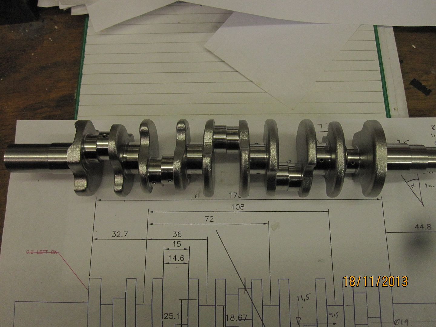
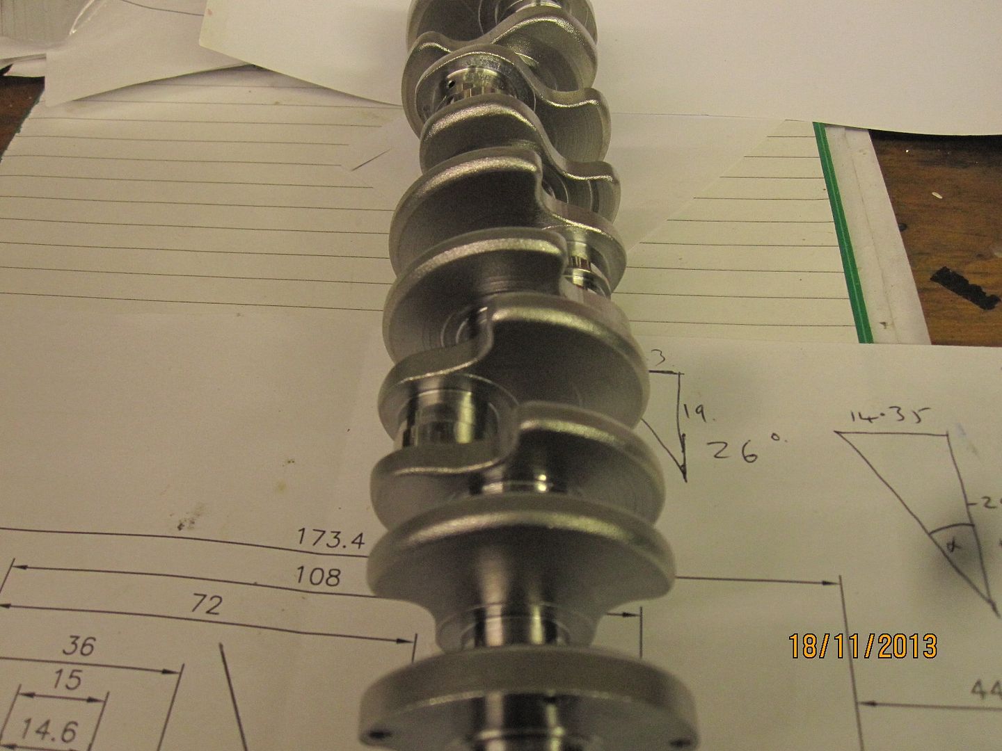
Started the crankshaft. I don't think the pics will be in order as I'm doing this on the ipad for the first time and it's all a bit weird at the moment. I made 2 ends first which have two sets of 5 locating pins. The big end journals will be split by 10 degrees as I want it to be even firing but don't want a 72 degree block, as that makes the top a bit too narrow to fit all the manifold bits.
With a 10 degree split journal I can have an 82 degree block vee angle.
Hope that makes sense
Hmmmm....sorry I can't figure out how to get the pics up on this ipad, I'll do it at work tomorrow.
 
Keith;
Thanks for the clarification on the surface finishing.
Cheers Garry
 
Top work Keith, as usual the standard of your finishing is inspiring.
To add a little to the turbo discussion, you might want to take a look at the design of some dental air turbines. They use a pelton wheel and some of the fastest out there are operating at over 1 million RPM. The wheel sizing would be in the right ballpark on scale grounds, even if this wasn't necessarily correct for the engine's requirements from a pressure/flow standpoint. It's also worth considering that as the surface area to volume ratio on these small engines is so heavily in favour of area, cooling the turbo assembly might actually be a bit more straightforward and simpler than what is used in full size applications. I really hope you are successful in the turbo development. You have done the ECU control and the fuel injection, so if anyone has the skills to pull it off...
 
I suppose the first thing to do with the turbo would be to work out the amount of gas coming out of the exhaust and convert that to a cfm and pressure so I can use my compressor to do some testing with different types of turbine wheel/housings.
It's probably 12 months away when I'll start that side of things, but it would be nice to have some idea of what to try, before then.

I'm having another go with the ipad with a couple of pics. Done more work on crank, and drilled the oil holes.
Unfortunately I broke a 1.5mm dr l in one hole just as it broke thro. I can't get a straight line of sight from the other end to punch it out, so it's stuck at the moment.

Worst case scenario is I can get it sparked out, but that's a last resort.

[/URhttp:/L]


[URL=http://s28.photobucket.com/user/keith5700/media/image_zps52455270.jpg.html]
 
I have sympathy with you on the drill breakage and the easiest and safest is the spark erosion way.
Hows about gearing up a small impellor in a timing case set up at 1:10 to start with giving 10x engine speed at the impellor illiminating the volumetric losses. It coukd be done in a very small case close to the block / intake manifold
Nice work so far.
 
Last edited:
Hey Keith!

Your work is amazing and inspiring! Great work with the V8.
 
Got the crank finished. I ended up milling most of it with the dividing head. It worked a treat. I milled it down to plus 10 thou and then ground it to size with the grinding attachment I knocked up for the V8 cams. I'm a big fan of grinding now. If I can get another small lathe I'd like to make a permanent grinding machine.

Anyway, after grinding I polished the journals and steel shot preened the webs. It doesn't really need preening but it does a great job of covering up the file marks

image_zpsc9bcbbc3.jpg
[/URL]

image_zpsb9352858.jpg
[/URL]

image_zpsf211f53c.jpg
[/URL]

image_zps077b6f45.jpg
[/URL]
 
Only in my dreams could I do this kind of work. Makes my project look like a tin can :|
 
2 simple questions:

1. How did you protect the journals frm the steel shot?
2. What method did you use to polish the journals?

Superb crank.
 
When I grow up I want to be able to do this level of fabrication !

I have a question that is may be obvious to everyone else, what is the purpose of the large bolt with a brass colored nut and what looks like a standoff that is touching the lathe chuck in the first two crank grinding shots? It also has something wrapped around it.

Just trying to understand the method and learn...

Pete
 
He's turning the crank between centres at that point. The crank isn't actually being gripped by the chuck, the bolt is acting as a drive dog.
This is the best way to get the part rotating on a repeatable axis even if you need to remove and replace it multiple times.
 
How are you going to balance the crank shaft after hand filing the webs?

John.
 
Ok thanks LongRat, I see that now !
Pete
 
Journals are protected from shot by cloth tape, or duct tape. Not worth tooling up for a one off.
Polishing was done in the lathe with strips of emery paper. 600 grade first, then 1500, then 2500. I may do another polish with the felt wheel later.

I'll try and take a pic of the offset grinding of the big end journals.

The filing on the crank is just to take the corners and edges off, so won't affect balance too much. The plan is to build the rotating assembly up and dynamically balance it on the bench.
I have done this before on a full sized chevy v8. It will need a smooth drive, to about 2000rpm, spring suspension for the block and a couple of accelerometers feeding my oscilloscope, to show the out of balance. Then it's just trial and error, adding weights to the flywheel and front damper.

The weight of the piston rings needs to be glued to the piston tops.

This is probably 6 months away, but should be interesting.

I didn't balance the v8 and it turned out ok, but the v10 is a big lump, so will need balancing. It may turn out to be unbalanceable, in which case I'll fit a couple of balance shafts.
 
The plan is to build the rotating assembly up and dynamically balance it on the bench.
I have done this before on a full sized chevy v8. It will need a smooth drive, to about 2000rpm, spring suspension for the block and a couple of accelerometers feeding my oscilloscope, to show the out of balance. Then it's just trial and error, adding weights to the flywheel and front damper.

The weight of the piston rings needs to be glued to the piston tops.

This is probably 6 months away, but should be interesting.

I didn't balance the v8 and it turned out ok, but the v10 is a big lump, so will need balancing. It may turn out to be unbalanceable, in which case I'll fit a couple of balance shafts.

Most interesting, is it more accurate that setup vs balancing it on a prop balancer?

Coming along nicely!

John.
 
John, from my understanding of it, balancing the crank alone wouldn't achieve anything useful. The crank needs to be balanced with some dummy weights fastened to the journals, to represent the mass of the conrod and piston, etc.
This would normally be all of the rotating weight, ie the big end of the rod, plus half the reciprocating weight, which is the rod little end, piston, pin, rings, plus a little bit of oil.

With this lot bolted to the crank it can then be dynamically balanced.
Static balance on a prop balancer still wouldn't be any use, as the crank needs balancing end to end as well, unless it's a flat plane crank, I suppose.

The other way is to build the bottom end up and then dynamically balance it spinning in the block. Theoretically this must be the most accurate way, and easier too.
The only fiddly bit, apart from sorting out the accelerometers, etc, is to glue dummy weights for the rings, onto the piston crowns first.
 
I've not seen this method of making the bearing shells too often, so I decided to photograph every step.
Apologies if everyone already knows this stuff.

First step was to rough turn and bore the phosphor bronze bar.


Then the tube was split


And then soft soldered back together


the new tube was then turned to be a tight fit in the rods, and parted off.


each bearing was then bored to about minus 10 thou' whilst still soldered together


then the interesting bit..boring the bearing to size. i have desoldered the 2 halves before this step, and assembled the rod as it would be on the crank


On the V8 it was a nightmare to get the bearing shells to stay in place whilst assembling the bottom end, so I decided to pin these shells. I can't really recommend this as it took forever to sort out. I'm glad I did it but would probably think of another way next time...


Latest posts

Back
Top