1/3 scale V10, second project

Home Model Engine Machinist Forum

Help Support Home Model Engine Machinist Forum:

This site may earn a commission from merchant affiliate links, including eBay, Amazon, and others.

keith5700

Project of the Month Winner!!!
Project of the Month Winner
Joined
Apr 3, 2011
Messages
192
Reaction score
305
Right, here we go again!
I've decided on a V10 this time, just to be different.
And I'm going up a scale, as with the V8 everything seemed to be just slightly too small to make a proper job. Maybe my eyesight is going, or I need smaller fingers.

Bore will be 1", capacity about 125cc.
I want a 90 degree block, but even firing, which means a split journal crank!
Not solved that one yet, but should be doable.

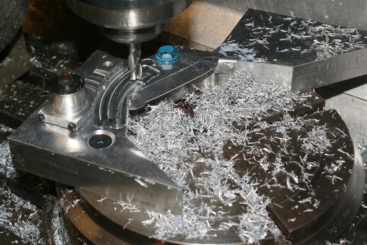
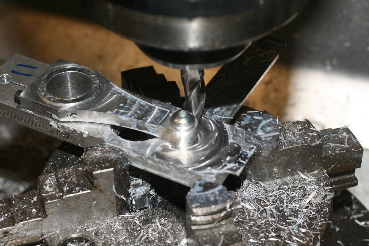
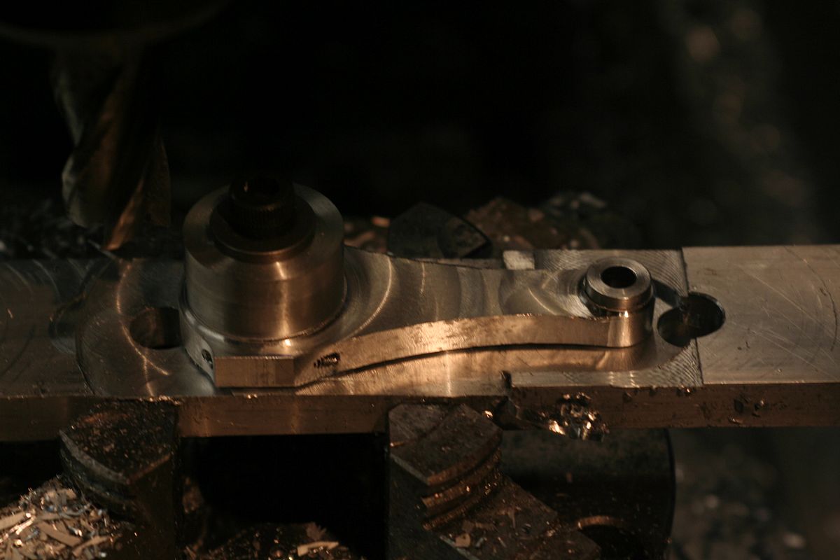
Not too much design work done yet, but I've started with the boring bits, which is conrods, pistons and crank, as they'll be pretty standard whatever the engine looks like.

I do know now, after the smoking issues on the V8 that I'm going for 3 rings on the pistons. 2 above the pin and 1 below. I'm also making the rings a bit thicker and wider than last time, to get a bit more sealing. This is on top of the scale factor of course.
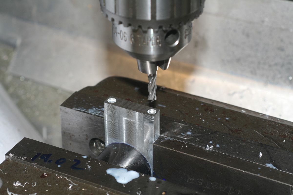
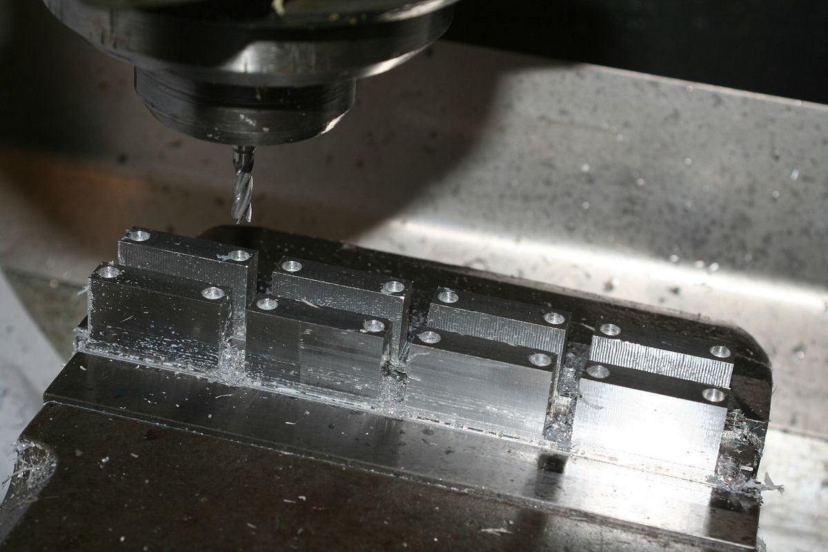
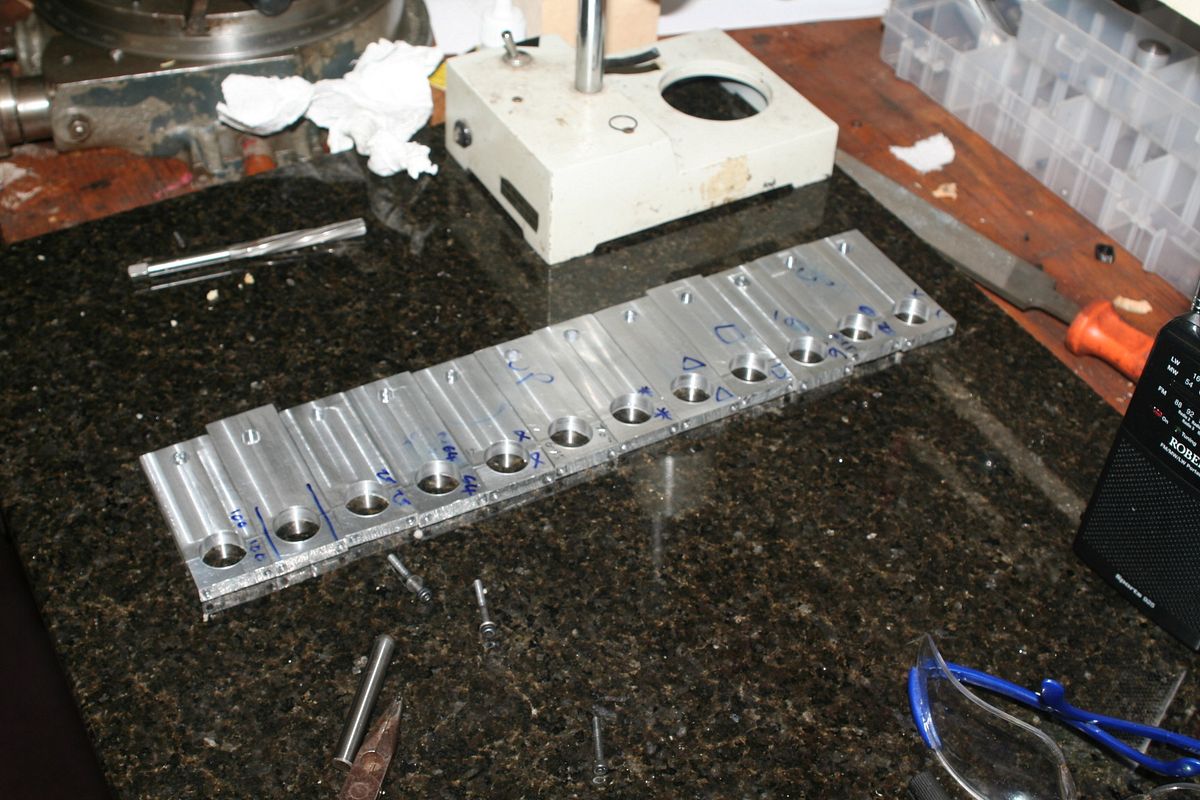
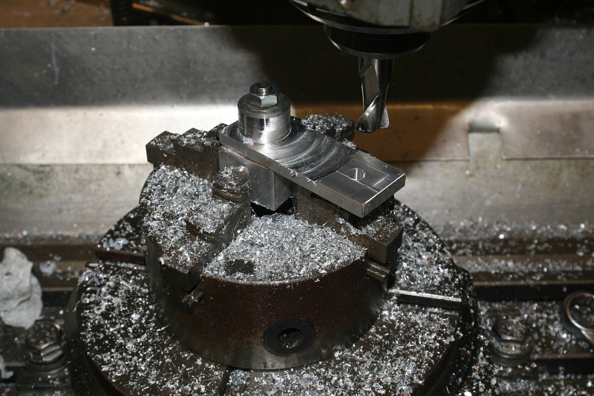
Anyway, rods first:-


I am sure all the usual suspects will be along for this ride as well. ;)
 
Keith,
Are you modeling this V10 after anything in particular or making it up as you go?
Art
 
Art, I don't really know what the engine will look like yet, or what sort of induction system I'll use. My problem is I only get about 20mins a day on the cad at work, so I start with stuff I know, like conrods, and the rest just follows.

It would be great to sit down for a month and draw everything out first, but there's no chance of that.

The v8 always seemed like a compromise, fitting stuff round other stuff, and bits were always interfering with other bits. Hopefully this time I can do a bit more planning before cutting metal.

Oh, I would like twin turbos, but have yet to research if any useful boost could be created at these sizes. Just 2 or 3 psi would do.
Cheers.
 
Righto you got me interested with your twin turbo . I don't know but I always thought that most high performance engines still only ran 5 psi maybe 7 psi boost. Your heads will have to be good and tolerances very tight even at 2-3 psi boost good luck I will watch with interest and if I am mistaken on my high performance data someone here will put me straight. Heavy truck engines run up to 30 psi and I have had 1 that boosted to 42 psi before derating after a mechanic altered the wiring to lie to the computer.
 
I don't think a turbo is practical at this size. Google for radial flow compressor design. Even a turbo for a 1L engine is 32mm in diameter and needs to spin 120,000RPM to make 3PSI (Garrett GT06).

Greg
 
Actually 120,000 rpm is normal for tubos large and small and still deliver meaningful boost. I think the hardest part will be balancing the impeller so it won't self destruct.

Cheers,
John.
 
Hello Keith,
I was reading your other engine build and had a thought regarding the smoking on that one that might relate to this new build.

On the other (amazing) engine, you ran it with no air intake restriction, and there was no smoke. With an air intake restriction, there is smoke. This leads me to believe that the vacuum of the air intake tract whats pulling the oil into the engine, most likely around the intake valves.
If it was really the oil control around the piston, smoking would not change with the induction change. Pressure in the chamber and crankcase are the same in both cases.

Is this new engine going to have a conventional valve arrangement with valve seals?
 
Actually 120,000 rpm is normal for tubos large and small and still deliver meaningful boost. I think the hardest part will be balancing the impeller so it won't self destruct.

Cheers,
John.

Yes normal RPM for large turbos, but minimum for GT06. Look at the map for the GT06. It tops out at 300k. The GT-6041 at 141mm diameter starts working at 28k and tops out at 78k. The smaller the turbo, the faster it has to spin to be useful. The GT06 is listed at 0.1-0.5L, but 25-80HP. Turbos require good flow matching. Designing a turbo requires much more. So with a twin turbo arrangement we are talking 60cc on a turbo and efficiency of the turbine and compressor will be so low as to make things difficult. Tiny turboshaft engines have been built, but nothing exists in production. Designing a turbo this small without CFD, I think would be a waste of time without a lifetime of experience behind you.

Greg
 
At the moment I just have a wish list of stuff I'd like on the new engine. I don't anticipate making another one after this, so this has got to be the very best I can manage, given my equipment and cash available.
Twin turbos are on the list, but they have to work, in a fashion, rather than just for show.

It may be impossible however to get any boostout of them. In which case I'll try a supercharger, but I can't think how to fit this in at the moment, as I'd like all the top end free for a nice induction system.

I'd also like 10 x injectors and a dry sump.
Any other suggestions considered.

Oh, and valve stem seals.

Finished the rods for now anyway.


I made a wooden engine as I thought it might look a bit bulky, but I think it's ok.

 
Keith;

Go cat go! Enjoyed the V8 build and looking forward to the V10 build. If the twin turbos don't pan out how about doing the supercharger like they did in the early drag racing and Bonneville salt flat racing days (AKA Potvin setup) - run the supercharger right off the end of the crankshaft and plumb the air up to the cylinder heads, frees up the top end and you get your room for injectors;

http://www.jalopyjournal.com/forum/showthread.php?t=463034

Cheers Garry
 
The the main reason turbos spin faster or slower whether big or small is for throttle response and maximum power for the engine size. Not useable efficiency for engine size. There is efficiency losses and gains for various applications using slower or faster rpms but it's not dictated primarily from engine size but mainly by application.

Cheers,
John.
 
Last edited:
John, that is simply not true. Turbo size is primarily dictated by flow and pressure requirement. A designer can opt to install a smaller turbo for less lag and less peak power, or larger for more power and accept the lag. Mulitple smaller turbos make big power with less lag with the associated cost. This says nothing about how the compressor wheel itself operates.

Once you know how much the turbo should flow, you size the turbine and compressor wheels (if you're designing the turbo and not buying off the shelf). The turbo diameter is very closely linked to the volume flow and pressure output with RPM. An oversize turbo will surge if the engine can't flow what the turbo is offering. A small turbo simply won't make much power. When you get to the aerodynamic design of the compressor wheel, you'll find that as the flow volume is reduced the best course of action is to reduce wheel diameter. Reducing wheel diameter reduces pressure at a given RPM. To make pressure RPM has to increase. So smaller turbos run faster than larger turbos. This is very obvious in turboshaft engines which are just turbos with a combustion chamber rather than a piston engine gas section. The smallest commercially available turbine engine for RC models is a Kolibri T-32 which uses the Borg Warner KP-31 compressor wheel. This engine runs at ~250,000 RPM at full power and idles at ~60krpm. A large turbine in the model class range is the AMT Nike, at 176Lbs of thrust. It idles at 20k and full power is 61kRPM.

The GT-06 and KP-31 are the smallest production compressor wheels out there. Anything smaller needs to be designed and built, both the turbine and compressor section. As size decreases airflow effects reduce efficiency.
 
Keith;

Is the method of finish on the con-rods the same as you applied to the cam covers on the V8 ? ;

"Then into the hand cabinets for a blast of fine glass, then a blast of 170 steel shot, at low pressure, say, 16psi."

I assume this was done in an industrial setting. Is there a "home shop" method of accomplishing something "somewhat similar" without spending a ton? At least creating a matt uniform finish?

Thanks Garry
 
I know all that and I stated it in my post that, though not specifically, but what my point is I think you can still have a turbo that turns slower so it is in realm of the home machinist.

I have never heard of engine size sollely dictating the rpm of the turbo. Everywhere I read about the subject there is the smaller turbo for faster spool times, biggest turbo a engine can spool for max top end power ect. Perhaps you can forward a link to explain this.

I'm designing a engine myself and spend a large amount of time researching about engine technologies so I can design the best engine I can.

I take no offence in what you say and I hope I haven't rubbed you the wrong way, if I did I opplogise.

Cheers,
John.
 
I'm interested in the finish that you achieved as well, looks like shot blasting. Do you achieve this in a home setup or do you have somewhere else you go to do it?

Paul.
 
Garry, the finish on the rods is done by hand in a blast cabinet at work.
The rods were finished using a ceramic media, but only because that's what was in the machine at the time.
The finish from glass beads is pretty much the same.

I have done similar jobs at home, just using my compressor and a cheap hand held sand blasting gun. Uses a lot of air though.
If I didn't have access to this stuff at work I would make a small steel box, with a glass top, and a couple of armholes in the front, and
just do it at home, with glass bead media.

The cam covers were done in the same way, but with a steel bead media, before anodising. I tried anodising over the glass bead finish, but the surface becomes a bit powdery after anodising.

You can buy a small blasting cabinet from £160 upwards in UK. but I reckon you'd need at least 10cfm compressor, or a big tank.

I can't join in the turbo conversation at the moment as I have done very little research, other than to suspect that it may not be viable at this scale.
 
I love the finish the blasting gives, but have no room for a cabinet at the moment.

I didn't say it was matching turbo RPM to the engine. I don't know a lot about designing radial flow turbomachinery, I studied axial flow design for a project a while back, but know enough to understand the characteristics of radial compressors. If you want a technical source any engineering reference on the topic will give you the information you need. To me the the relationship of pressure, rpm, and diameter is obvious in the maps. http://www.turbobygarrett.com/turbobygarrett/turbochargers Compare the three to see what they look like. Scale factors come into play which reduce efficiency as the turbo gets smaller. The small GT0632, Ø32mm, mentioned above manages 68% efficiency, the GT6041, Ø141, 80%. That may not seem like much ,but consider that the second smallest GT1241, Ø 41, only 9mm larger in diameter operates at 76%. You see that things go downhill quickly as size decreases.

I do understand what you mean about trading spool time for power. I was thinking street cars, but obviously turbo applications go all the way to drag and tractor pulls and other places lag isn't a significant factor.
 

Latest posts

Back
Top