
You are using an out of date browser. It may not display this or other websites correctly.
You should upgrade or use an alternative browser.
You should upgrade or use an alternative browser.
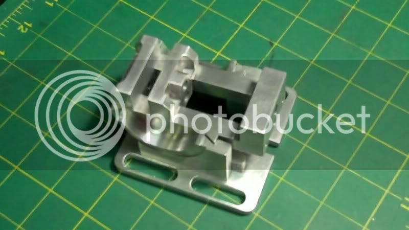
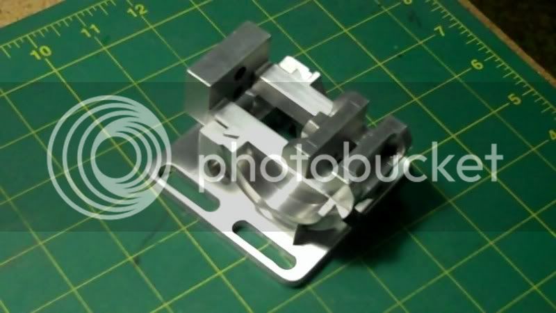
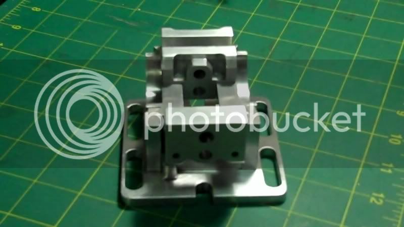
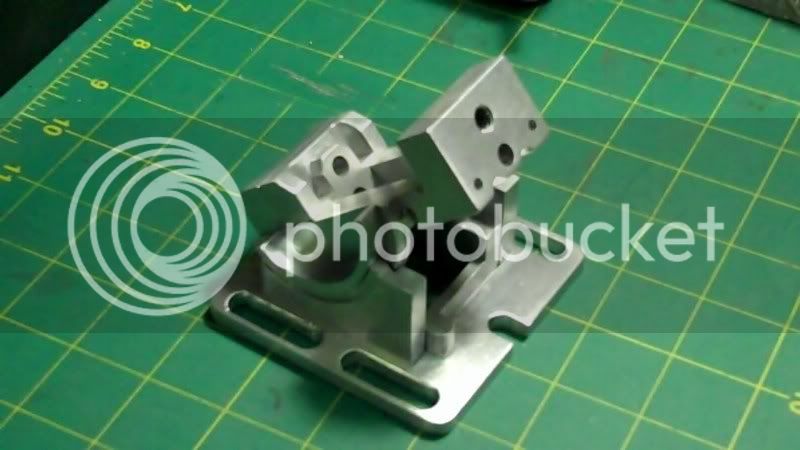
1/2: scale model of my angle vise build
- Thread starter hobby
- Start date


Help Support Home Model Engine Machinist Forum:
This site may earn a commission from merchant affiliate
links, including eBay, Amazon, and others.
- Joined
- Dec 5, 2009
- Messages
- 510
- Reaction score
- 47
Steve, Kel, George,
Thankyou gentleman, for the kind compliments.
and for following along in this thread.
----------------------------------------------
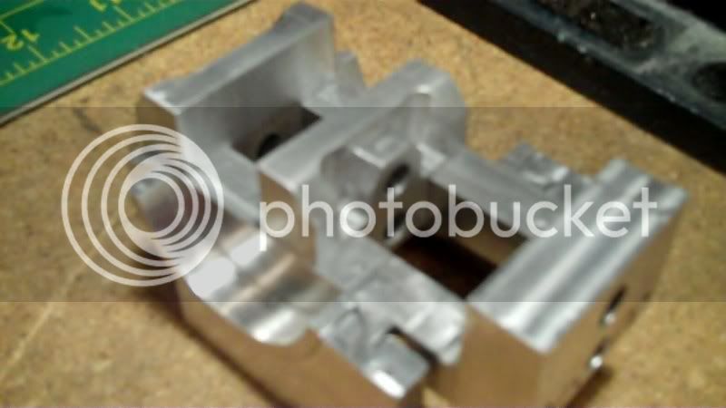
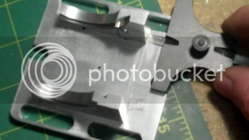
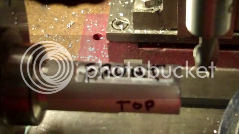
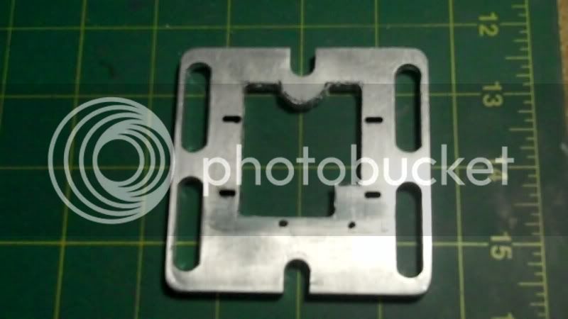
This weeks progress, doing a little each evening, for the last couple days,
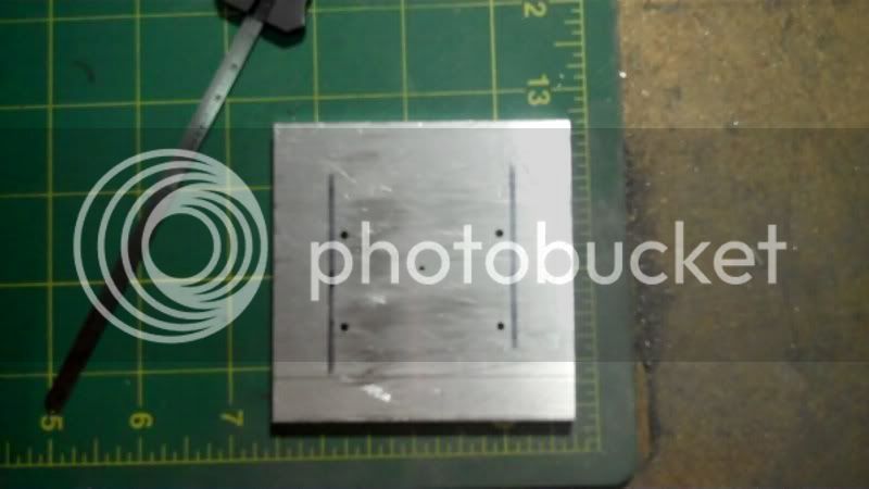
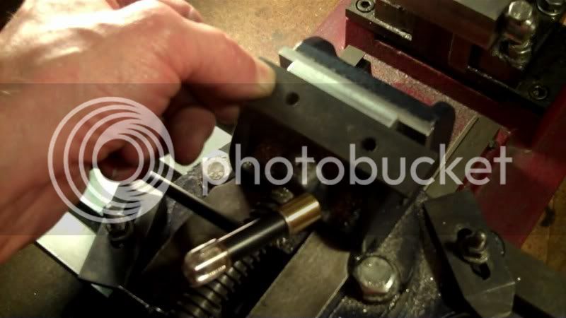
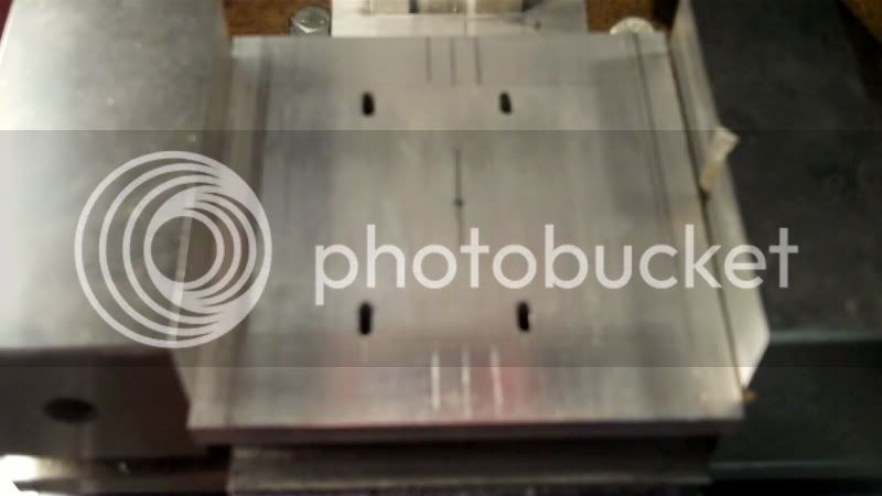
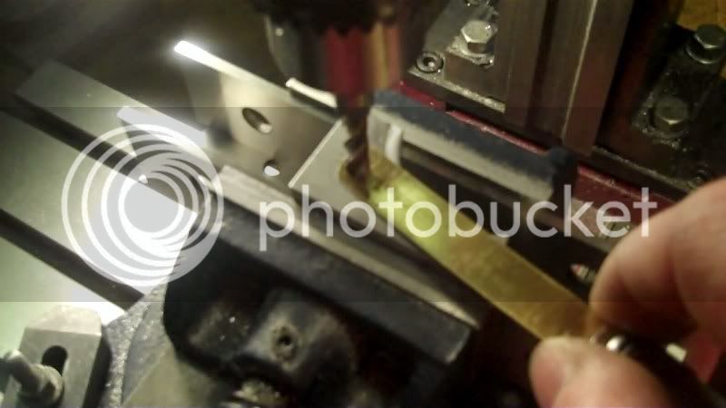
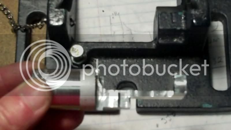
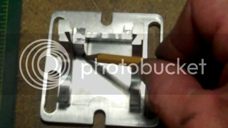
it was now time to start working on the moveable jaw, I layed everything out from center of the workpiece,
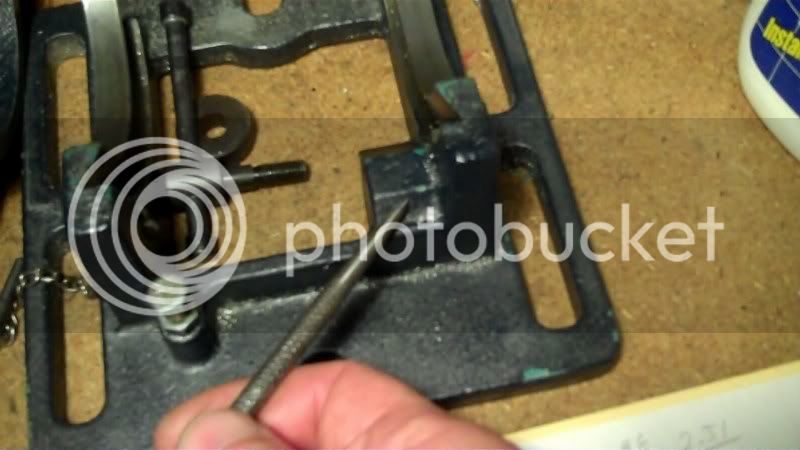
and now I needed away to keep everything lined up, so I used my reamer, which was used to ream these holes, as the lineup bar.
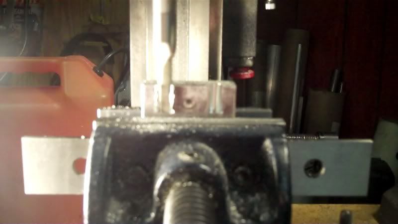
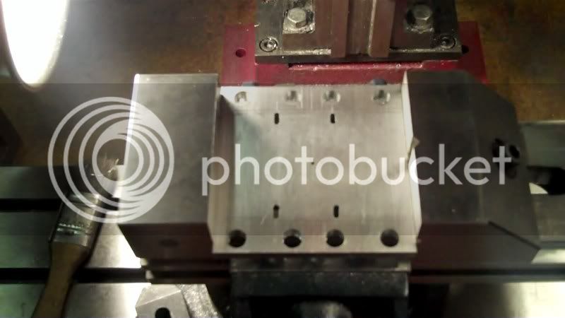
then I clamped the moveable jaw next to the fixed jaw to line up and transfer a centerpoint, for the nut portion on this jaw, to be drilled at.
drilling and tappping, for this nut portion,
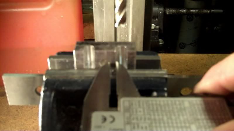
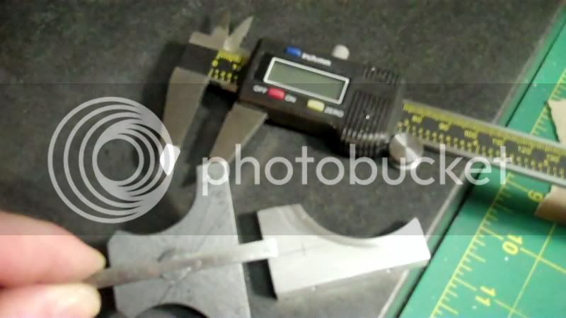
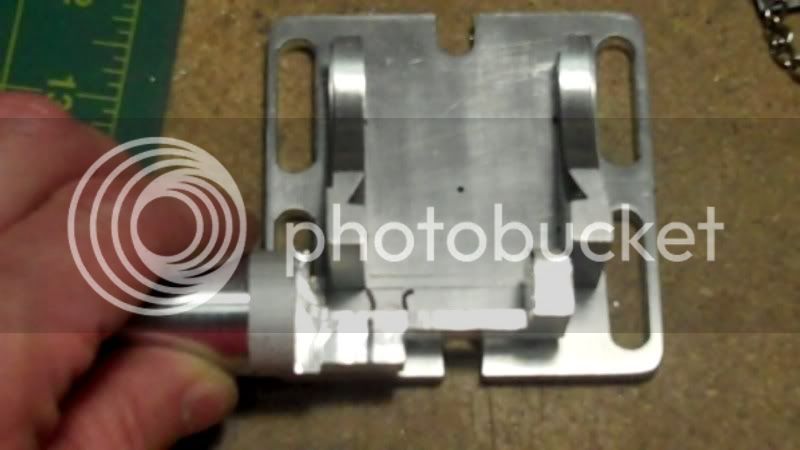
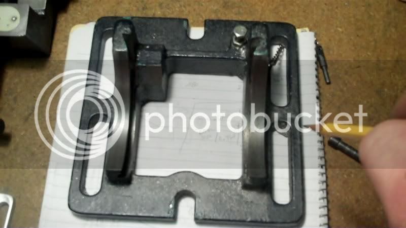
again to keep visual perspective on the workpiece, I did all machining from edge references, rather than center. As I did before, this ensures that features will be very close to mirror images from one side to the other. I could do it all from centerlines, tot, but this seems to be better choice at this point.
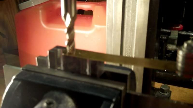
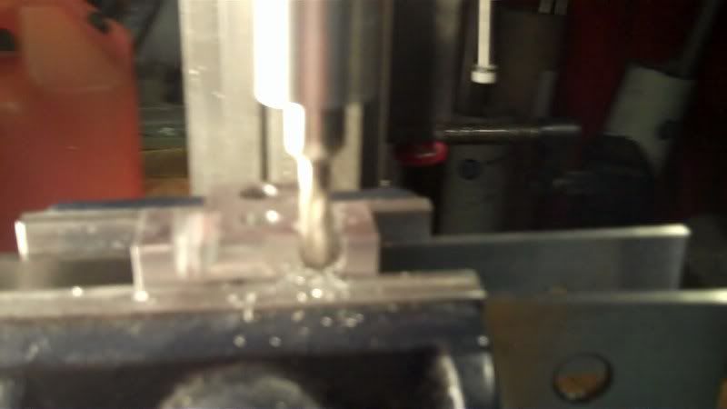
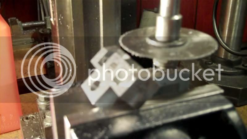
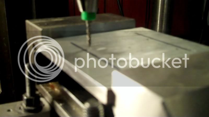
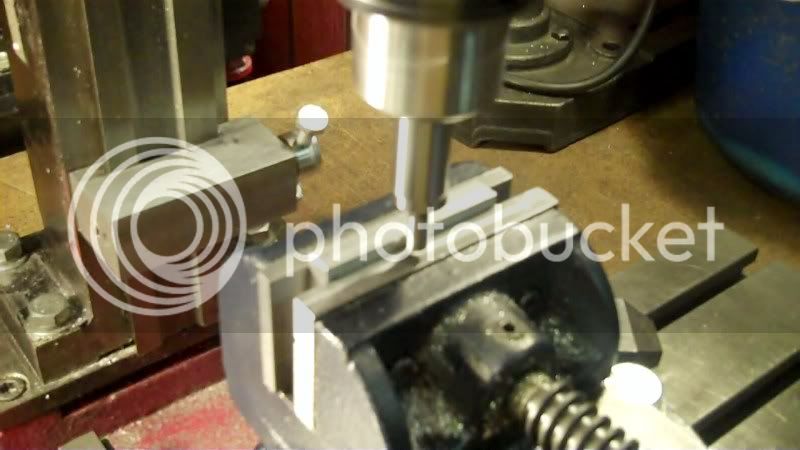
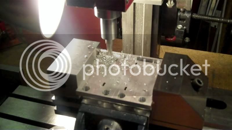
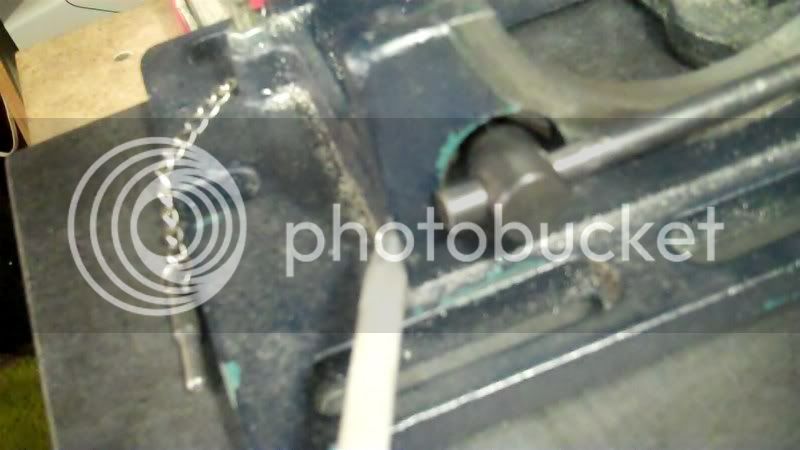
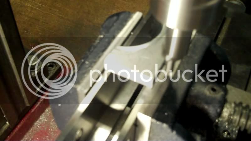
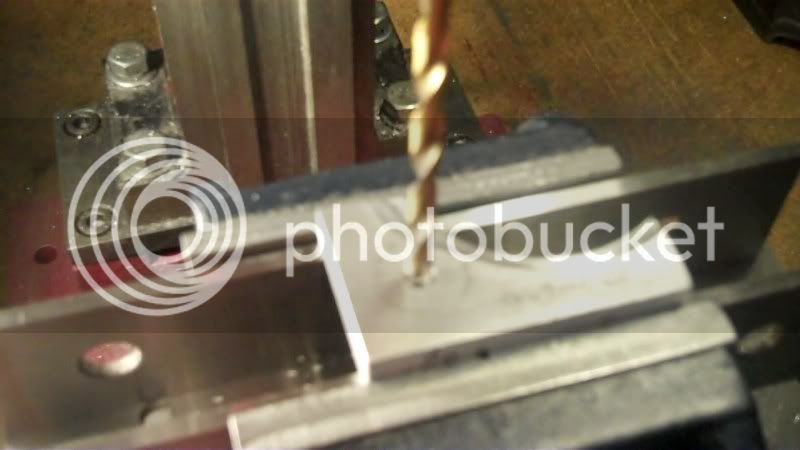
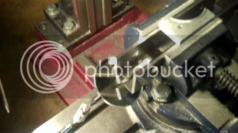
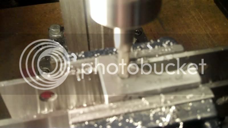
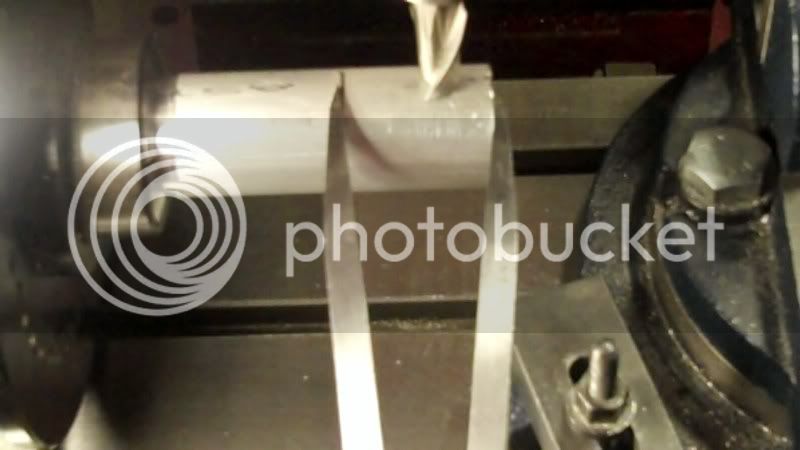
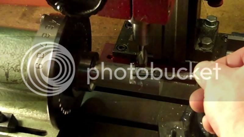
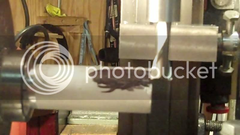
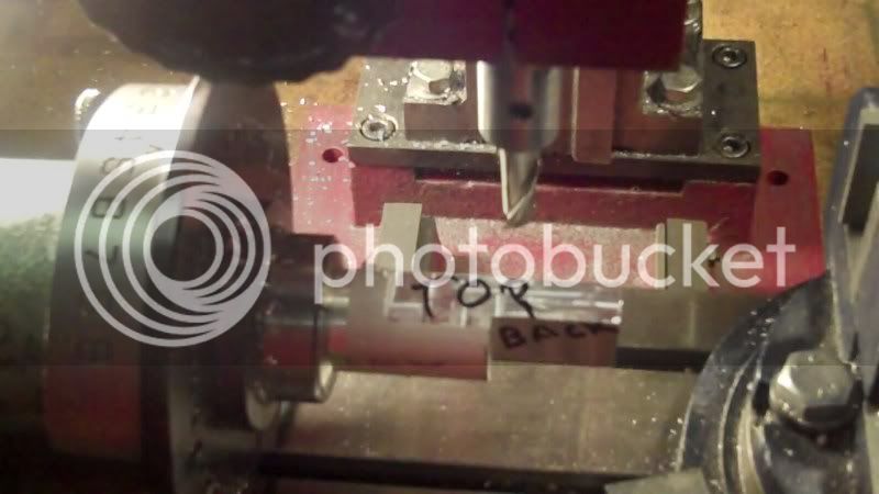
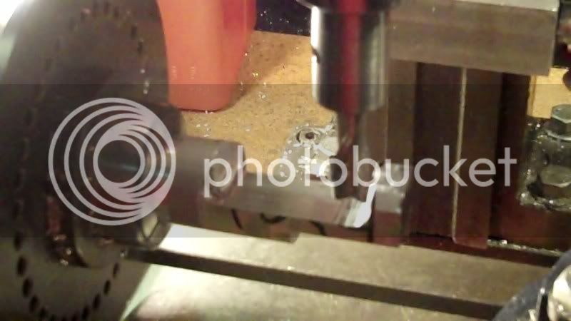
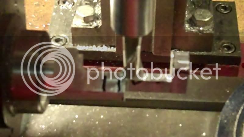
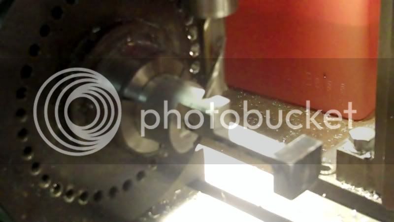
Here i'm drilling start holes for the endmill to fit down inside.
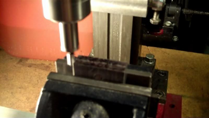
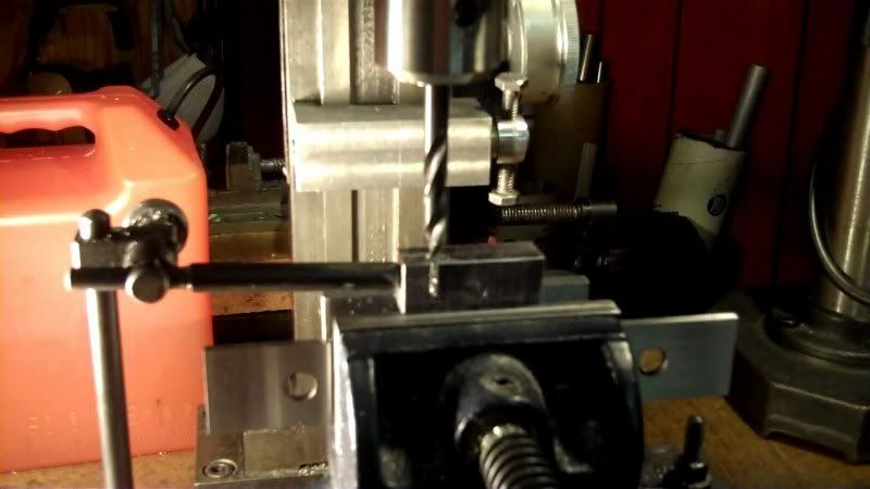
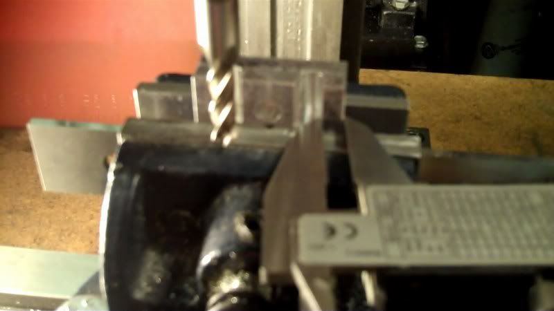
Now I bring the endmill down into the hole, to machine the slot forward, on the 'Y' axis.
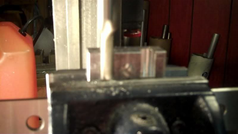
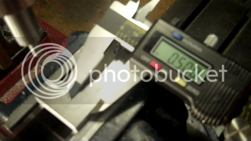
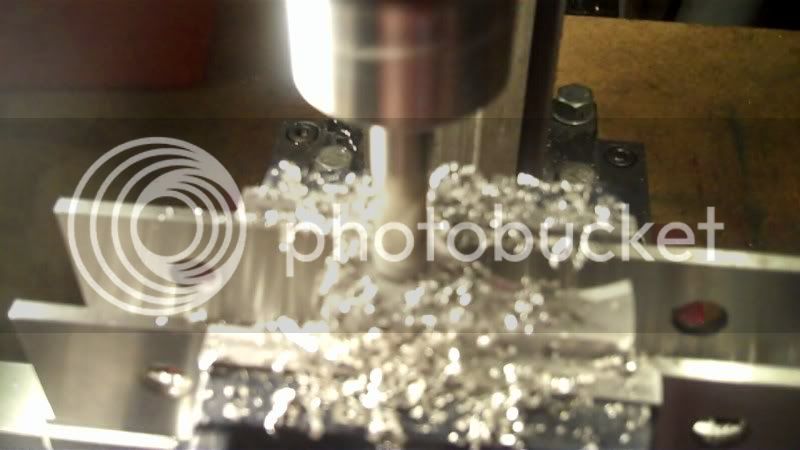
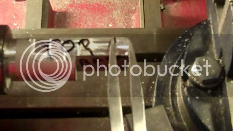
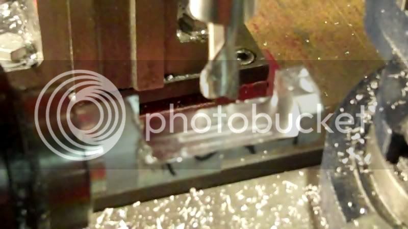
Now for the fine turning to bring evrything better to size in relation to both sides.
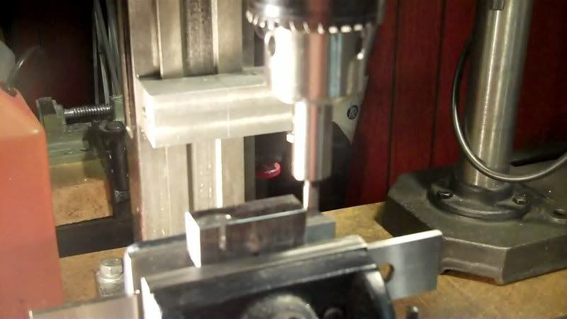
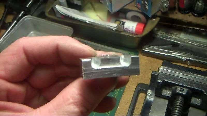
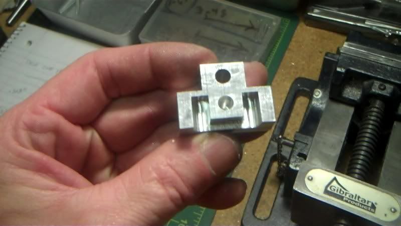
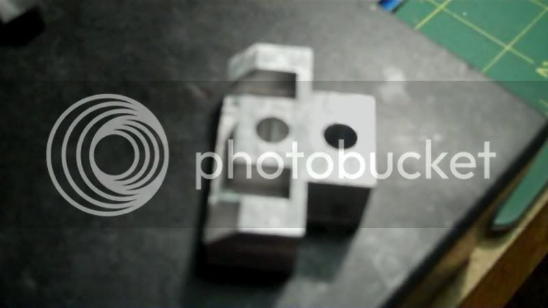
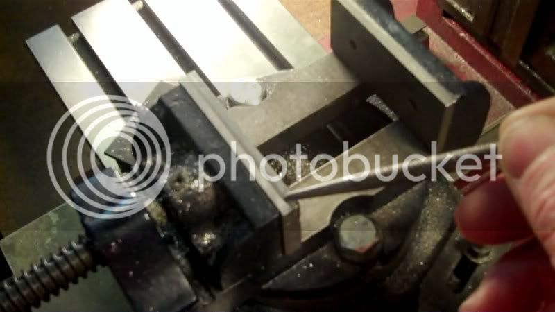
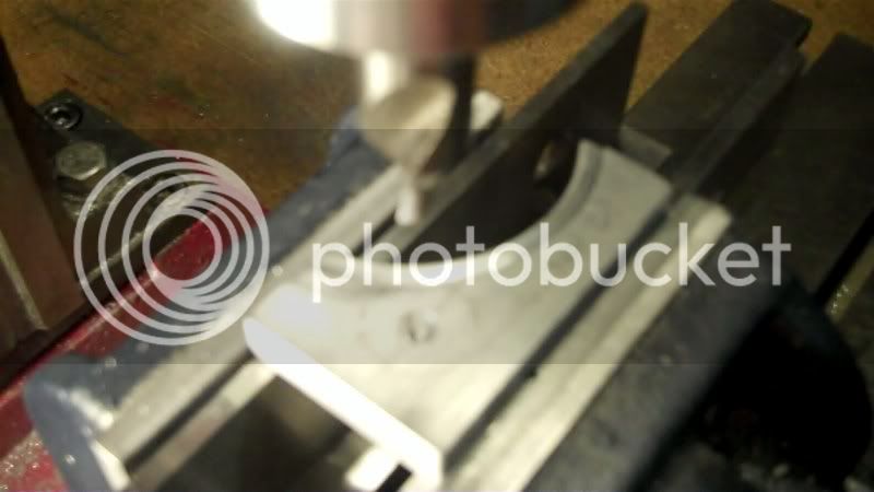
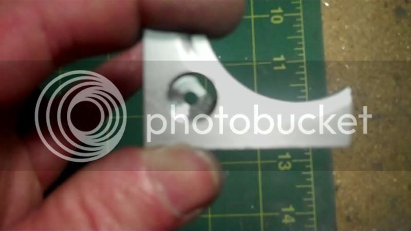
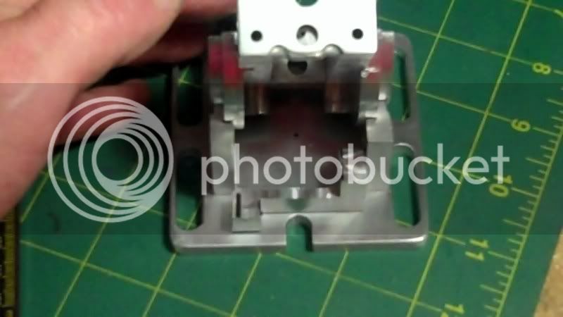
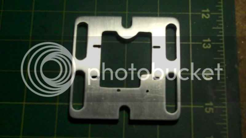
Now the top of the tapped hole needs to have the top portion machined down, to give the appearance of a Nut fixed to the jaw.
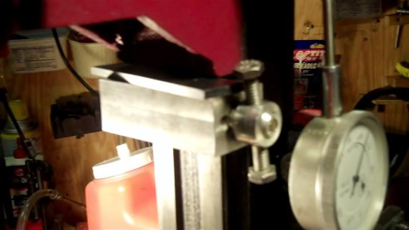
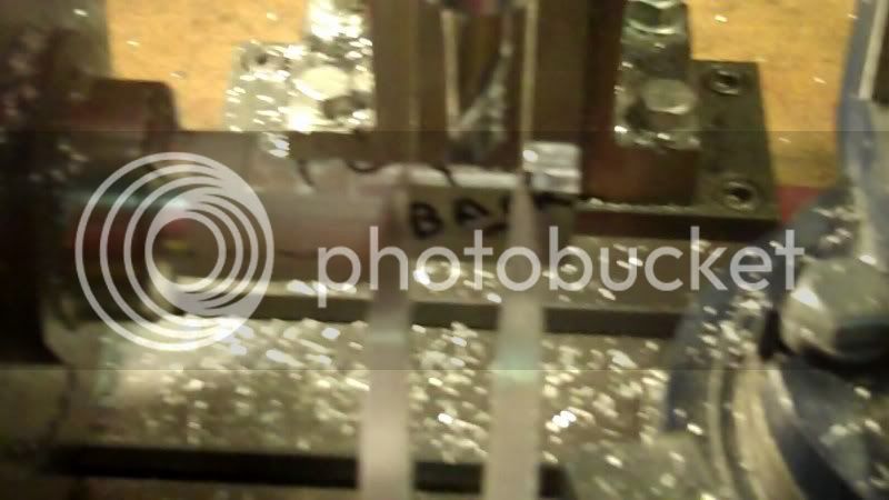
So some height adjustments
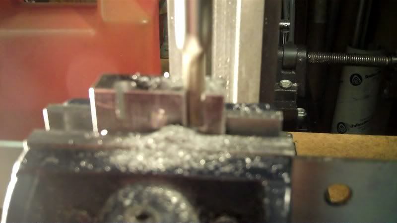
I used a parrallel on my depth stop to reset the stop for the depth of cut.
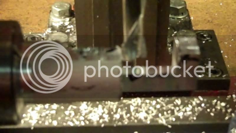
and the machining of the top portion,
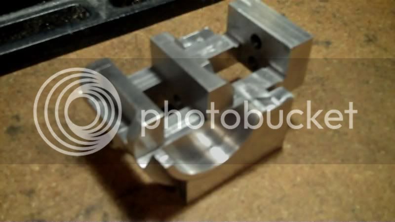
Now the endmill left a radius against the nut portion on the side edges,
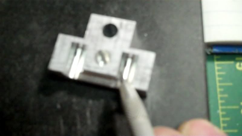
due to the way the slots were machined,
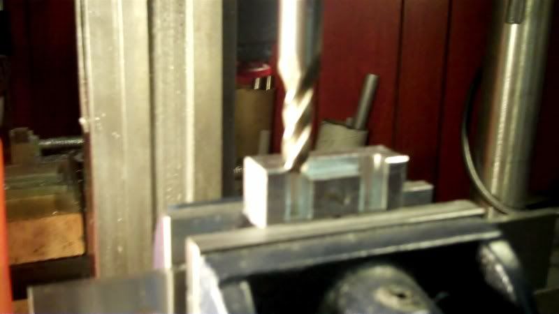
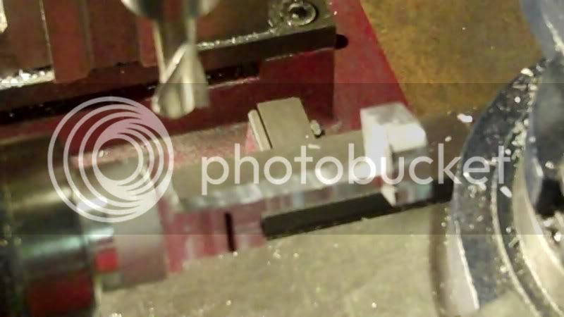
so using a smaller endmill, I repositioned the workpiece to be machined on the horizontal rather than the vertical as before.
lining it up to the slot
and setting the height,
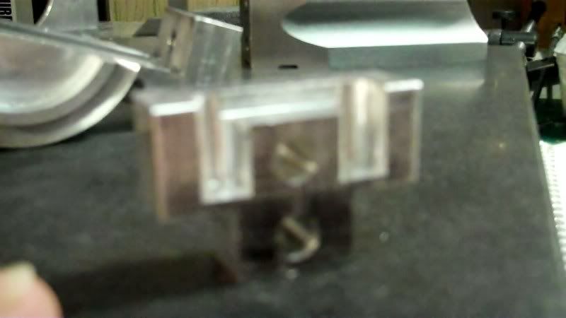
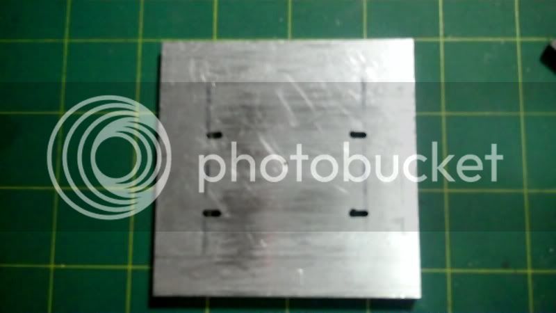
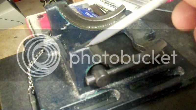
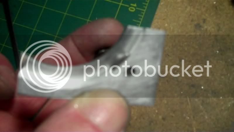
cleaning up the edges
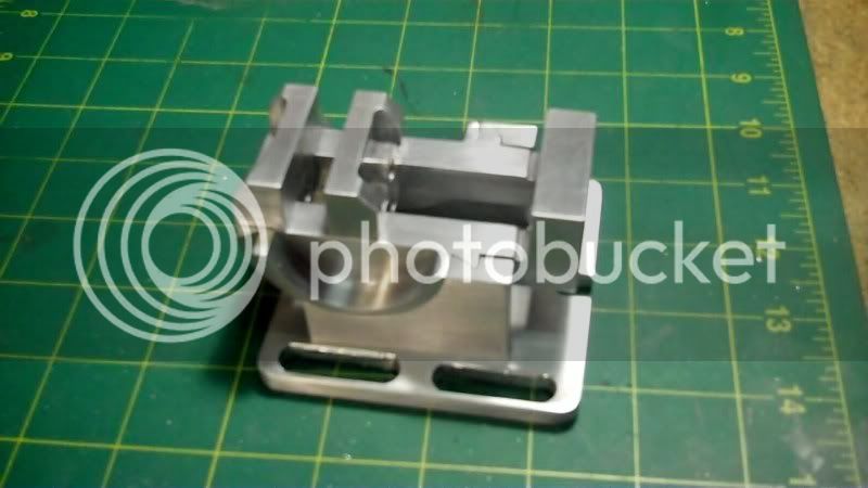
there see,,, that wasn't so bad!!
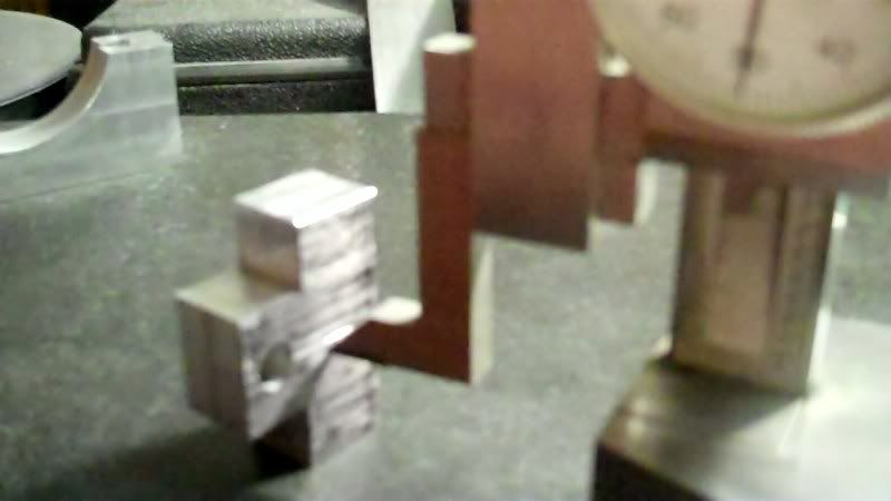
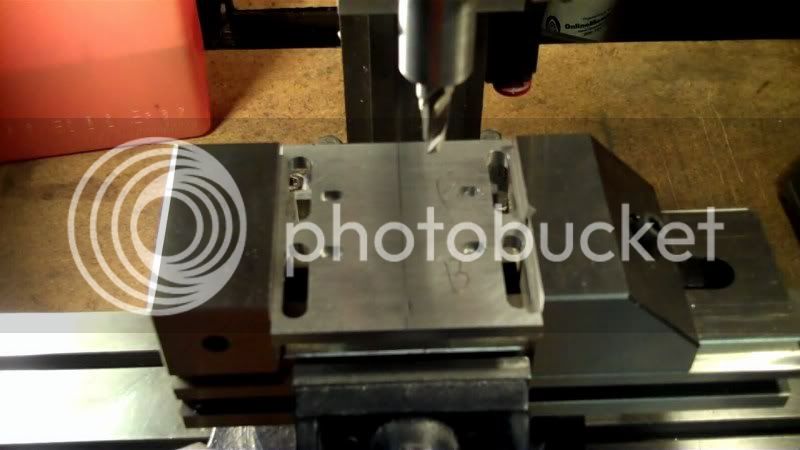
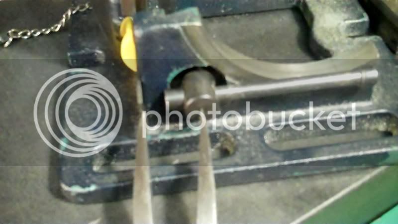
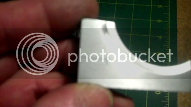
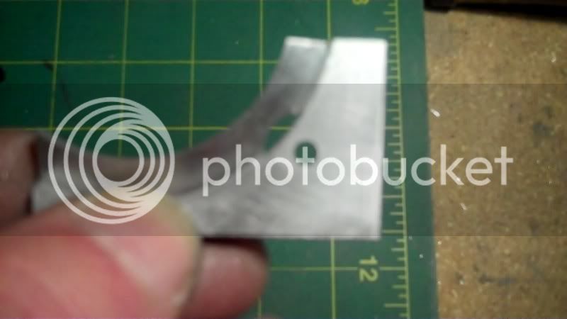
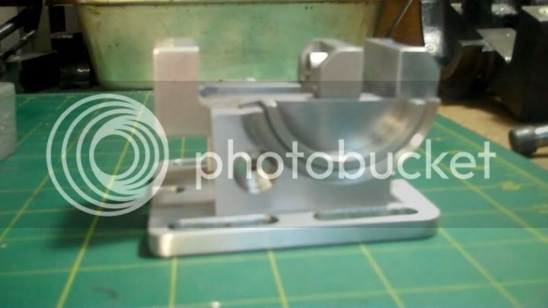
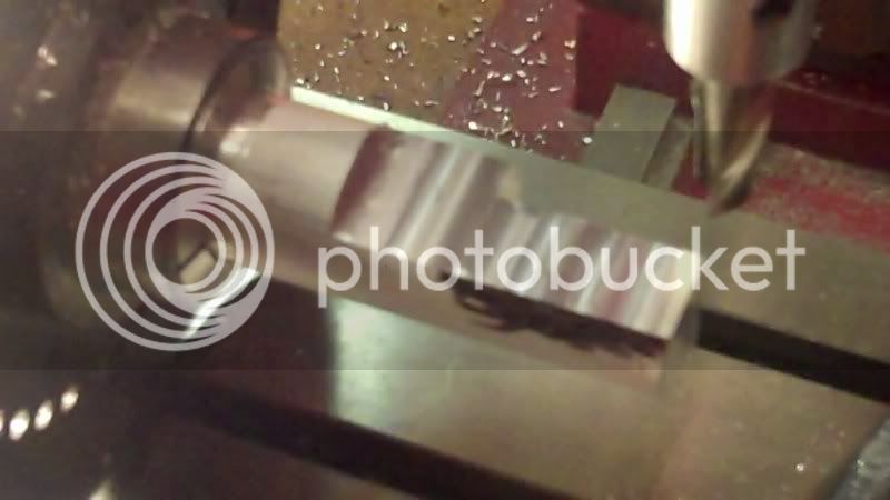
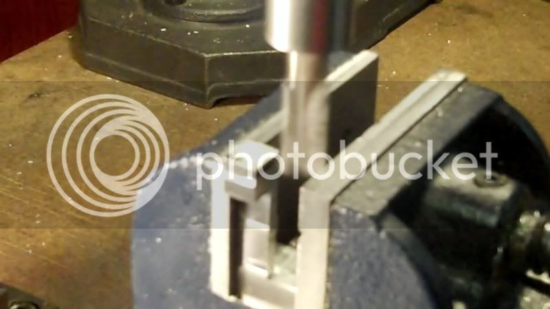
Now to cut the angles again, at the top of the jaw,

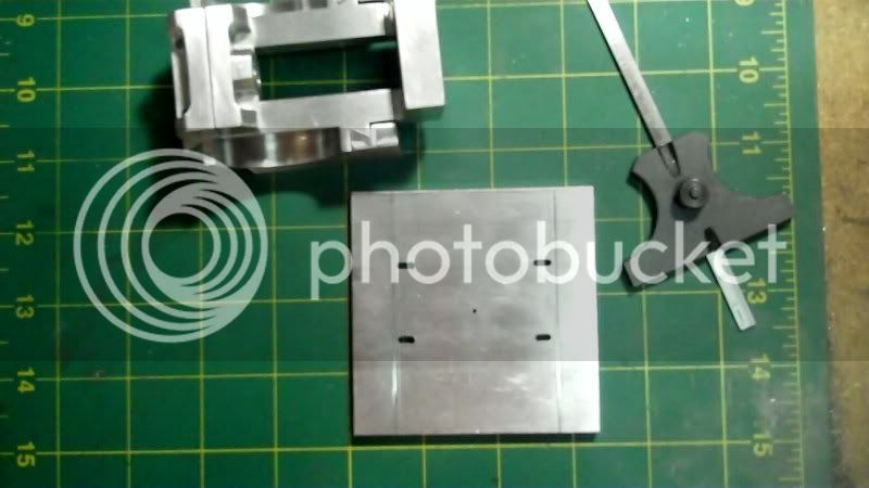
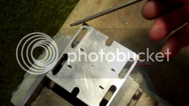
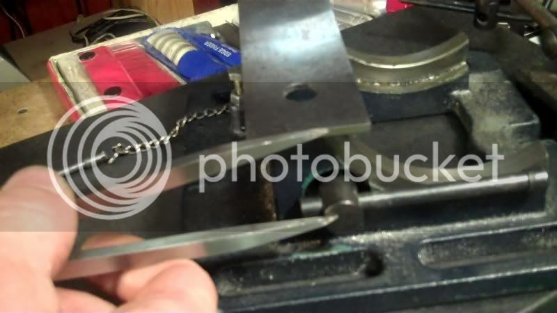
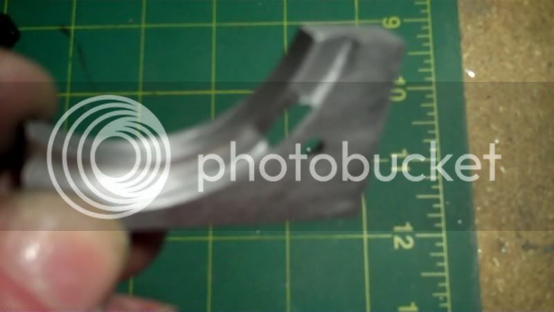
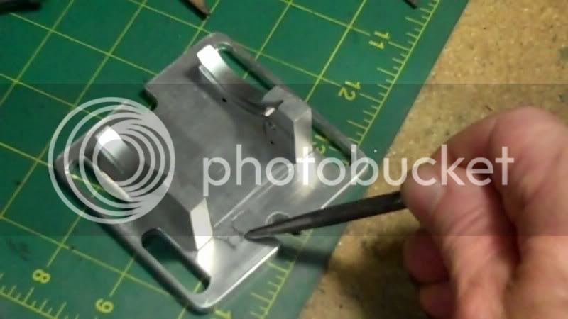
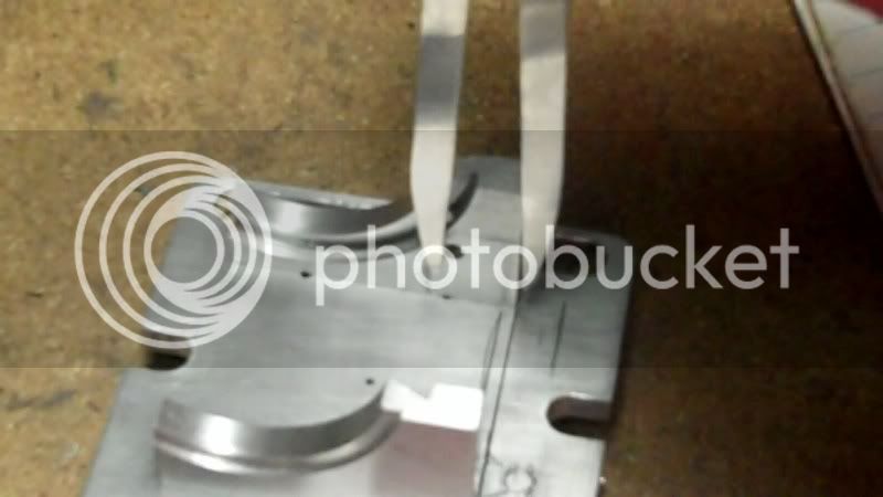
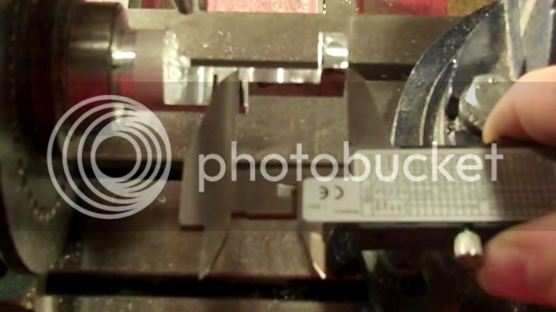
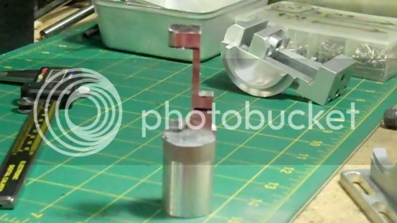
Now I made some marks to file down to to shape out the nut portion on this workpiece. (moveable jaw)
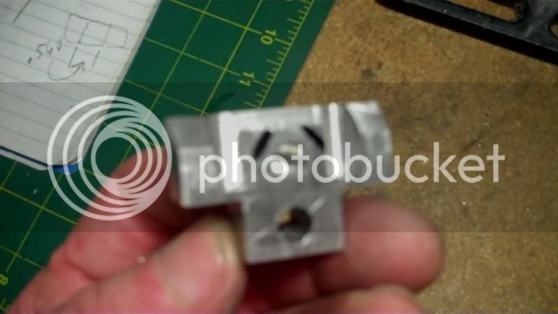
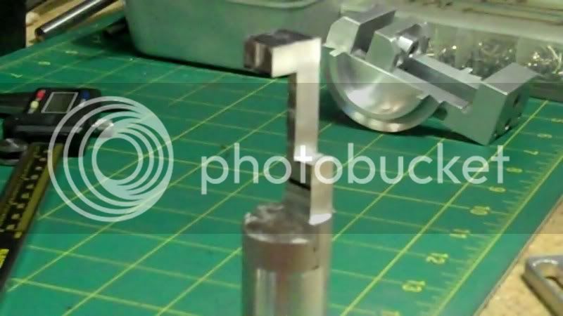
after some filing,
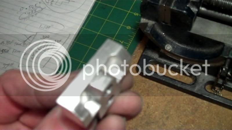
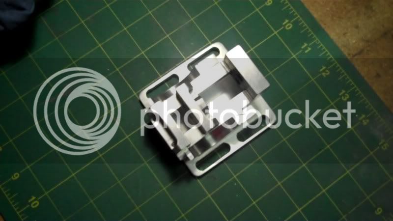
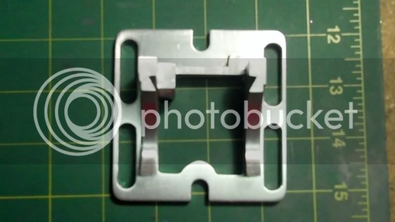
front angle of model
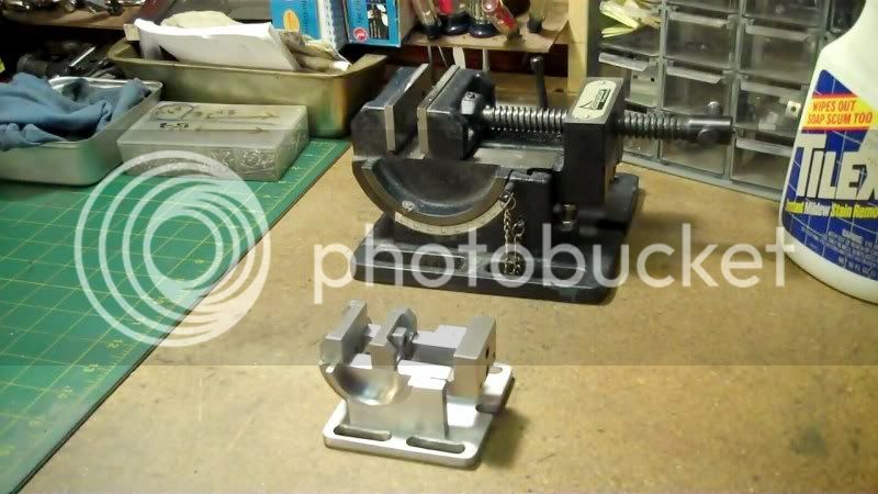
Next will be, either the base work, or some lathe work for the leadscrew and stabilizer bar.
Have fun in the shop..
Thankyou gentleman, for the kind compliments.
and for following along in this thread.
----------------------------------------------
This weeks progress, doing a little each evening, for the last couple days,
it was now time to start working on the moveable jaw, I layed everything out from center of the workpiece,
and now I needed away to keep everything lined up, so I used my reamer, which was used to ream these holes, as the lineup bar.
then I clamped the moveable jaw next to the fixed jaw to line up and transfer a centerpoint, for the nut portion on this jaw, to be drilled at.
drilling and tappping, for this nut portion,
again to keep visual perspective on the workpiece, I did all machining from edge references, rather than center. As I did before, this ensures that features will be very close to mirror images from one side to the other. I could do it all from centerlines, tot, but this seems to be better choice at this point.
Here i'm drilling start holes for the endmill to fit down inside.
Now I bring the endmill down into the hole, to machine the slot forward, on the 'Y' axis.
Now for the fine turning to bring evrything better to size in relation to both sides.
Now the top of the tapped hole needs to have the top portion machined down, to give the appearance of a Nut fixed to the jaw.
So some height adjustments
I used a parrallel on my depth stop to reset the stop for the depth of cut.
and the machining of the top portion,
Now the endmill left a radius against the nut portion on the side edges,
due to the way the slots were machined,
so using a smaller endmill, I repositioned the workpiece to be machined on the horizontal rather than the vertical as before.
lining it up to the slot
and setting the height,
cleaning up the edges
there see,,, that wasn't so bad!!
Now to cut the angles again, at the top of the jaw,
Now I made some marks to file down to to shape out the nut portion on this workpiece. (moveable jaw)
after some filing,
front angle of model
Next will be, either the base work, or some lathe work for the leadscrew and stabilizer bar.
Have fun in the shop..
- Joined
- Nov 12, 2009
- Messages
- 1,427
- Reaction score
- 221
Fantastic build mate!!
but your pics need work :big:
I don't know if your digital is the same as mine. but if u hold the button half way it may auto focus.
I also use the flower mode ( micro or something i think its called )
great work .
Pete
but your pics need work :big:
I don't know if your digital is the same as mine. but if u hold the button half way it may auto focus.
I also use the flower mode ( micro or something i think its called )
great work .
Pete
Very nice, well documented project.----and I think Pete means "macro".----Brian
- Joined
- Dec 5, 2009
- Messages
- 510
- Reaction score
- 47
Pete, Brian, thankyou for the compliments.
I used to use my digital camera, with the autofocus, but it kept on eating up battery power, and I would take the batteries out, and the battery cover is now cracking, so I am now using my "FLIP" (tm), video camera, and using the software that comes with it, to capture snapshots, during a video replay, so I may have some movement going on that the snapshot is taking, that makes it look a little out of focus.
---------------------------
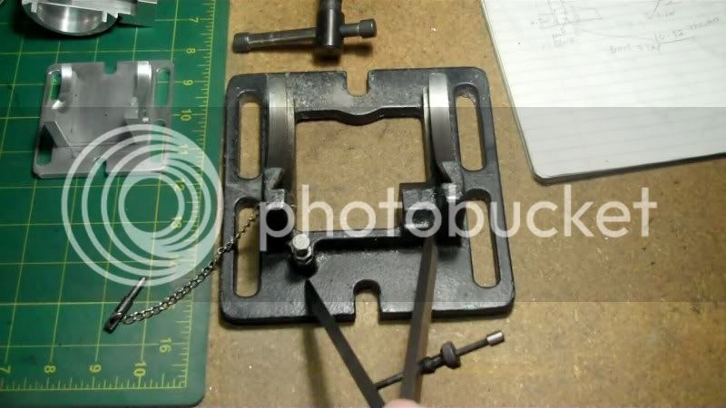
I need to correct myself on the last post, where I said about tapping the nut portion on the moveable jaw. That is wrong, That is a drilled and reamed blind hole, to contain the end of the leadscrew. The only tapping has already been done on the vice body in the back to drive the lead screw.
Todays progress
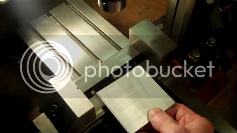
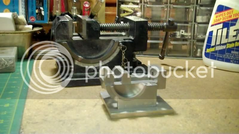
Time to make the base assembly to assemble temporarily the dovetail slides to check for running fit.
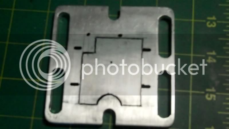
The blank all milled to proper dimensions.
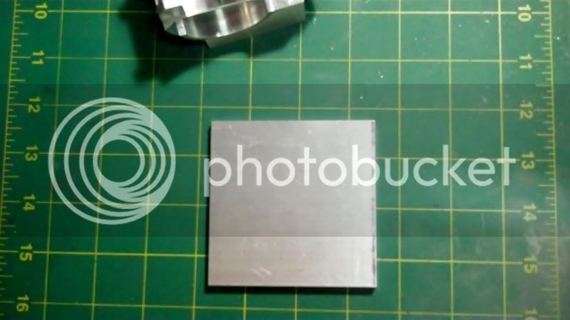
The blank is to big for my vice, by a 1/4"
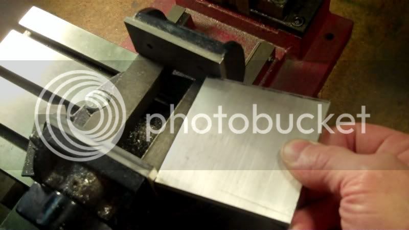
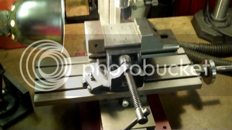
I could take the back soft jaw off and it would fit,
or I could use my bigger vice, it is a screwless kind,
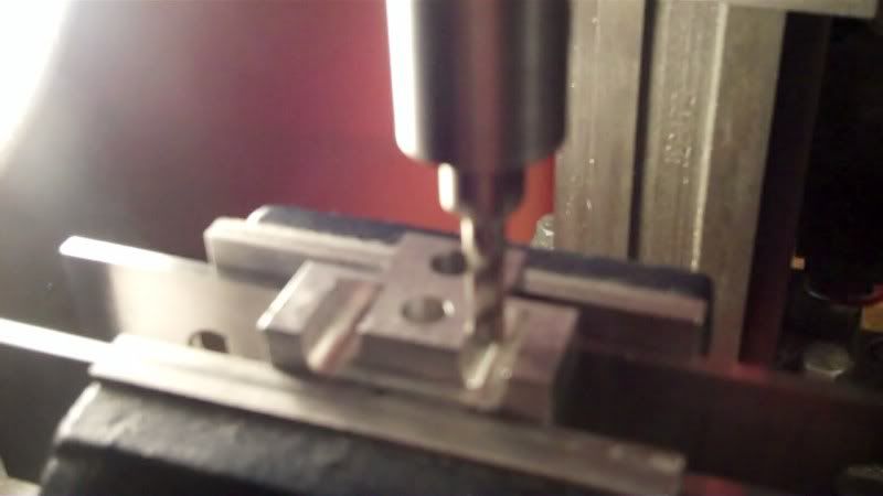
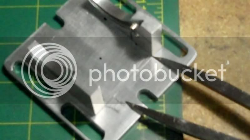
Now all the edge locating
to find the center of the workpiece. and drill a reference hole,
now secure the written down dimensions

and start drilling 3/32" holes for 2-56 screws, for the assembly screw holes to mount the top portion to the base.
I decided to give a quick check,

and I'm glad I did, because my math was off about a 1/4"
first I checked actual dimensions on the drawing
then transfered that to the drilled workpiece, to see how much error was made

drew the lines to show how far the holes needed to be over too
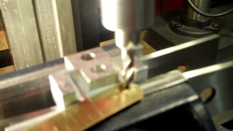
So to fix it, I used a 3/32" carbide circuit board bit to rout out a slot at each hole location
Now back on track, it was time to drill and tap for 2-56 screws into the bottoms of each dovetail slide piece. First I used a parrallel bar to line the flat bottom portion, of the workpiece up with the vice, to make everything parrallel to the table,
then located , to drill and tap.
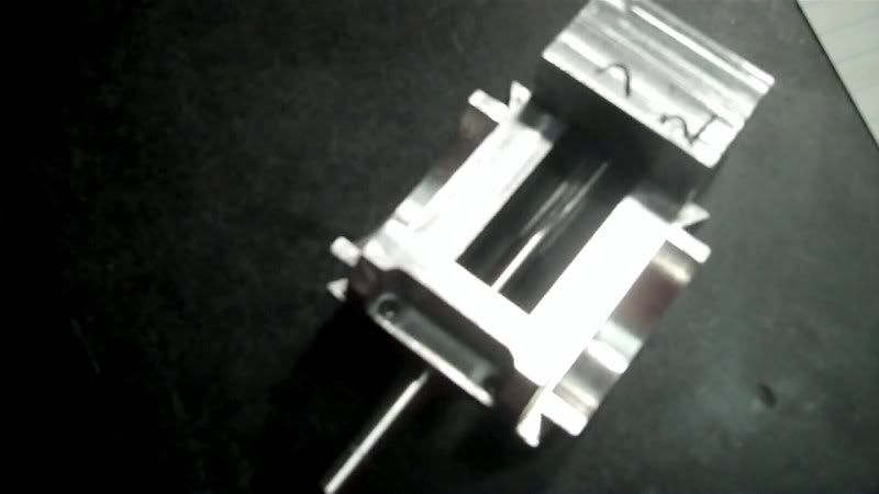
anf to check for a sliding fit of the mechanical dovetail slide. Make sure everything lines up after the slots had to be milled out.
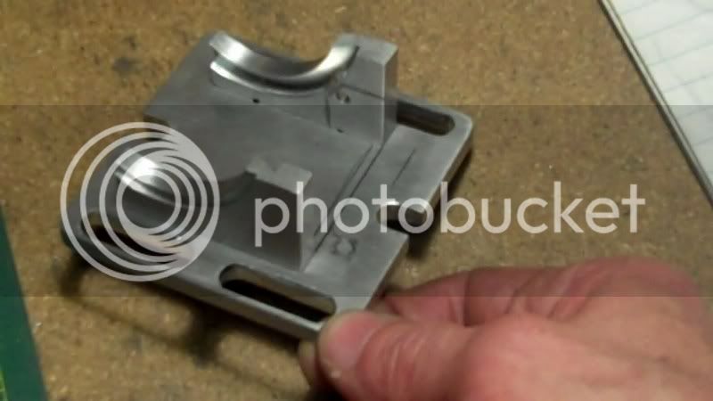
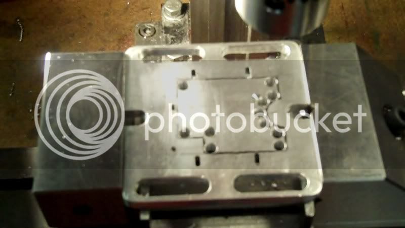
Now itts time to do all the slot featurees on the base.
This time when I put the workpiece in my bigger vice, I put the bigger vice into the smaller vice, so I didn't have to take my original small vice back off again. (The kind of setup toolmakers use, with those small toolmakers vices.)
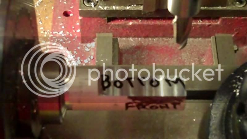
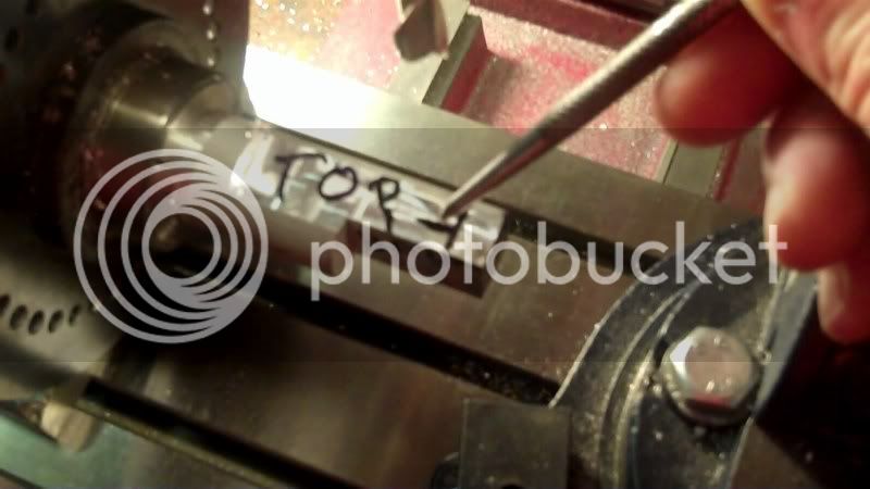
Now since I am starting to put final sanding finishes on these workpieces, I won't scratch any more layout marks, I'll use a soft lead pencil, to locate the center, and any other layout markings.
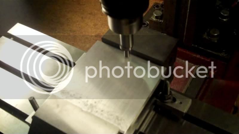
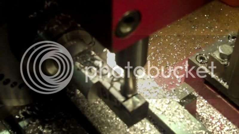
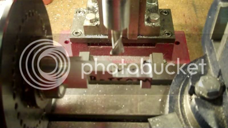
Now I can drill all the start and stop holes for my mill cutter can than work into.
and the milling at these holes, for slot features on the base of the workpiece.
Now some corner rounding filing
and what is done so far,
Next I'll start setting up to mill a recess on the one dovetailed upright to incorporate a angle guage sticker, and some milling ontop to place a logo sticker of the vice, and drill for pin locations into the dovetail section, as well as a locking pin on the other dovetail section, and a depth stop, ect..
still a little bit more to do, yet,,,
Thanks for looking in,
have a great day...
I used to use my digital camera, with the autofocus, but it kept on eating up battery power, and I would take the batteries out, and the battery cover is now cracking, so I am now using my "FLIP" (tm), video camera, and using the software that comes with it, to capture snapshots, during a video replay, so I may have some movement going on that the snapshot is taking, that makes it look a little out of focus.
---------------------------
I need to correct myself on the last post, where I said about tapping the nut portion on the moveable jaw. That is wrong, That is a drilled and reamed blind hole, to contain the end of the leadscrew. The only tapping has already been done on the vice body in the back to drive the lead screw.
Todays progress
Time to make the base assembly to assemble temporarily the dovetail slides to check for running fit.
The blank all milled to proper dimensions.
The blank is to big for my vice, by a 1/4"
I could take the back soft jaw off and it would fit,
or I could use my bigger vice, it is a screwless kind,
Now all the edge locating
to find the center of the workpiece. and drill a reference hole,
now secure the written down dimensions
and start drilling 3/32" holes for 2-56 screws, for the assembly screw holes to mount the top portion to the base.
I decided to give a quick check,
and I'm glad I did, because my math was off about a 1/4"
first I checked actual dimensions on the drawing
then transfered that to the drilled workpiece, to see how much error was made
drew the lines to show how far the holes needed to be over too
So to fix it, I used a 3/32" carbide circuit board bit to rout out a slot at each hole location
Now back on track, it was time to drill and tap for 2-56 screws into the bottoms of each dovetail slide piece. First I used a parrallel bar to line the flat bottom portion, of the workpiece up with the vice, to make everything parrallel to the table,
then located , to drill and tap.
anf to check for a sliding fit of the mechanical dovetail slide. Make sure everything lines up after the slots had to be milled out.
Now itts time to do all the slot featurees on the base.
This time when I put the workpiece in my bigger vice, I put the bigger vice into the smaller vice, so I didn't have to take my original small vice back off again. (The kind of setup toolmakers use, with those small toolmakers vices.)
Now since I am starting to put final sanding finishes on these workpieces, I won't scratch any more layout marks, I'll use a soft lead pencil, to locate the center, and any other layout markings.
Now I can drill all the start and stop holes for my mill cutter can than work into.
and the milling at these holes, for slot features on the base of the workpiece.
Now some corner rounding filing
and what is done so far,
Next I'll start setting up to mill a recess on the one dovetailed upright to incorporate a angle guage sticker, and some milling ontop to place a logo sticker of the vice, and drill for pin locations into the dovetail section, as well as a locking pin on the other dovetail section, and a depth stop, ect..
still a little bit more to do, yet,,,
Thanks for looking in,
have a great day...
zeeprogrammer
Well-Known Member
- Joined
- Mar 14, 2009
- Messages
- 3,362
- Reaction score
- 13
I just finished reading this thread through. Very enjoyable...I can't get enough of these kinds of projects. I appreciate the detail too.
Just a side note...re the digital camera. You should be able to get a power cord for it. It's not that expensive and pays for itself (against batteries) quickly. But you do have to be careful with the cord...it's a trip hazard.
Just a side note...re the digital camera. You should be able to get a power cord for it. It's not that expensive and pays for itself (against batteries) quickly. But you do have to be careful with the cord...it's a trip hazard.
- Joined
- Dec 5, 2009
- Messages
- 510
- Reaction score
- 47
Carl, (zeep)
Thanks, for looking in.
Also thankyou for the suggestion of getting an AC adaptor, for my camera, I have one ordered, from the amazon.com. Along with another workshop series book, "spindles"
---------------------------------------------------
Ok the progress on this model, is in the area of patience and clear thinking thru on setups.
I want to see if I can duplicate as much as possible the mechanical, and asthetic functions, from the original vise, in this model.
I am now looking over the original vise, and seeing what parts I can do on the model and what I can't do, to keep it close to fidelity, with the original.
These are the areas I would have skipped over, when I first got into this hobby, but now that I have seen the great details that you guys do on your models, I have the inspiration to forge ahead in trying to perfect my abilities in this hobby as well.
So this is the start of the fine details to work on next., To take this from a abstract build, to a close to accurate build of a scale model.
With that all said, here is the details I'm processing now.
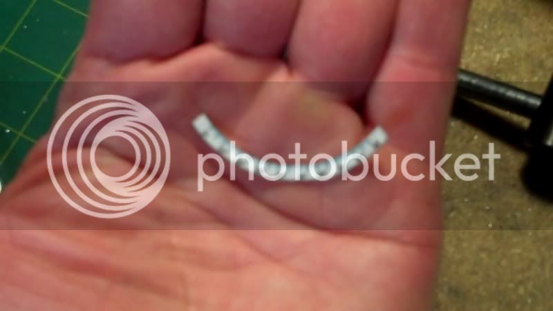
On this side of the original vise is a 1/8" deep recess,
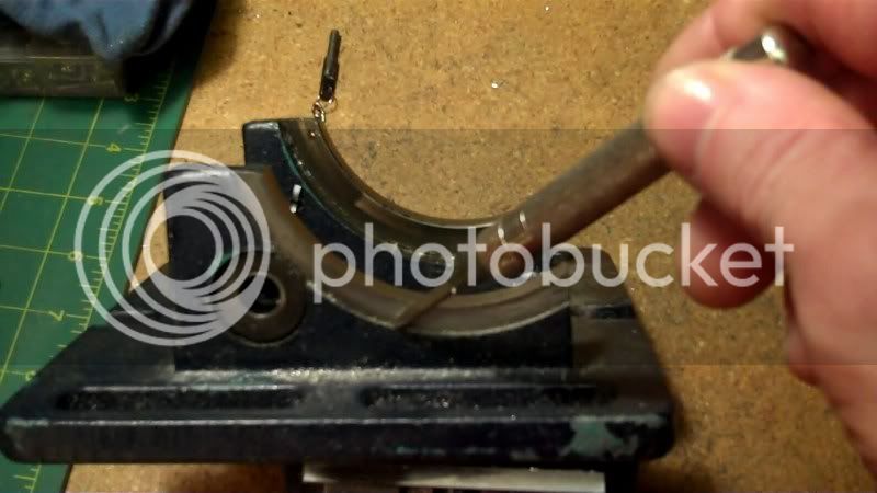
and on the other side is another recess, with a angle guage printed on it.
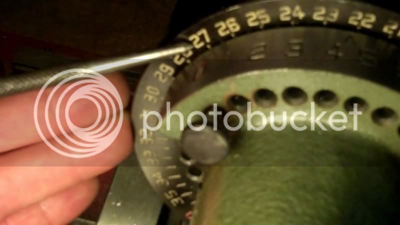
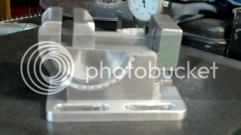
So I need to setup my rotary table to make this cuttings, first I need to once again secure the radius dimensions,

indicate in my RT.
Now, comes some thinking thru, this setup, since I no longer have the original radius hole in the workpieces, I have no way of setting the distance for the radius turning on these pieces.
Several ideas come to mind, such as make a jig to hold the workpieces the required distance away from the RT center, along those lines,
OR, just set the rotary table the offset distance required, on the 'Y' axis, as I would normally do if I had a radius reference hole present,
Thennnnn.... do this.....


The spindle was not running, I just set the spindle on the 'Z' axis low enough to make good pencil point contact, then rotated the RT, to make the reference circle.
I know your wondering how acurate that would be, with the drill chuck holding a pencil, well it's not accurate at all, the pencil wobbles quite a bit,
Thats why before I did all that above, I did this FIRST,,,,,,,

even though the pencil body swirved around, the point stayed right on center like a wiggler does.
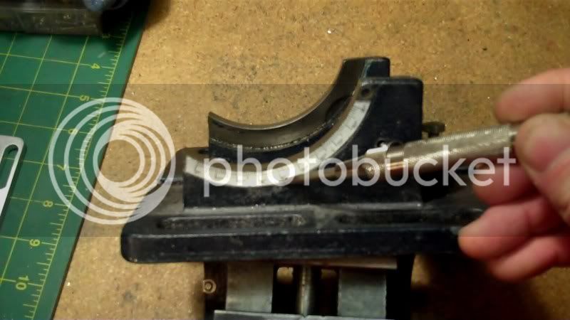
Time to test fit the workpiece to see if I got a accurate reference circle to line up too.

looks good so far, ok now I'll use some double stick tape
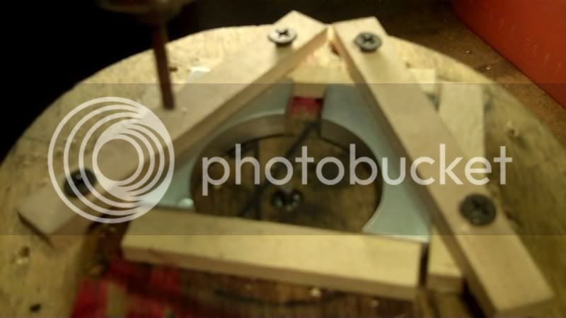
and paste them down onto the wood faceplate, to align them up for later clamping.

hotmelt glue on some backer wood strips to keep everything in alignment
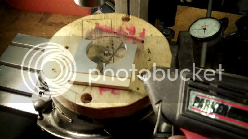
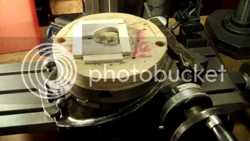
and now the machining of these pieces.

Thanks for looking in....
Thanks, for looking in.
Also thankyou for the suggestion of getting an AC adaptor, for my camera, I have one ordered, from the amazon.com. Along with another workshop series book, "spindles"
---------------------------------------------------
Ok the progress on this model, is in the area of patience and clear thinking thru on setups.
I want to see if I can duplicate as much as possible the mechanical, and asthetic functions, from the original vise, in this model.
I am now looking over the original vise, and seeing what parts I can do on the model and what I can't do, to keep it close to fidelity, with the original.
These are the areas I would have skipped over, when I first got into this hobby, but now that I have seen the great details that you guys do on your models, I have the inspiration to forge ahead in trying to perfect my abilities in this hobby as well.
So this is the start of the fine details to work on next., To take this from a abstract build, to a close to accurate build of a scale model.
With that all said, here is the details I'm processing now.
On this side of the original vise is a 1/8" deep recess,
and on the other side is another recess, with a angle guage printed on it.
So I need to setup my rotary table to make this cuttings, first I need to once again secure the radius dimensions,
indicate in my RT.
Now, comes some thinking thru, this setup, since I no longer have the original radius hole in the workpieces, I have no way of setting the distance for the radius turning on these pieces.
Several ideas come to mind, such as make a jig to hold the workpieces the required distance away from the RT center, along those lines,
OR, just set the rotary table the offset distance required, on the 'Y' axis, as I would normally do if I had a radius reference hole present,
Thennnnn.... do this.....
The spindle was not running, I just set the spindle on the 'Z' axis low enough to make good pencil point contact, then rotated the RT, to make the reference circle.
I know your wondering how acurate that would be, with the drill chuck holding a pencil, well it's not accurate at all, the pencil wobbles quite a bit,
Thats why before I did all that above, I did this FIRST,,,,,,,
even though the pencil body swirved around, the point stayed right on center like a wiggler does.
Time to test fit the workpiece to see if I got a accurate reference circle to line up too.
looks good so far, ok now I'll use some double stick tape
and paste them down onto the wood faceplate, to align them up for later clamping.
hotmelt glue on some backer wood strips to keep everything in alignment
and now the machining of these pieces.
Thanks for looking in....
- Joined
- Dec 5, 2009
- Messages
- 510
- Reaction score
- 47
Steamer (Dave), and Chazz,
Thankyou Gentleman, for the kind compliments.
It is much appreciated.
------------------------------------------------
This evening has been, one of careful thinking and laying out of areas for machining on the workpiece.
I am working on making the clamping system
it utilizes three components
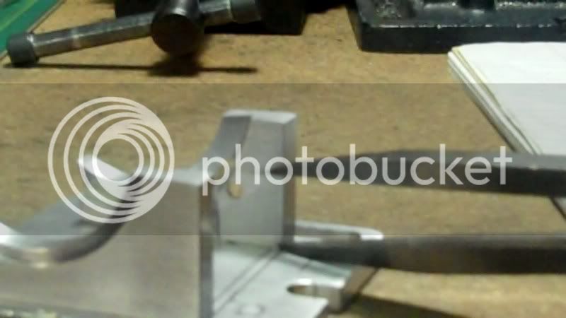
a clamping screw, and a gib washer, (more on that in a moment) and a block with a tapped hole to recieve the clamping screw, situated on the interior of the vice floor.
the gib washer is a washer that has a dovetail feature cut into it at the top
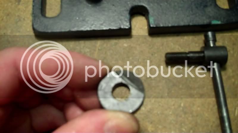
it is located in the hole bored into the vice dovetailed bottom slide
then the clamping screw bolts onto the inside block.
The system is set up so that the dovetailed slide has a hole cut part way through it
to allow the dovetailed washer
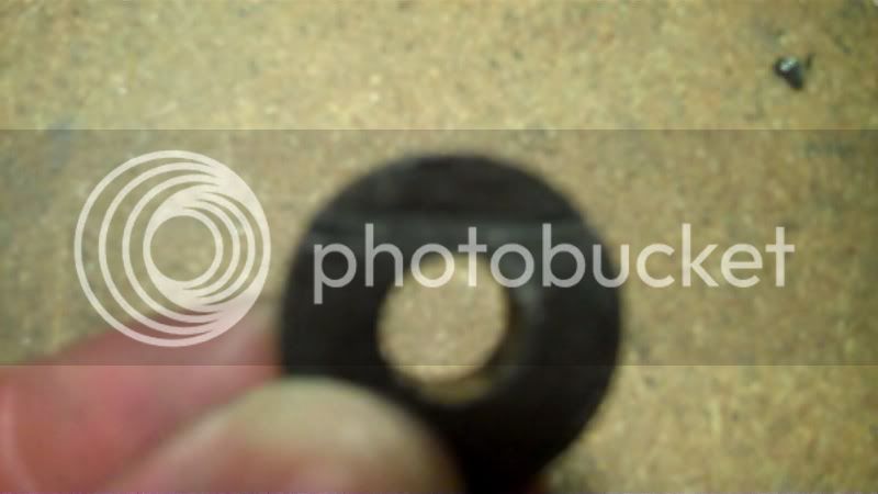
to bear against the top dovetail portion of the vice, so when the clamp screw is tightened, it forces the washer to cinch the top of the vice dovetail portion, thereby clamping it in position.
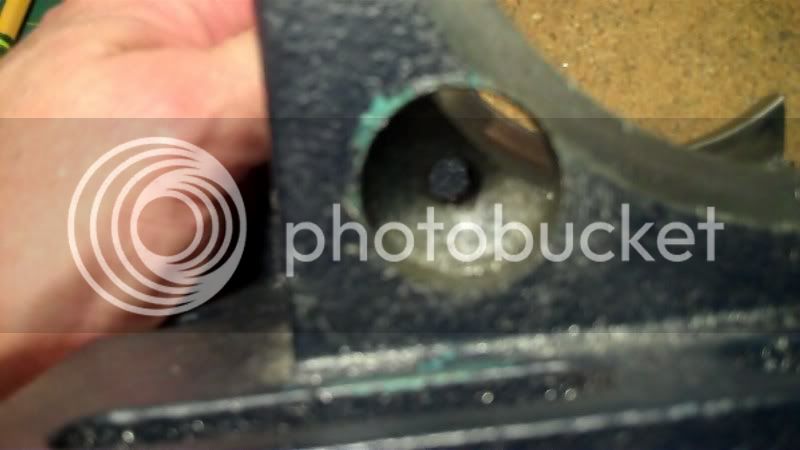
Now further investigation of this shows that the hole bored into the vice, does not go all the way through, but allows a small portion of the dovetail slide to stay intact

this is so that the top dovetail slide will have a continuous bearing surface to ride smoothly on, as well as keeping the strength of this intact as well.
Now this leftover portion is raised a bit

above the nut housing block

here you can see the continuation of the dovetail slide with the hole bore partly trough it.
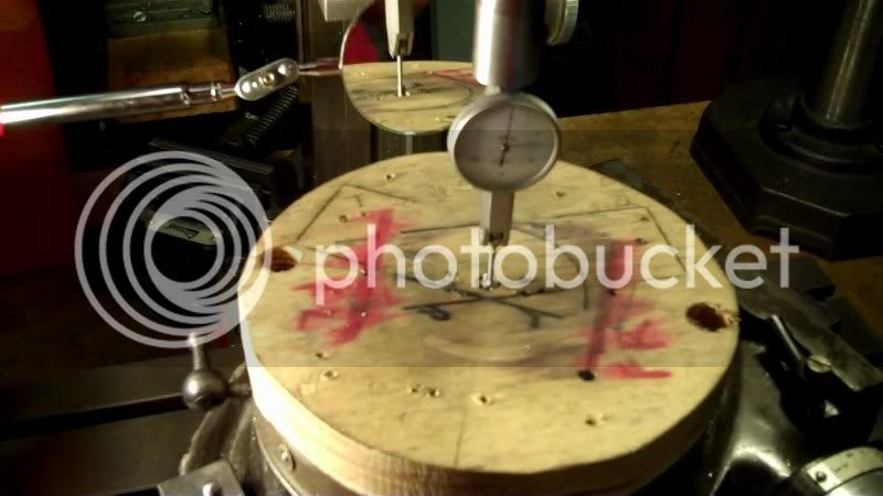
OK, the best way for me to duplicate this marvelous mechanical design of a clamping system, is to choose reference points to work from.
The most obvious and best choice would be to reference everything from the center of the bore
I'll use the left edge
and the top
to locate the bore on the workpiece
clamping a straight edge to the back side I can get dimensions needed
and setting a parrallel on top to get these dimensions needed.
transfer these dimensions to the workpiece
then checking for hole alignment I used a compass to draw a 1/2' circle to represent the final bore size for my model
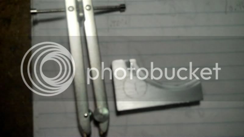
the original bore size is 1" so to keep to scale I using 1/2"
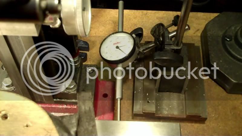
Now to make sure I know when to stop the bore so as to keep the leftover material intact, I need one last measurement of the thickness of the workpiece.
Now even though I used the top edge of the original vise to get the dimensions to locate the bore,
I will now use the bottom of the workpiece to do all edge finding
and secure dimensions
to do all the machining.
The reason for this is because when I layout the nut block to get it in the right position, so the holes line up with the center of this bore, I will need to use the bottom of the block to reference off of, the top has no bearing on this matter seeing it is sticking up in the air and not grounded to anything with the piece it mates to.
But the bottom of both workpieces have a common ground.
machining operation begins
Now if I can I like to make a locating hole as soon as possible before any major work is done
since I'll be tapping with a 10-32 thread I can use a #21 bit to satisfy the locator hole.
Now I better check and make sure this hole did NOT get into the dovetail portion,, how acurate was my layout, well I can only tell by using a mirror to get underneath all this stuff to take a look
UH OH, OH NO, that hole is pretty close to the dovetail, AHH, did I mess up that much,
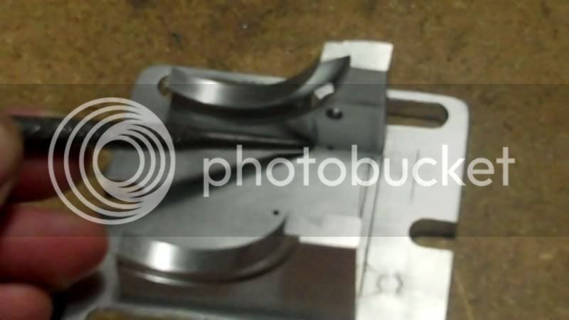
lets see how the original looks
WHEWWW, the original has its clearance hole close to its dovetail too, OK, then looks like it is close to scale at this point, so it should be ok then.
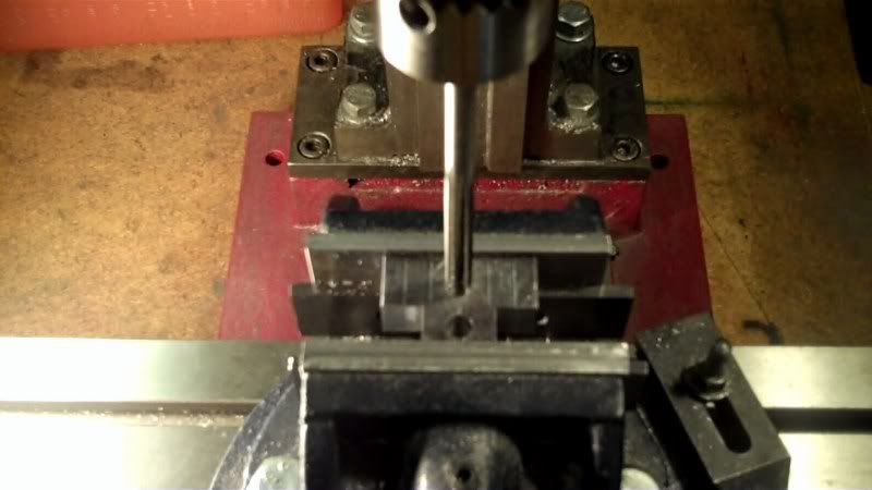
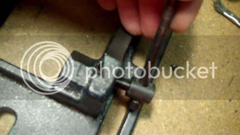
OK now I can set the depth of cut
Nope can't use these largish dia. drill bits, I wanted to use a 31/64 drill bit drill to specific depth, then ream to 1/2" diameter, buuuuttt, the depth I'm going is only around 1/4" and the large dia. bits have there large flutes in that area, I need a round flat bottom hole,
OK, I'll use these
start out small, and work my way up to 1/2" dia.
Now that the depth stop is set, I'll need to lacate the 'Z' axis for each change of endmill.
and away we go...

glad that's done.
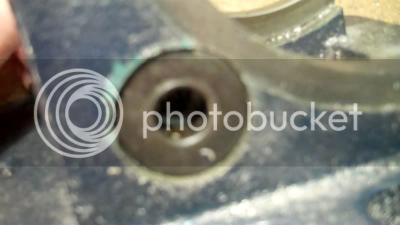
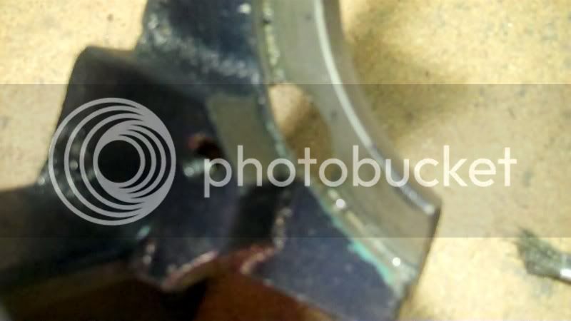
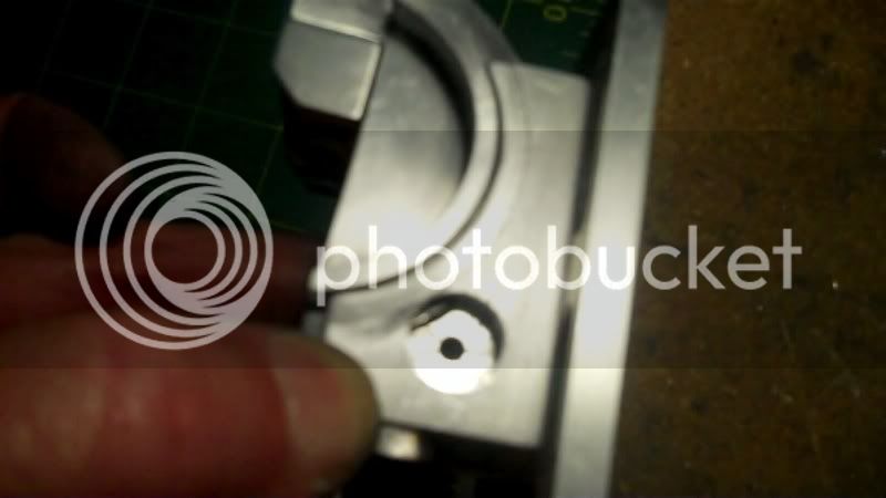
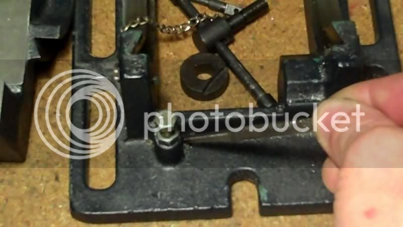
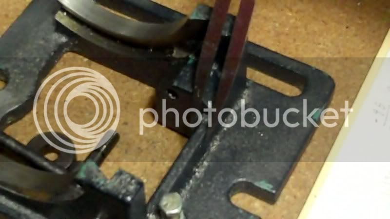
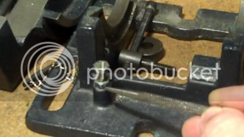
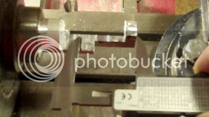
see the slot at the top to allow the dovetailed washer to bear against the slide.
Here, see if this shows it better.....
alright how about this way.....does it show more that way...
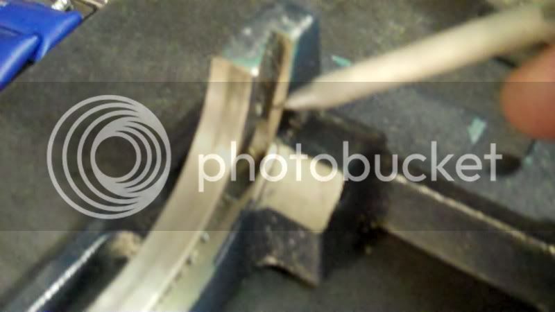
it is probably hard to tsee itl, but I'm sticking a 1/2" piece of rod into the bore, to check for it protruding through the interior dovetail..
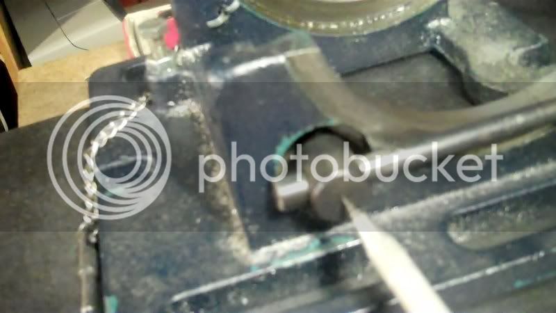
As the top portion is in position, you can see it's dovetailed slide through this clamping slot.
and this part is acomplished, Thank GOD...
Thanks for looking in,
Have fun in the shop..
Thankyou Gentleman, for the kind compliments.
It is much appreciated.
------------------------------------------------
This evening has been, one of careful thinking and laying out of areas for machining on the workpiece.
I am working on making the clamping system
it utilizes three components
a clamping screw, and a gib washer, (more on that in a moment) and a block with a tapped hole to recieve the clamping screw, situated on the interior of the vice floor.
the gib washer is a washer that has a dovetail feature cut into it at the top
it is located in the hole bored into the vice dovetailed bottom slide
then the clamping screw bolts onto the inside block.
The system is set up so that the dovetailed slide has a hole cut part way through it
to allow the dovetailed washer
to bear against the top dovetail portion of the vice, so when the clamp screw is tightened, it forces the washer to cinch the top of the vice dovetail portion, thereby clamping it in position.
Now further investigation of this shows that the hole bored into the vice, does not go all the way through, but allows a small portion of the dovetail slide to stay intact
this is so that the top dovetail slide will have a continuous bearing surface to ride smoothly on, as well as keeping the strength of this intact as well.
Now this leftover portion is raised a bit
above the nut housing block
here you can see the continuation of the dovetail slide with the hole bore partly trough it.
OK, the best way for me to duplicate this marvelous mechanical design of a clamping system, is to choose reference points to work from.
The most obvious and best choice would be to reference everything from the center of the bore
I'll use the left edge
and the top
to locate the bore on the workpiece
clamping a straight edge to the back side I can get dimensions needed
and setting a parrallel on top to get these dimensions needed.
transfer these dimensions to the workpiece
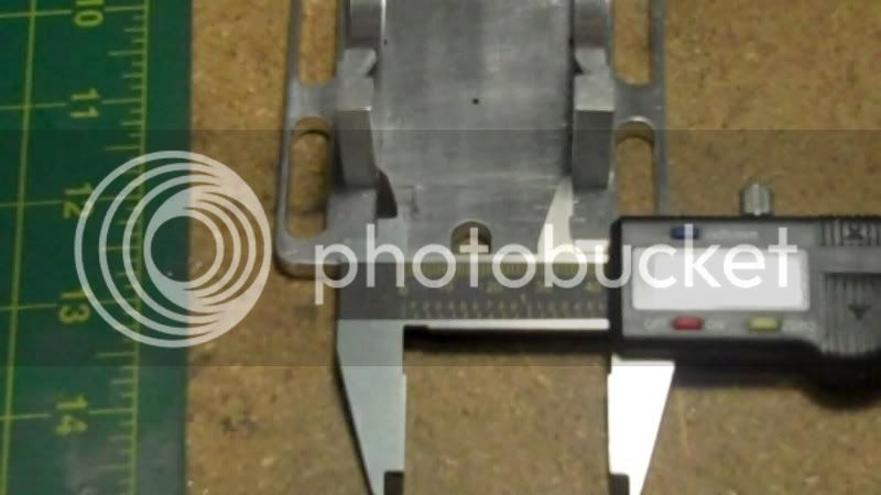
then checking for hole alignment I used a compass to draw a 1/2' circle to represent the final bore size for my model
the original bore size is 1" so to keep to scale I using 1/2"
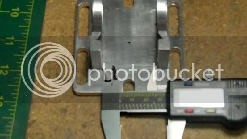
Now to make sure I know when to stop the bore so as to keep the leftover material intact, I need one last measurement of the thickness of the workpiece.
Now even though I used the top edge of the original vise to get the dimensions to locate the bore,
I will now use the bottom of the workpiece to do all edge finding
and secure dimensions
to do all the machining.
The reason for this is because when I layout the nut block to get it in the right position, so the holes line up with the center of this bore, I will need to use the bottom of the block to reference off of, the top has no bearing on this matter seeing it is sticking up in the air and not grounded to anything with the piece it mates to.
But the bottom of both workpieces have a common ground.
machining operation begins
Now if I can I like to make a locating hole as soon as possible before any major work is done
since I'll be tapping with a 10-32 thread I can use a #21 bit to satisfy the locator hole.
Now I better check and make sure this hole did NOT get into the dovetail portion,, how acurate was my layout, well I can only tell by using a mirror to get underneath all this stuff to take a look
UH OH, OH NO, that hole is pretty close to the dovetail, AHH, did I mess up that much,
lets see how the original looks
WHEWWW, the original has its clearance hole close to its dovetail too, OK, then looks like it is close to scale at this point, so it should be ok then.
OK now I can set the depth of cut
Nope can't use these largish dia. drill bits, I wanted to use a 31/64 drill bit drill to specific depth, then ream to 1/2" diameter, buuuuttt, the depth I'm going is only around 1/4" and the large dia. bits have there large flutes in that area, I need a round flat bottom hole,
OK, I'll use these
start out small, and work my way up to 1/2" dia.
Now that the depth stop is set, I'll need to lacate the 'Z' axis for each change of endmill.
and away we go...
glad that's done.
see the slot at the top to allow the dovetailed washer to bear against the slide.
Here, see if this shows it better.....
alright how about this way.....does it show more that way...
it is probably hard to tsee itl, but I'm sticking a 1/2" piece of rod into the bore, to check for it protruding through the interior dovetail..
As the top portion is in position, you can see it's dovetailed slide through this clamping slot.
and this part is acomplished, Thank GOD...
Thanks for looking in,
Have fun in the shop..
- Joined
- Jul 16, 2007
- Messages
- 2,993
- Reaction score
- 1,061
Hi Hobby,
I have been following your thread from day one. You are doing a great job on an interesting project but I must ask, what kind of camera are you using? Is there a macro adjustment or some kind of close up setting that you could use? It's a shame to document your entire build with 'fuzzy' pictures. Sometimes it's just a matter of hitting the right button to help with the focus.
At any rate, keep up the good work and I will still be following along.
gbritnell
- Joined
- Dec 5, 2009
- Messages
- 510
- Reaction score
- 47
Hi George,
Thankyou very much for the compliment, and thankyou, for folowing along in this thread, it means a lot to me.
The camera I am using is my "flip video" camera, I can take a couple seconds shot of video, (I try to hold everything still during these shots just as if I were using a still photography camera), and then I use the program that is built inside it, that automatically is installed on my computer, to use the option of "snapshot" it allows me to replay the video, then stop it and save it as a snapshot, the camera I believe is very good in clarity, when I take videos from a normal distance, it seems like it is the very closeups, that get all fuzzy.
I think I know how to remedy that, instead of bringing the camera real closeup to the subject, I should keep the normal distance, and use it's zoom lens feature, I think that may work better.
I do have a cable power adaptor coming for my 10 yr. old digital camera, but It is very difficult to use, because the button is on the right side, and I do most of my snapshots holding the camera in my left hand, so as to have my right hand available to do the shopwork.
So I really would like to keep on using my video camera, which when put on it's stand I can have both hands available for shop work,, so hopefully by using the zoom feature, it would make the closeups more clearer, if not than I'll go back to my digital camera with the power cable.
I'll have to play around with this in this thread.
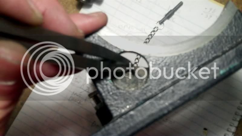
I was wondering I made some videos in this thread also, I don't know if anyone really wanted to view them or not, mainly because it looks like you have to click on a link to bring up my youtube channel, and I personally know that when I see those links, I don't bother to watch them, because they take so long to get to the video, but if there is a youtube video picture embeded right in the persons post, I always click on it, knowing it would start up quickly.
I don't know why my youtube links don't put a picture embeded into my posts, instead it always puts a link to my chennel, that's enough to deter people from bothering to look at it.
But these links do bring up the video very quickly, because they are embeded in my posts.
Thanks again for following along,
George, you and quite a few other people on here, are a great inspiration to hobby machining, it's because I see how you take the time to set up your RT, even if its for a few operations only, then reset your vise back on the table, it's seeing how you take that extra effort, and your builds exceeds all these efforts, with magnificent results.
It is these small things you show in your post, that makes me want to take the extra time and effort to go that extra distance to produce results above the ordinary, ordinary for me are square corners, no filling or sanding but abstract block construction, with mechanical movements.
So thanks for how you share your talents with us, and give us that extra boost to take our machining to the next level.
Thankyou very much for the compliment, and thankyou, for folowing along in this thread, it means a lot to me.
The camera I am using is my "flip video" camera, I can take a couple seconds shot of video, (I try to hold everything still during these shots just as if I were using a still photography camera), and then I use the program that is built inside it, that automatically is installed on my computer, to use the option of "snapshot" it allows me to replay the video, then stop it and save it as a snapshot, the camera I believe is very good in clarity, when I take videos from a normal distance, it seems like it is the very closeups, that get all fuzzy.
I think I know how to remedy that, instead of bringing the camera real closeup to the subject, I should keep the normal distance, and use it's zoom lens feature, I think that may work better.
I do have a cable power adaptor coming for my 10 yr. old digital camera, but It is very difficult to use, because the button is on the right side, and I do most of my snapshots holding the camera in my left hand, so as to have my right hand available to do the shopwork.
So I really would like to keep on using my video camera, which when put on it's stand I can have both hands available for shop work,, so hopefully by using the zoom feature, it would make the closeups more clearer, if not than I'll go back to my digital camera with the power cable.
I'll have to play around with this in this thread.
I was wondering I made some videos in this thread also, I don't know if anyone really wanted to view them or not, mainly because it looks like you have to click on a link to bring up my youtube channel, and I personally know that when I see those links, I don't bother to watch them, because they take so long to get to the video, but if there is a youtube video picture embeded right in the persons post, I always click on it, knowing it would start up quickly.
I don't know why my youtube links don't put a picture embeded into my posts, instead it always puts a link to my chennel, that's enough to deter people from bothering to look at it.
But these links do bring up the video very quickly, because they are embeded in my posts.
Thanks again for following along,
George, you and quite a few other people on here, are a great inspiration to hobby machining, it's because I see how you take the time to set up your RT, even if its for a few operations only, then reset your vise back on the table, it's seeing how you take that extra effort, and your builds exceeds all these efforts, with magnificent results.
It is these small things you show in your post, that makes me want to take the extra time and effort to go that extra distance to produce results above the ordinary, ordinary for me are square corners, no filling or sanding but abstract block construction, with mechanical movements.
So thanks for how you share your talents with us, and give us that extra boost to take our machining to the next level.
- Joined
- Dec 14, 2007
- Messages
- 1,181
- Reaction score
- 31
You are doing a great job on this project and this thread!
Did you complete the sim?
For photographing in the shop I tapped a piece of 3/8 stock and bottom out a short length of 1/4-20 stud with a jam nut. This screws into the tripod mount of your camera (if it has one) and the 3/8's end is held in a mag base. For bench shots I put the mag base on a heavy block of steel. This really helps to steady the camera.
Have fun!
- Joined
- Dec 5, 2009
- Messages
- 510
- Reaction score
- 47
KustomKB,
Thanks for looking in
and thanks for the suggestion about the camera, I have a tripod for my flip video, it will fit in the digital still camera too, about the "sim" project, it is on hold for now, I am done with all the model engineering aspect of it, (machining, and mechanical design).
But I will work on it later on, which will be making a light weight (maybe balsa wood) structure for it, as the photo shows, it will be a project of model design and building, like those old stick model airtplanes, we used to build back in years yonder...
----------------------------------------------------------------------------------
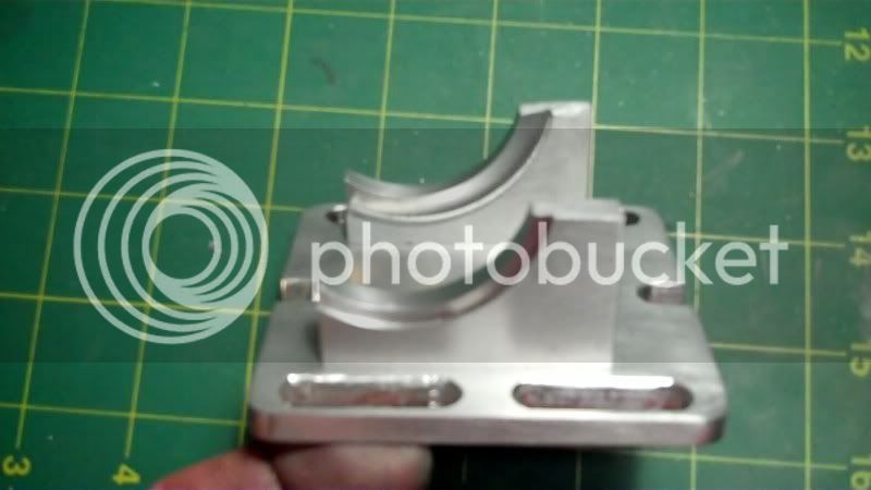
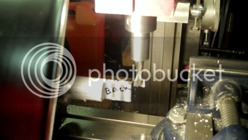
Today I wanted to work on this part of the vice, it is the locking nut housing with a rib connecting to a zero adjustment bolt flange.
I sketched out the relevant positions on the workpiece.
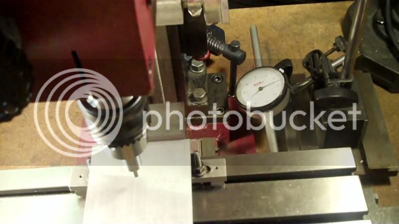
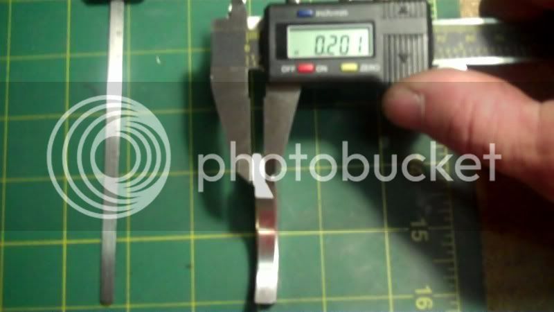
Now I began to take some dimensions, such as the length between the housing and the flange
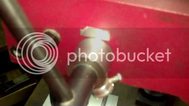
I'll start by taking the depth of cut needed from the backside of the nut housing to the backside of the adjustment bolt flange.
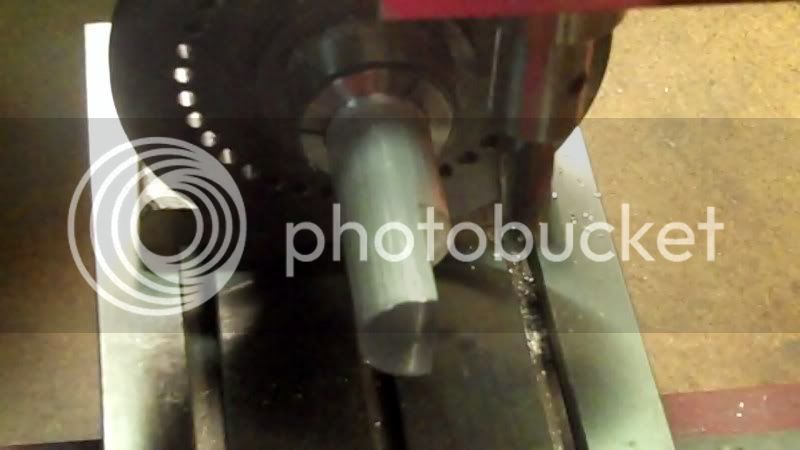
And by taking a 1" diameter round rod (alumminum) and chucking it into my 5C collet spin jig.
I transfer these dimensions to the workpiece.
Touch off and set the 'Z' axis to final depth of cut, on the backside of the workpiece.
Using the backside as a zero reference, on the spin jig.
I now cut to the bolt flange
that would be this area here on the model base.
which is this area here on the original subject.
the back side milled to the flange
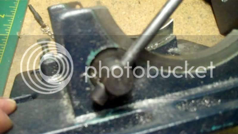
Now that the backside is milled flat, I want to machine a flat bottom, to know how much to machine off I guage the width of the nut housing block from the previous machuined back section to the front, this will determine how far into the round bar I need to machine to get this width cut.
To machune the bottom I turn the spin jig 90* backwards or at the 270* mark shown on the jig.
Now the backside is facing the front, so the bottom side is ontop, ready for machining.
Now with my guage set to the width of the nut housing, from previous measurement, I can now mark the front side of the workpiece using the dividers referenced off the back edge, (which is now at the fromt in this photo), by making a mark, like this
it establishes the width of the nut housing, as well as the depth of cut needed to attain that width
.
So now I can set the depth of cut to this mark.
And machine away the material needed to establish the bottom section.
Now to recap,
I set the jig to 270*
to machine the bottom side,
I set the jig to 0*
to machine the back side.
I set the jig to 90*
to machine the top side
and set the jig to 180*
to machine the front side.
Now I spin the jig so that the front side is ontop .
so it can be machined to final width in dimensioin
which will end up here on the model
Now I need to secure the heigth dimension of the nut housing
and transfer that dim. to the workpiece

set the depthstop to that mark
and machine away the material to bring the top height in.
that is this area here (the heigth dimension) on the original.
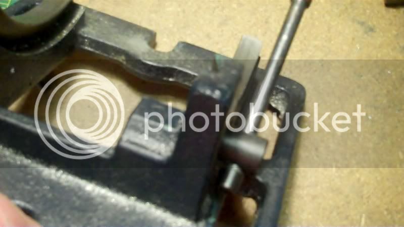
Now I establish the length of the nut housing and transfer that dimension to the workpiece
that mark will be the start of the machining of the connecting rib shown here on the original
I need to get another dimension, and that is to scale down this width of the rib, on the original
transfer the last two dimensions to the workpiece, this will establish the heigth, length and width of this rib feature.
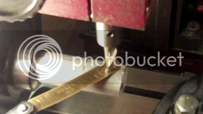
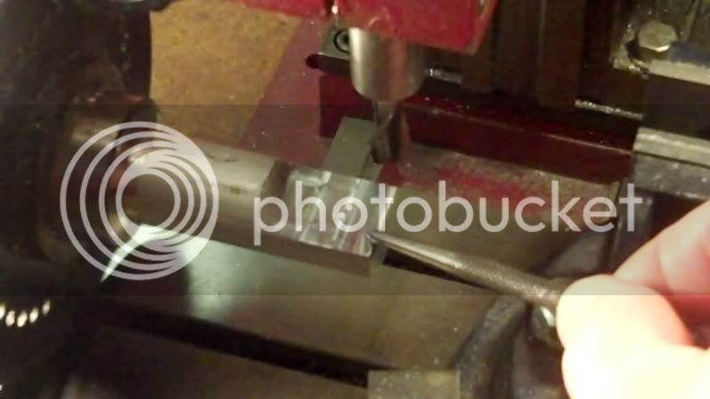
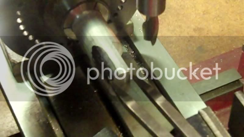
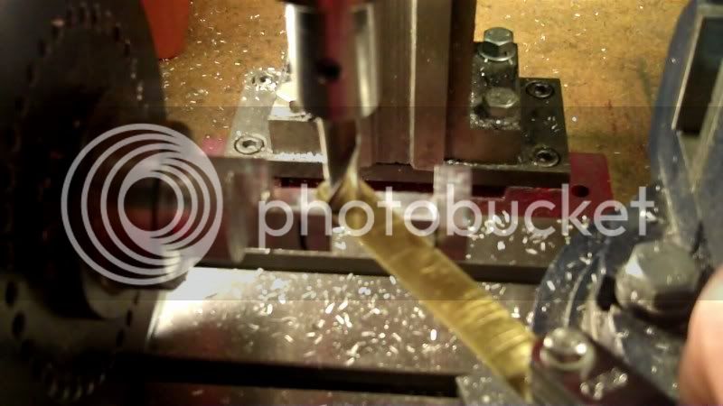
Now to make the start position of this rib, I take a little at a time on the 'Y' axis and using an endmill, I drive the 'Z' axis into the workpiece, about 50 thou. of 'Y' travel for each plunge of 'Z'

Then work the 'X' axis across to make the entire rib length. This is the front of the rib section being machined out.
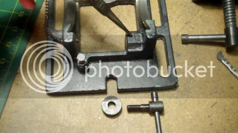
Now that plunge cut at the nut housing intersection, left a rounded interior edge, so the nice thing about a spinjig setup, is I can rotate the jig to make this side be ontop so as to machine that rounded edge to a square corner.
Did I mention, I like to use my spin jig, for complicated workpieces like this.
Rather than a vice. When facets need to be machined on 2 or more sides.
likje this
now the top of the rib machined to final heigth.
looking at the original, the zero adj. bolt flange is at the same heigth as the top of the rib
So I'll take a transfer measurment of the length of this whole section
and transfer that as a mark on the workpiece
as well as the final distasnce between the nut housing and bolt flange
and transfer that mark on here
and now the finish dimensional milling to bring everything into specs.
done to this point
Now machine the end to finished length,
to temporarily c heck for finish fit in the model
Next will be some filling and profile work on this piece, then probably work on the rest of the base, and work my way up to the top section, all the lathe work I'll save for last.
Have a great day..
Thanks for looking in
and thanks for the suggestion about the camera, I have a tripod for my flip video, it will fit in the digital still camera too, about the "sim" project, it is on hold for now, I am done with all the model engineering aspect of it, (machining, and mechanical design).
But I will work on it later on, which will be making a light weight (maybe balsa wood) structure for it, as the photo shows, it will be a project of model design and building, like those old stick model airtplanes, we used to build back in years yonder...
----------------------------------------------------------------------------------
Today I wanted to work on this part of the vice, it is the locking nut housing with a rib connecting to a zero adjustment bolt flange.
I sketched out the relevant positions on the workpiece.
Now I began to take some dimensions, such as the length between the housing and the flange
I'll start by taking the depth of cut needed from the backside of the nut housing to the backside of the adjustment bolt flange.
And by taking a 1" diameter round rod (alumminum) and chucking it into my 5C collet spin jig.
I transfer these dimensions to the workpiece.
Touch off and set the 'Z' axis to final depth of cut, on the backside of the workpiece.
Using the backside as a zero reference, on the spin jig.
I now cut to the bolt flange
that would be this area here on the model base.
which is this area here on the original subject.
the back side milled to the flange
Now that the backside is milled flat, I want to machine a flat bottom, to know how much to machine off I guage the width of the nut housing block from the previous machuined back section to the front, this will determine how far into the round bar I need to machine to get this width cut.
To machune the bottom I turn the spin jig 90* backwards or at the 270* mark shown on the jig.
Now the backside is facing the front, so the bottom side is ontop, ready for machining.
Now with my guage set to the width of the nut housing, from previous measurement, I can now mark the front side of the workpiece using the dividers referenced off the back edge, (which is now at the fromt in this photo), by making a mark, like this
it establishes the width of the nut housing, as well as the depth of cut needed to attain that width
.
So now I can set the depth of cut to this mark.
And machine away the material needed to establish the bottom section.
Now to recap,
I set the jig to 270*
to machine the bottom side,
I set the jig to 0*
to machine the back side.
I set the jig to 90*
to machine the top side
and set the jig to 180*
to machine the front side.
Now I spin the jig so that the front side is ontop .
so it can be machined to final width in dimensioin
which will end up here on the model
Now I need to secure the heigth dimension of the nut housing
and transfer that dim. to the workpiece
set the depthstop to that mark
and machine away the material to bring the top height in.
that is this area here (the heigth dimension) on the original.
Now I establish the length of the nut housing and transfer that dimension to the workpiece
that mark will be the start of the machining of the connecting rib shown here on the original
I need to get another dimension, and that is to scale down this width of the rib, on the original
transfer the last two dimensions to the workpiece, this will establish the heigth, length and width of this rib feature.
Now to make the start position of this rib, I take a little at a time on the 'Y' axis and using an endmill, I drive the 'Z' axis into the workpiece, about 50 thou. of 'Y' travel for each plunge of 'Z'
Then work the 'X' axis across to make the entire rib length. This is the front of the rib section being machined out.
Now that plunge cut at the nut housing intersection, left a rounded interior edge, so the nice thing about a spinjig setup, is I can rotate the jig to make this side be ontop so as to machine that rounded edge to a square corner.
Did I mention, I like to use my spin jig, for complicated workpieces like this.
Rather than a vice. When facets need to be machined on 2 or more sides.
likje this
now the top of the rib machined to final heigth.
looking at the original, the zero adj. bolt flange is at the same heigth as the top of the rib
So I'll take a transfer measurment of the length of this whole section
and transfer that as a mark on the workpiece
as well as the final distasnce between the nut housing and bolt flange
and transfer that mark on here
and now the finish dimensional milling to bring everything into specs.
done to this point
Now machine the end to finished length,
to temporarily c heck for finish fit in the model
Next will be some filling and profile work on this piece, then probably work on the rest of the base, and work my way up to the top section, all the lathe work I'll save for last.
Have a great day..
- Joined
- Dec 5, 2009
- Messages
- 510
- Reaction score
- 47
Today I attached the nut housing / bolt flange, to the model base.
with 1-64 screws at the bottom of the base
then with everything in place I traced out the outline
to mimick the void in the original
with it all marked out
I drilled the start and stop holes
And cut out the interior with a 3/16" endmill
Then took it aside to do some filling work to the base .
and the nut housing / bolt flange
and the tilting angle.
Now I'll take my time to do the finish work on the pieces, as well as the other items to machine to put on this model. The locking mechanism, and the leadscrew, and stabilizer bar. ect...
Have fun in the shop..
Looking really good!!
zeeprogrammer
Well-Known Member
- Joined
- Mar 14, 2009
- Messages
- 3,362
- Reaction score
- 13
Beautiful work hobby.
- Joined
- Dec 5, 2009
- Messages
- 510
- Reaction score
- 47
Steve, Dave, Carl
Thankyou guys, for the compliments, it's much appreciated...
------------------------------------------------------------------------
I did some small work on the base of the model today.
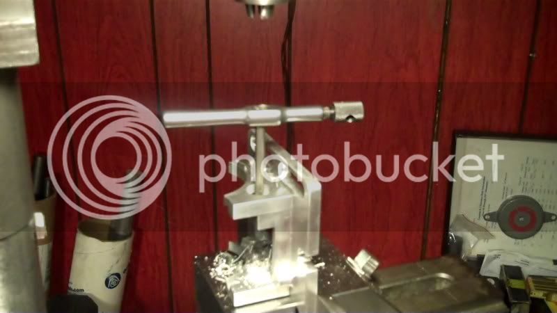
I drilled and tapped for 10-32 thread for the locking mechanism,
I put the whole model base assembly in the vice on my drill press, and used the 1/2" endmill I used earlier to CB this hole, as a line up tool,
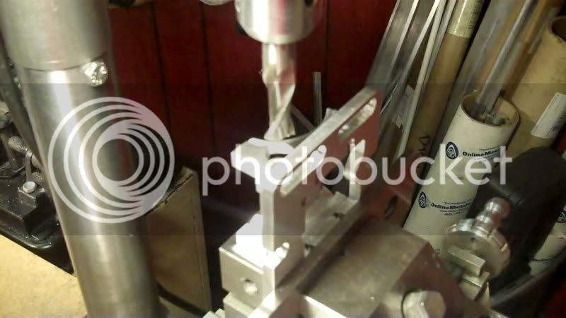
Then drilled and tapped.
Now here I needed to use my CAD program,
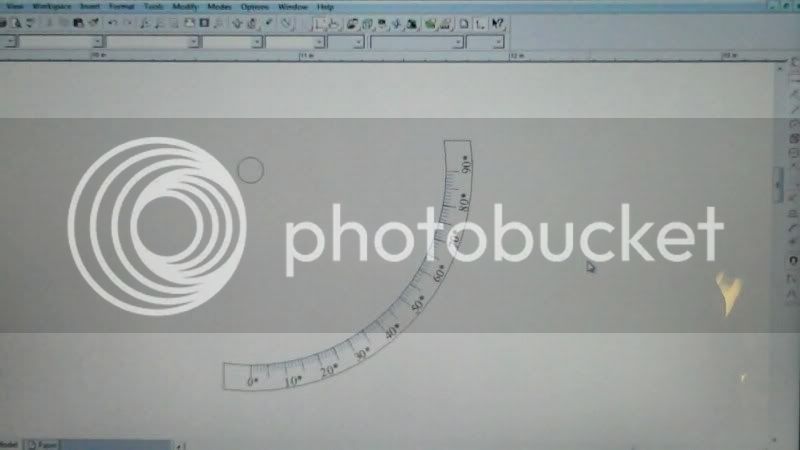
but not for drafting, but for art work,
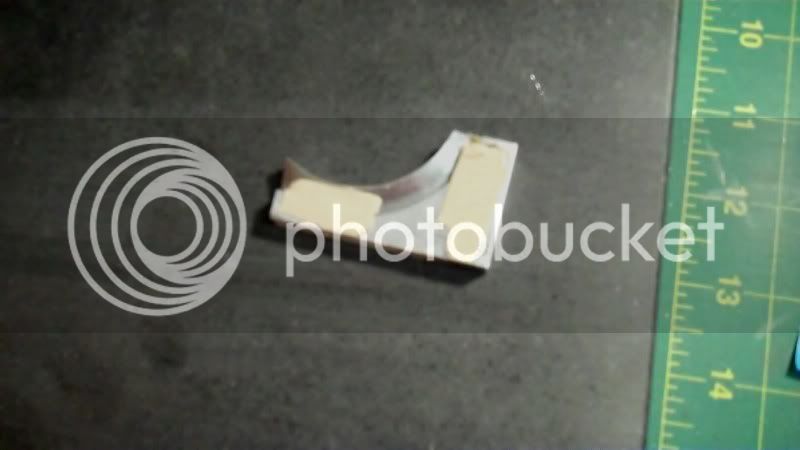
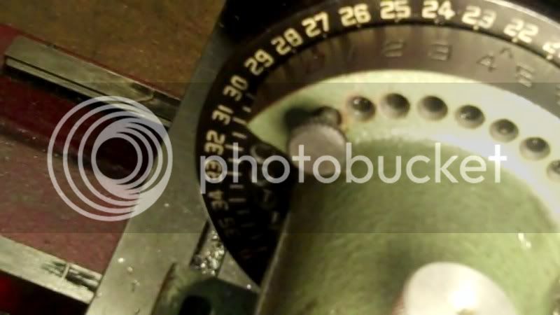
I needed to accurately print out a angle guage,

then to reinforce the printside, I put a piece of clear scotch tape over it,
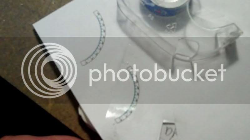
then using JB WELD I glued it on to the model base
I'm working on the base of the model first before I move up to the vise part.
Probably the next thing would be to make the locking mechanism, so as to be able to lock it in posistion as I drill the index holes on the gauge side.
Than the base part would be done on this model.
Have fun in the shop...
Thankyou guys, for the compliments, it's much appreciated...
------------------------------------------------------------------------
I did some small work on the base of the model today.
I drilled and tapped for 10-32 thread for the locking mechanism,
I put the whole model base assembly in the vice on my drill press, and used the 1/2" endmill I used earlier to CB this hole, as a line up tool,
Then drilled and tapped.
Now here I needed to use my CAD program,
but not for drafting, but for art work,
I needed to accurately print out a angle guage,
then to reinforce the printside, I put a piece of clear scotch tape over it,
then using JB WELD I glued it on to the model base
I'm working on the base of the model first before I move up to the vise part.
Probably the next thing would be to make the locking mechanism, so as to be able to lock it in posistion as I drill the index holes on the gauge side.
Than the base part would be done on this model.
Have fun in the shop...
Similar threads
- Replies
- 413
- Views
- 42K