1/2: scale model of my angle vise build

Home Model Engine Machinist Forum

Help Support Home Model Engine Machinist Forum:

This site may earn a commission from merchant affiliate links, including eBay, Amazon, and others.

hobby

Project of the Month Winner!!!
Project of the Month Winner
Joined
Dec 5, 2009
Messages
510
Reaction score
47
Hello everyone,

I'm going to try to build a 1/2 scale model of my angle vise.
I am not a seasoned scale modeler so this is all new to me.
The original is casted from a mold, so I will have to machine certain parts and either screw or dowel them together.
I am going to try to make as much as possible to scale, that is in my capability.

This is going to be a fun challenge, because of the radial dovetailing that needs to be done.
I am also going to try to use only my drafting board and supplies, for all my drawings, and not my CAD program.

Here is the original vise,

100_2732.jpg


the starting of the drawings for the dovetailing to be done on the vise body.

100_2733.jpg


100_2734.jpg

Thanks for peeking in.

Have a great day.
 
What a great way to dust off the old drafting skills. I always used to prefer pencil and paper to CAD, but that was back when CAD was still getting its feet. I should try and draw something by hand again some day....used to win state awards in high school.

Enjoy the build, I'll be following along!

- Ryan
 
Interesting project. I will be looking forward to your progress
 
Hobby,

Hand drafting................I take my hat off. :bow: :bow:

I was never so happy as when CAD came along and after some time I could produce a drawing which did not look like a page of fly droppings, (which all of my hand drawn ones did i.e. between 1958 and 1998).
 
Ryan,
It takes a little getting use too, after using a CAD all the time, it seems like after I make a change on my drafting board (eraser and pencil), I'm looking for the save button, so I can resave my work.
I'm not kidding, I find myself wanting to click a mouse button somewhere to save the editing.
Thanks for following along.

Herbiev,
Thankyou, for looking in, and following along.

Maryak,
I'm sure your drawings could not be that bad.
The CAD programs are nice, but there getting too expensive to have to buy, should you need to upgrade to work on the more modern computers.
My turbo cad ver. 9 was the last upgrade, it works well on these new systems.
Thanks for looking in.

-----------------------------------------------------------------
Hello,

I started with a piece of 3" x 4-1/4" x 1" piece of aluminum bar.

1.jpg


After machining it to final dimensions on all 6 sides,
I proceeded to cut it in half on the bandsaw.

2.jpg


3.jpg


Then from there I calculated where the radius pin hole will be drilled on each workpiece, as well as where to put the mounting screws, holes.

4.jpg


5.jpg


After determining these positions, I then referenced the left edge of each workpiece, and using my dial indicators, I located all three holes, and drilled them to required diameter.

6.jpg


Then made a wood faceplate to bolt onto my rotary table, after locating the RT on center, I bolted the faceplate to the RT, and drilled a 5/16" dia. hole on center, to place a locating pin. This pin will be the exact radius center of the operaqtions to follow.
Here i'm making a locating pin.

7.jpg


I then placed the pin in the mill chuck, to press fit it into the hole in the faceplate, so now the pin is centered on the RT.

8.jpg


9.jpg


10.jpg


This shows the 2 workpieces which are drilled, as mirror opposites of eachother, ready to be mounted on the RT.

11.jpg


The middle hole on each piece is the radius center (locator pin), and the 2 outside holes are drilled with aq #21 bit to snuggly fit a all purpose drywall screw into to screw into the wood faceplate.

12.jpg


Now determining the exact distance offset on the y axis.

13.jpg


and the cutting comences, this is the outside radius, being machined.

14.jpg


15.jpg


Now the next piece is the mirror of the first. so it is located and positioned opposite.

16.jpg


Both pieces mirrored of eachother, the first radius cut.

17.jpg


put back the first piece easily located on the pin, everything returns back precisely. do to the locator pin.

18.jpg


and machine the next radius, which is a 1/4' in from the first.

19.jpg


I was using a 3/16" endmill so the second radius cut leaves a small flange, so after cutting both pieces I moved the y axis in 100 thou. and milled off the flange.

20.jpg

both workpieces done to this point.

21.jpg


end the top views of them.

22.jpg


Next I'll need to machine the rest of the material on the outside of it down to a specific thickness, then relocate on the locator pin each workpiec onto the RT, but now I'll need to drill new mounting holes, to screw the workpiece down, because I will need to put the RT, in the vertical position, to do the actual dovetailing detail, the screws are in the way the way it is now.

So next up is the rest of the machining to prepare it for the dovetailing operations.

Have a great day...
 
I do still occasionally sketch things out on isometric graph paper for visualization, and there's basic geometrical layout required in my job, but the last time I did any serious pencil and eraser (and paper) drafting was an inked isometric perspective view of three gears intermeshed- I used no templates, constructing every arc of every isometric circle and gear tooth manually with a compass...took me the better part of my senior year in high school, but it did win me a few state awards in California :)

I really should do something like that again... I miss the good old days of non-CAD drafting.

On topic, keep up the good work =)

- Ryan
 
Hi Ryan,
Wow, that's excellent work to be able to use a compass like that.
Any expert advise I need about drafting I'll know who to look up, on this forum,

You, and Brian R. you both have the expertise, in this area.

I have a hard time using a compass, it always wants to lift the point off of the center, I have to use both hands, one to hold the point on the paper and the other to swing ever so slowly back an forth an arc, as I'm completing a circle, that's why I bought one of those circle templates, to accomodate most of the small circles I have trouble with.
Larger circles or arcs, I have no problem keeping the compass on center, it is the small circles that makes it difficult for me.
----------------------------------------------------


Hello,

I am preparing the side blanks for the dovetailing operation,
I have machined all the predovetail steps, and am now removing the rest of the material in the middle.

23.jpg


According to my drawing, I will need to take the top of the blank off, at a vaqlue of 1" from the bottom of the blank.

24.jpg


So I have made a rough line on the workpiece, and am now going to drill 2 new holes for mounting screws on the wood faceplate.
These holes are drilled above the 1" mark which will eventually be waste.

25.jpg


26.jpg


And now the workpiece is remounted on the RT, with the new screwholes.

27.jpg


And the machining of the outside waste is done to each workpiece.

28.jpg


29.jpg


I then took them out to my bandsaw, and sawed away the rest of the waste material, and then remachined the rest of it to final dimensions, and thickness.

30.jpg


31.jpg


32.jpg


This is what is done so far.

33.jpg


A little more machining, then the workpieces will be mounted on the RT, but this time the RT will be in the vertical position, so as to machine the dovetails in the proper orientation.

Thanks for looking in.
 
Hi,

Now that both pieces are roughed cut with the bandsaw, it is now time to machine all surfaces to final dims.

In order to do that I need a reference to work from.

This side here, is the only area on both pieces, that has gone untouched by the machining operations. So here is what I will use to reference everything from, that and the radius hole drilled in the center.
I used this reference edge to set on the parrallels in the vice, to orient it horizontal with the table.

34.jpg


Now after some calculating I was able to determine the distance on the workpiece, from the bottom round section, to the bottom of the rail, and after touching off with the endmill on this round bottom section, I set the depth of cut with the dial indicator, and locked the depth stop, in the appropriate depth.

35.jpg


And began to mill the underside of the rail on each workpiece.

36.jpg


Now I need to determine where to make the finish length cut on that same rail, so I used the radius hole as the reference point.

37.jpg


Made a reference mark to locate in the mill.

38.jpg


After locating this reference point, with a center finder, my wiggler is to long for this operation, so I had to adjust my center finder and use it to use as a pointer for center of spindle axis.

39.jpg


Next I took a scale measurement to locate the length of this rail, from reference.

40.jpg


And machined to length the rail on each workpiece.

41.jpg


Now I need to machine the top side of the rail, however I can't use the flat reference on the parrallels because it will be sticking up in the vice for this operation, I need to put the bottom side on the parallels to clamp down the workpiec in my vice, but the bottom is rounded over,

42.jpg


it will rock in the vice

43.jpg


Therefor I will still use the top reference edge, but will level out the workpiece by referencing the top reference side parrallel with the table by using 2 squares to insure the top reference edge is square with the table.

44.jpg


Now I use the feeler guage to reference from the top side, for the depth of cut needed on the top of the rails.

45.jpg


And machine the top of the rails to final dimensions.

46.jpg


Now both workpieces are machined to there final dimensions on the surfaces shown.

47.jpg


Now I can return them to the RT, so as to make the dovetailing detail, on them.

The workpiece on the left has a small divet I mistakenly cut to far, so I'll fill it in later on in the build.

Next will be the dovetailing sequence.

Have a great day...
 
loving how you show the problem along with the solution. keep up the great work!

- Ryan
 
Thanks guys for following along.

Hello, here is todays progress.

I returned the RT to my mill, and this time I needed to tram it in on the 'Y' axis, so I used my dial test ind. and a parallel to give the best surface to tram off of.

48.jpg


Then after remonting the workpiece to the RT, using the same reference pin on the faceplate, I used the end of the rail to square up the workpiece,

49.jpg


This was done so as to have the highest point on the botrtom round to be exactly sqare to the table, so I can adjust the 'Y' axis table , to put the exact center of the RT in line with the spindle center line. This is done so the dovetail bit will cut squarely on the workpiece.
And now the cutting of the dovetail begins.

50.jpg


Here is a video of the process also.
http://www.youtube.com/embed/IlGsfpxPxgY"

<object width="560" height="349"><param name="movie" value="http://www.youtube.com/v/IlGsfpxPxgY?version=3&amp;hl=en_US&amp;rel=0"></param><param name="allowFullScreen" value="true"></param><param name="allowscriptaccess"


here it is all finished with the dovetailing detail.

51.jpg


Now this shows where the bottom of the rail is located on the original vise.

52.jpg


And where I need to machine it on my workpiece.

53.jpg


After establishing the depth of cut, and setting the depth guage accordingly.

54.jpg


I have a mark where the endmill needs to stop at the front of the workpiece.

55.jpg


And after the milling is done on the workpieces to establish the rails.

56.jpg


Next I'll need to cut and machine off the reference tab, so as to have a completed rail across the workpiece.

Then after that, I'll need to look at how I can machine the mating dovetails at the base of the vise.

57.jpg


That will require the workpiece to be in the opposite direction from the workpieces already done, when it comes to mounting on the RT.

That's all for today,
Thanks for watching...
 
Hi Hobby,
You're making an interesting project. If I may I would like to offer a suggestion. In some of your pictures I notice you are holding your endmills in a drill chuck. This is not the best way to hold size or get a nice finish. The chucks just don't have enough strength for this kind of work.
gbritnell


George,
Thanks for looking in,
Thanks also, for the suggestion of using a end mill holder, rather than a chuck.
I'm now using my homemade holders, for milling operations.
------------------

Hi,
I now have both of the top vice rails to finished dims.
I am now working on the bottom section halves, these require the dovetails to be cutt radially on the interior of the workpieces.

So I started out by locating the edges of one of the workpieces, using the left bottom edge as the reference point.

575.jpg


I then proceeded to set up a workstop, for automatic location, whenever I remove a workpiece, so I can drill both pieces one after another, for each step of the drilling process.

58.jpg


And drilled and reamed a radius reference hole to locate on the RT.

59.jpg


Here is a good tip:
I have three handwheels in my precence, the 'X' and 'Y' table axis, plus the RT handwheel.
To prevent me from accidentally turning the the table handwheels, when only the RT shouild be turned, I put a couple of bowels over the other handwheels to remind me to not touch them.
I have turned them by accident before, messing up all registration with the RT refernce point.
This prevents that from hapenning any more.

60.jpg


I can now mill out the important radius which will allow the top half of the vise to actually ride upon, for easy angular movement.
This is why I love to make wooden faceplates for my RT.
I can screw on clamps anywhere I want, using wood screws to hold the clamp assemblies in place.

61.jpg


Here is what I mean,
this is the part of the dovetail portion of the top of the vice,

62.jpg


that will ride inside the radius cut in the bottom section here.

63.jpg


here it is temporarily fitted together to check for accurate fit, and slide.

64.jpg


As can be seen in this image, I need the dovetail bit to be in this orientation, with respect to this workpiece, however the cutter will not reach the spindle due to all the leftover material on the workpiece.

65.jpg


So looking at the original vice, it can be seen that the bottom dovetail detailing, has a very short arc, a little more than a 1/4 of a circle, (around 100*) maybe,

66.jpg


So I can shorten the workpiece considerably, which will remove anyu interference it had on the cutter bit. I can remove this portion of the workpiece, to shorten the arc.

67.jpg


So next up is to prepare each workpiece, now for the final dims. and the interior radial dovetailing.

Thanks for watching,
have a great day..
 
Hello,
This is the progress for this weekend,
I finished all the dovetailing on all four workpieces. and they slide together very nice.

Here is one side fitted together, to show the dovetailing detail done to both top and bottom halves.

The image is at the bottom of the post.


Here is a video of the process of making this lower half dovetail.
Since the dovetail bit would not reach the farther side of my RT, I had to either use my smaller RT (4") or just make a extension for my endmill holder.
I decided to make an extension, so the dovetail bit could reach the workpiece.

Here is the video.

<object width="560" height="349"><param name="movie" value="http://www.youtube.com/v/M-Tpo46yiX8?version=3&amp;hl=en_US&amp;rel=0"></param><param name="allowFullScreen" value="true"></param><param name="Next I need to machine off the whole backside of the bottom pieces so as for the top piece to show through.

Thanks, for watching.


Radial dovetailing interior workpiece 0 10 56-18.jpg
 
Hello,
Todays progress has allowed me to finish all the dovetailing and fitting of both top and bottom sections.

To start with this process, I needed to remove all the material here

1-1.jpg


so the top section will show through when fitted together with the bottom section.

So using my depth gauge I was able to determine the amount I needed to machine off the back side of these bottom sections.

2-1.jpg


And the machining proceeded.

3-1.jpg


4-1.jpg


5-1.jpg


From there I needed to machine off the nubs sticking up above the top sections.

6-1.jpg


To produce this.

7-1.jpg


8-1.jpg


Now time to compare it with the original subject. (vice).

9-1.jpg


10-1.jpg


11-1.jpg


And the top and bottom fitted together against the original.

12-1.jpg


OK, time to play around with these pieces and see what kind of designs I can make with them.

13-1.jpg

14-1.jpg

15-1.jpg


And finally the backside (inside) of each assembly.

16-1.jpg


The most challenging part of this project is done, and surprisingly has turned out to be a sucess.

Next will be to start making the rest of the parts and assembling everything.

Have a great day...
 
Thankyou Steve, I appreciate you following along.
I hope I don't make these posts to boring, with a lot of pictures and simple routine explanations, I'm just trying to make the most out of my WIP threads.

---------------------------------------------------------------

Hello,

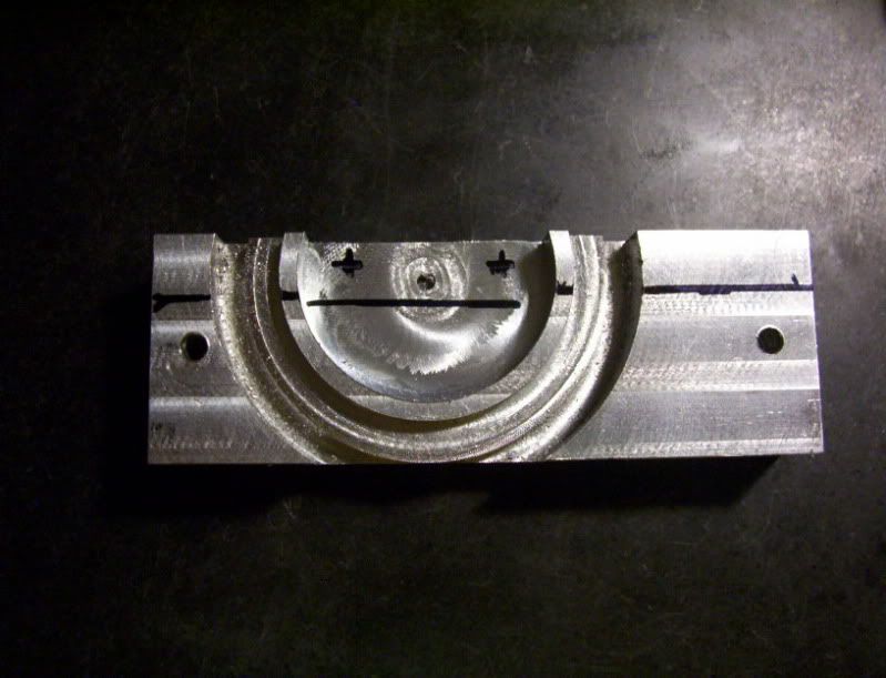
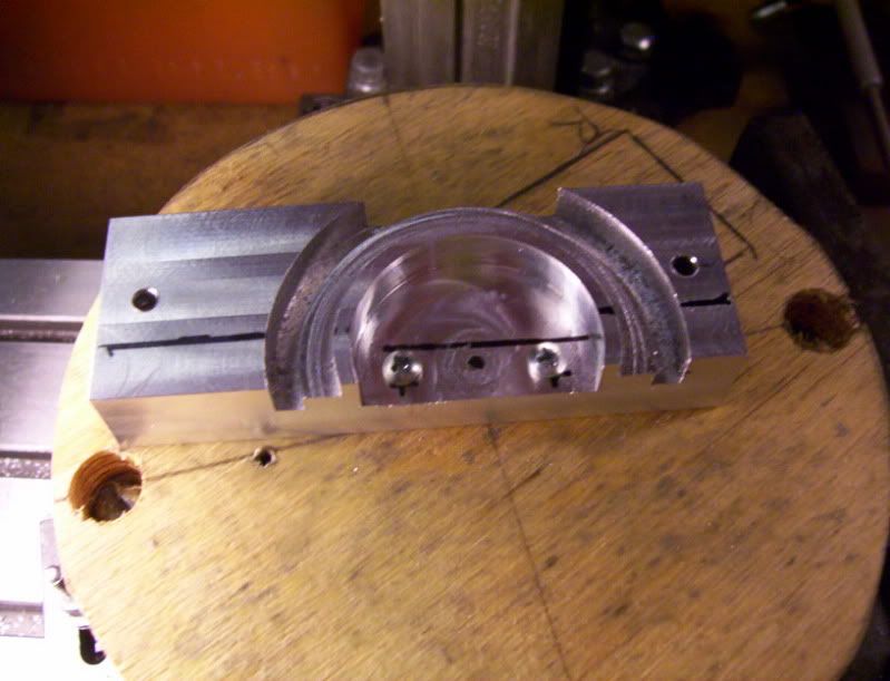
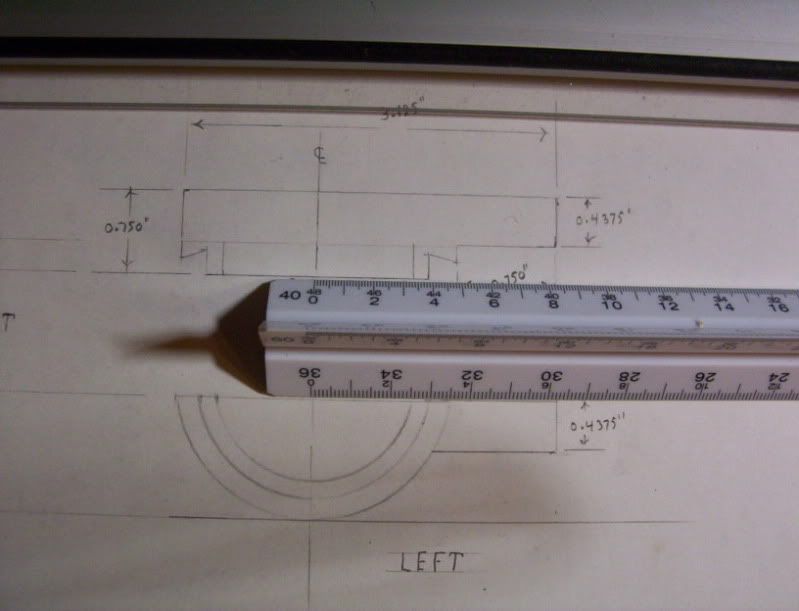
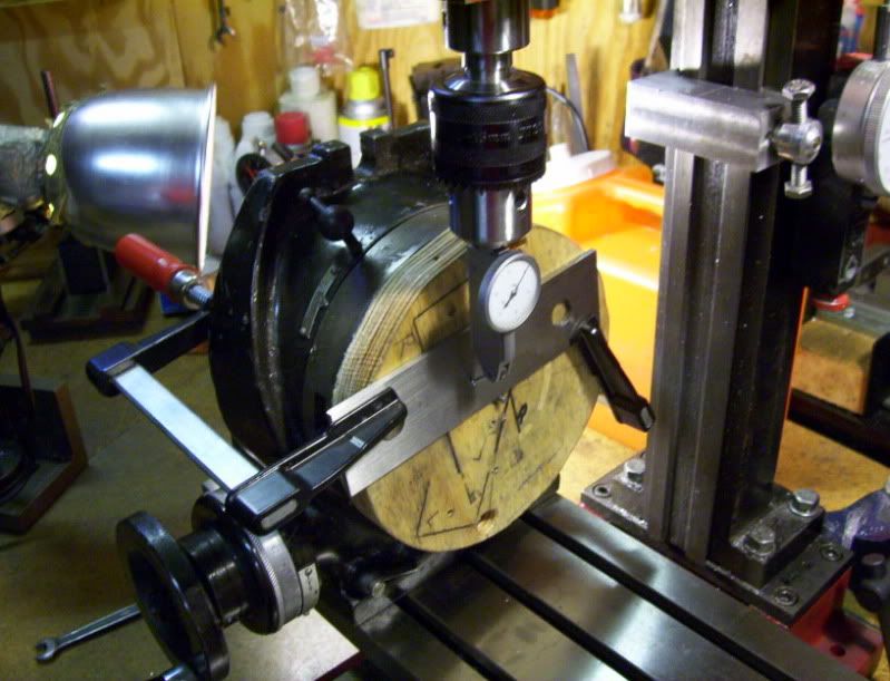
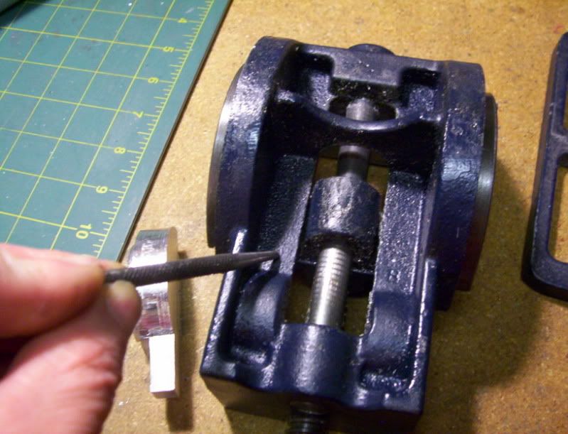
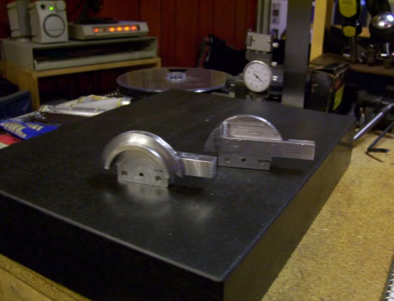
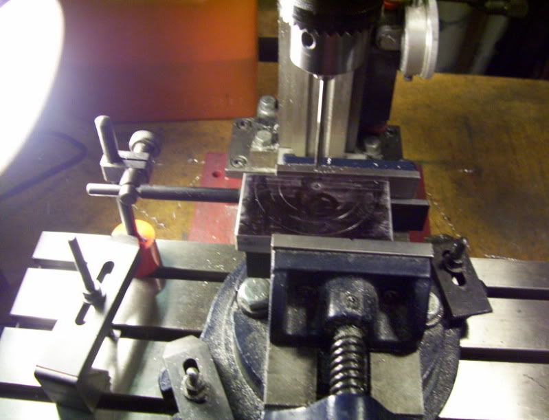
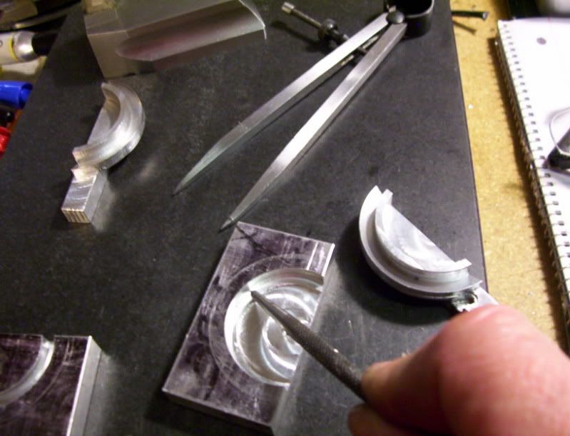
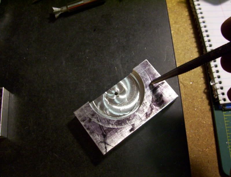
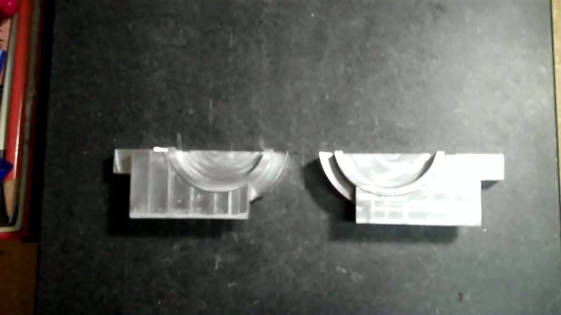
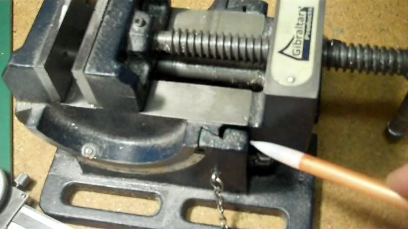
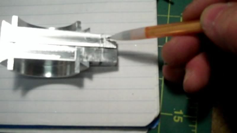
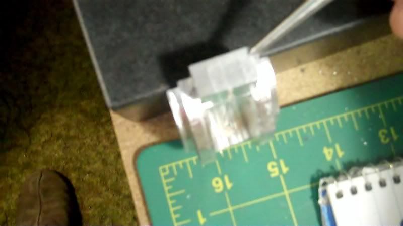
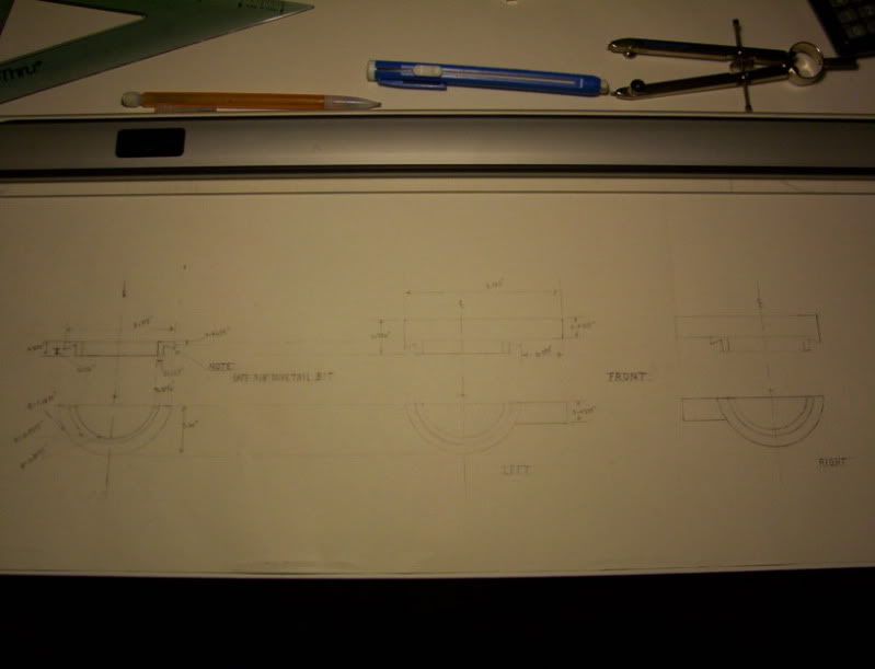
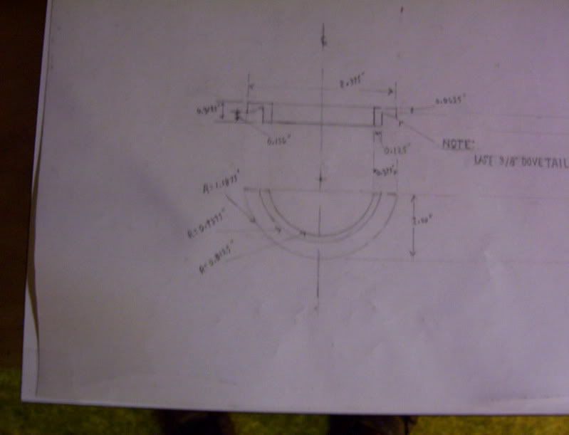
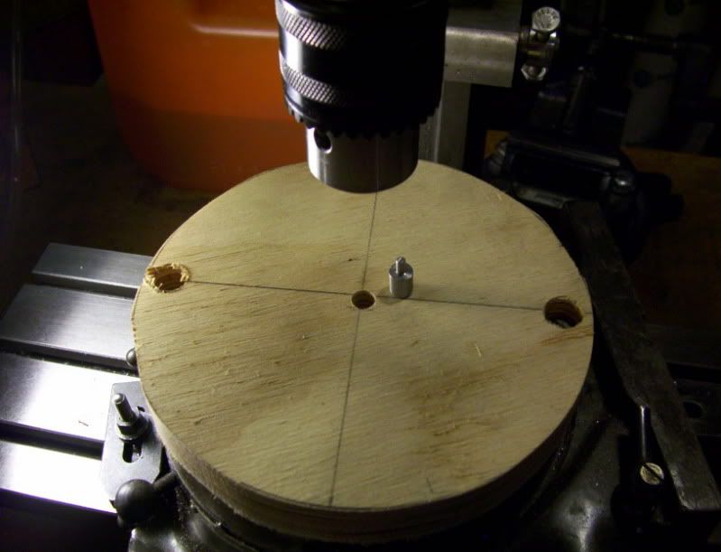
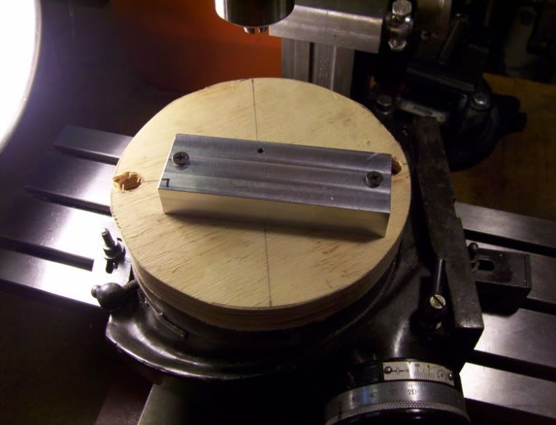
This line marked out here

1-2.jpg


Represents this area here,

2-2.jpg


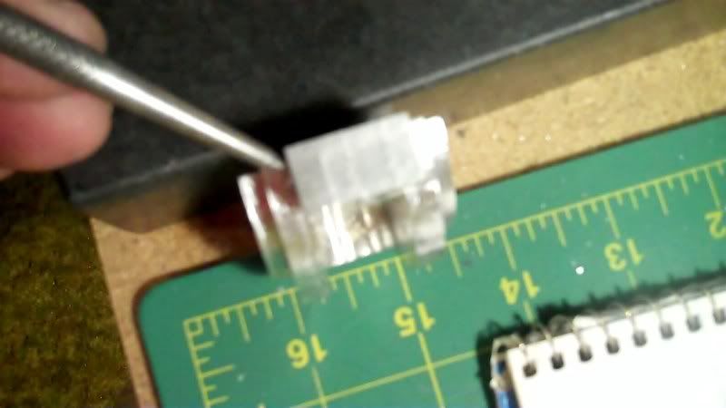
and this small indentation here on the original subject,

3-2.jpg


will need to be machined in this area on the prototype build in this area

4-2.jpg


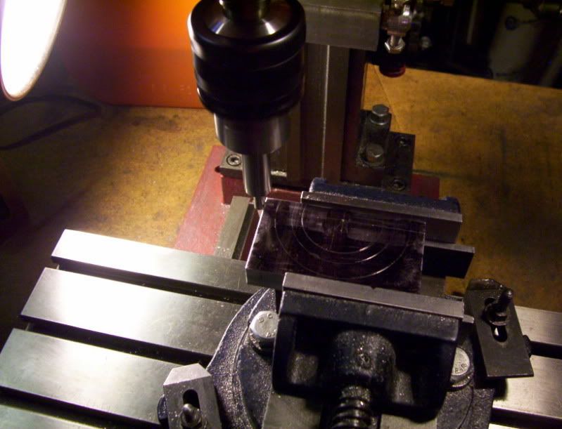
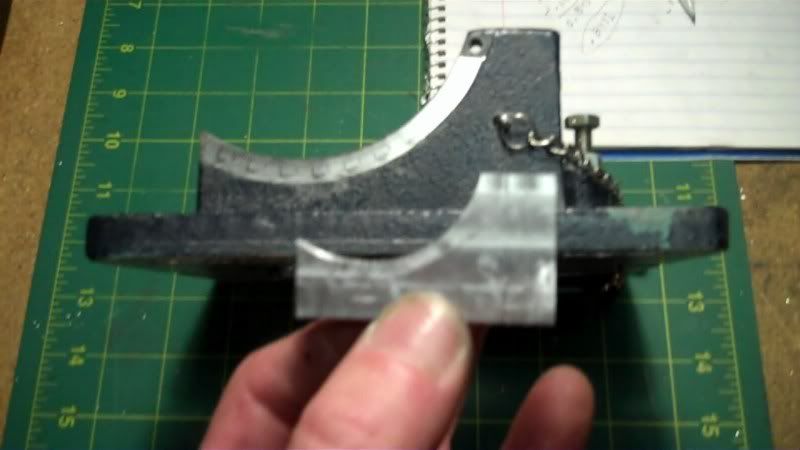
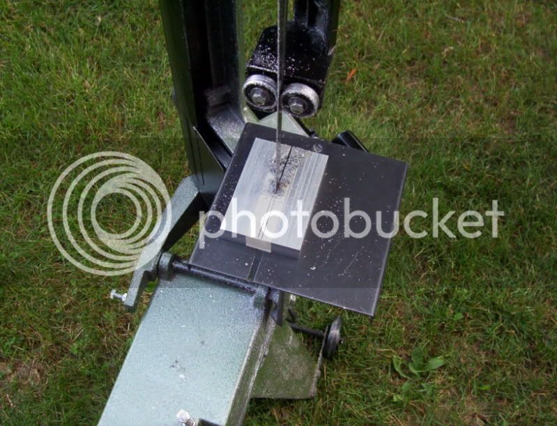
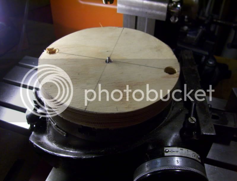
The best way to do this to keep everything consistent is to use double stick tape and after aligning both workpieces tape them together for further machining operations.

5-2.jpg


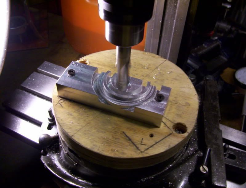
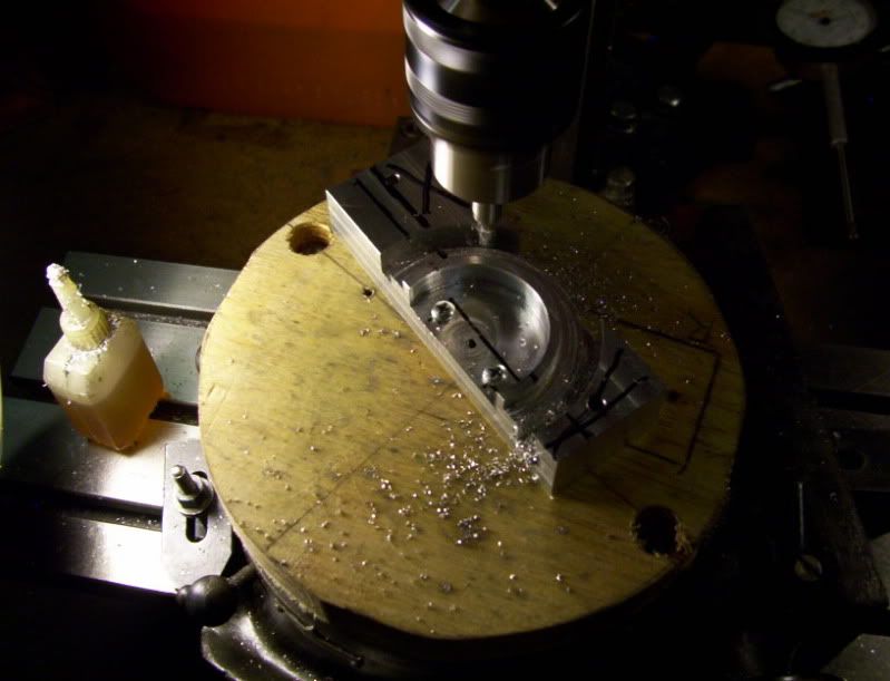
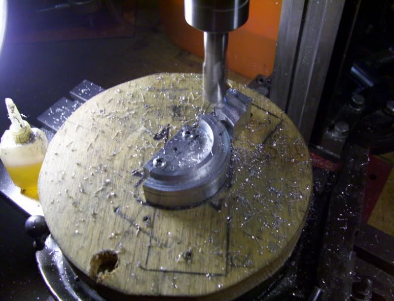
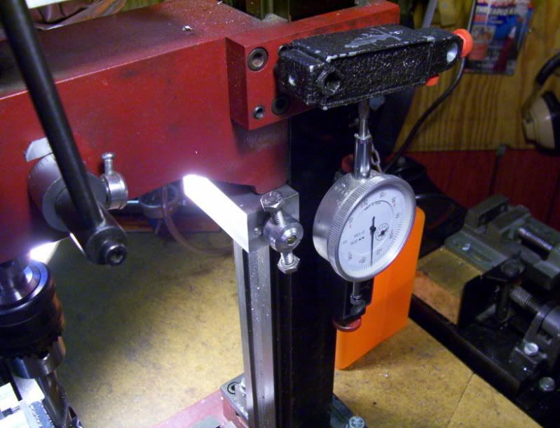
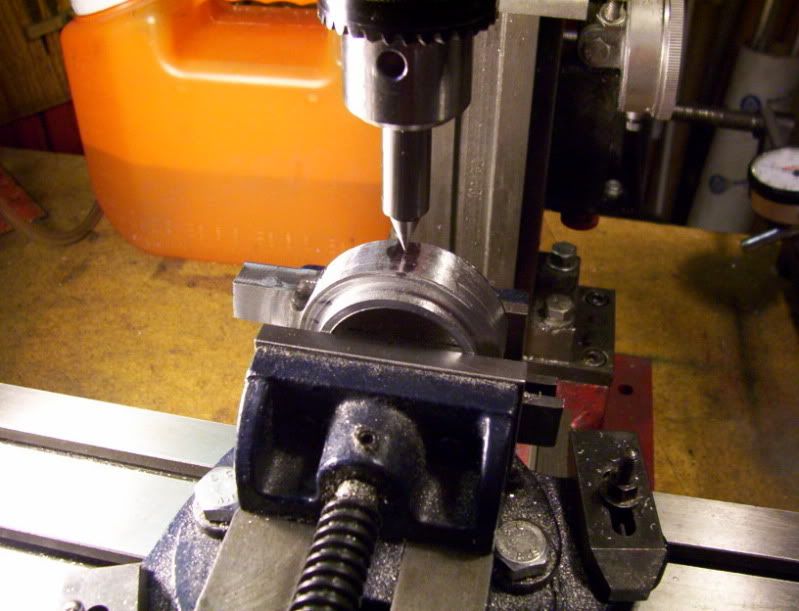
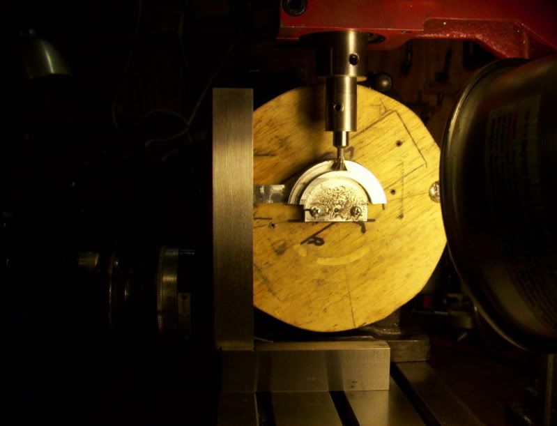
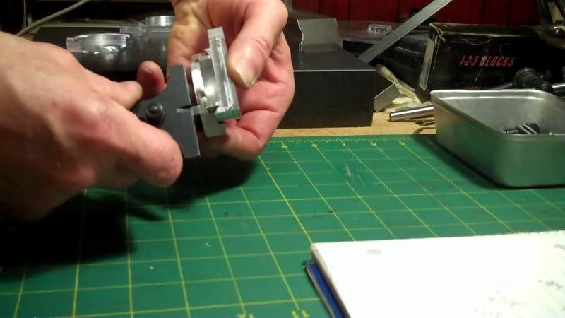
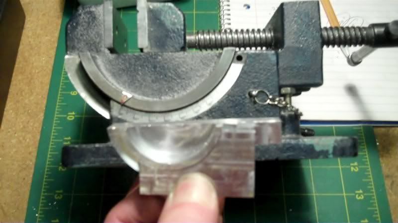
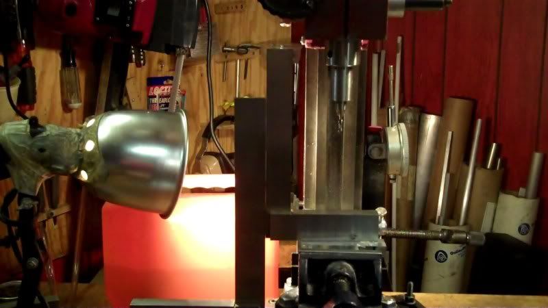
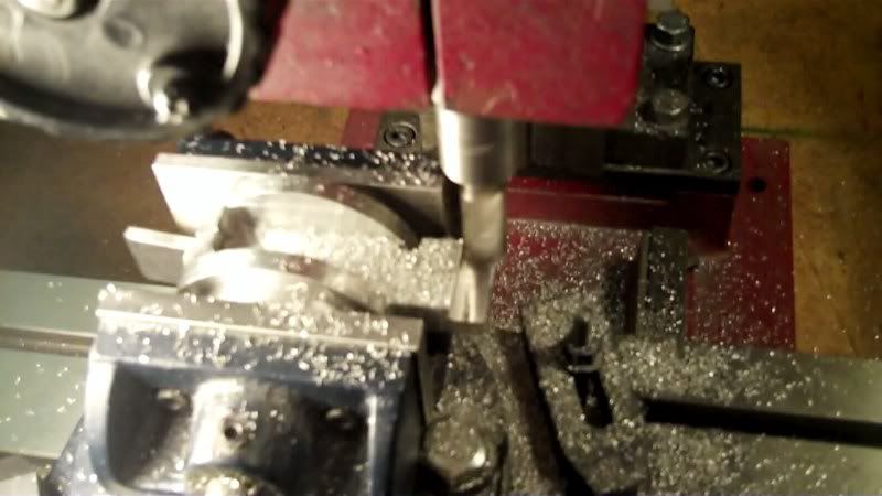
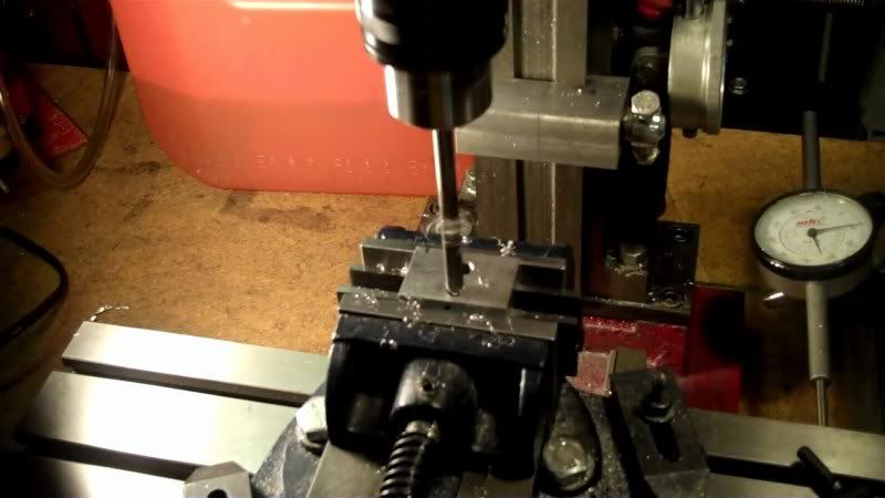
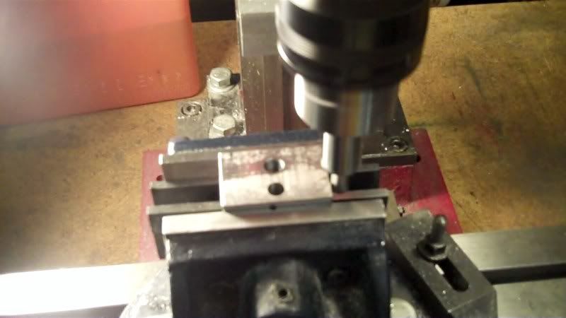
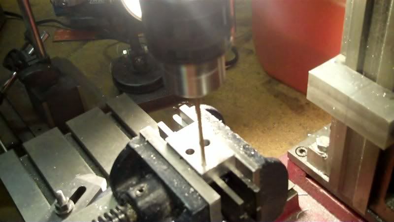
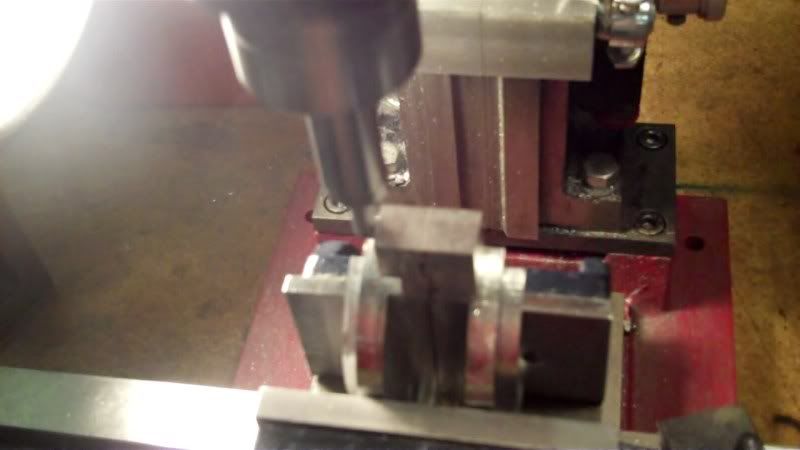
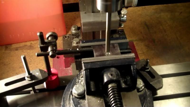
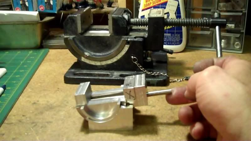
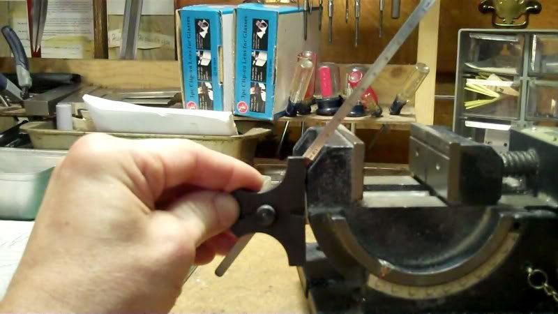
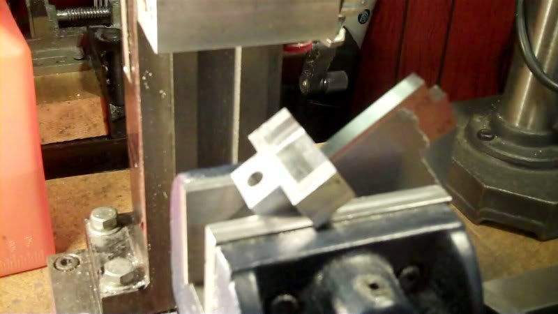
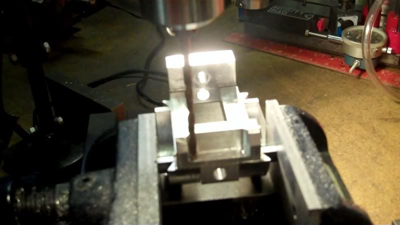
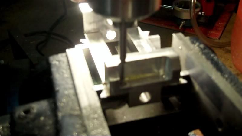
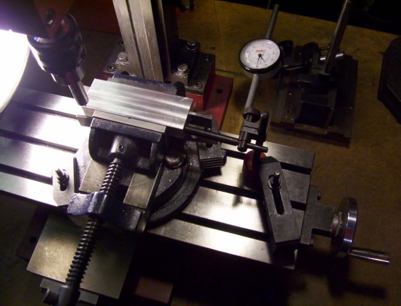
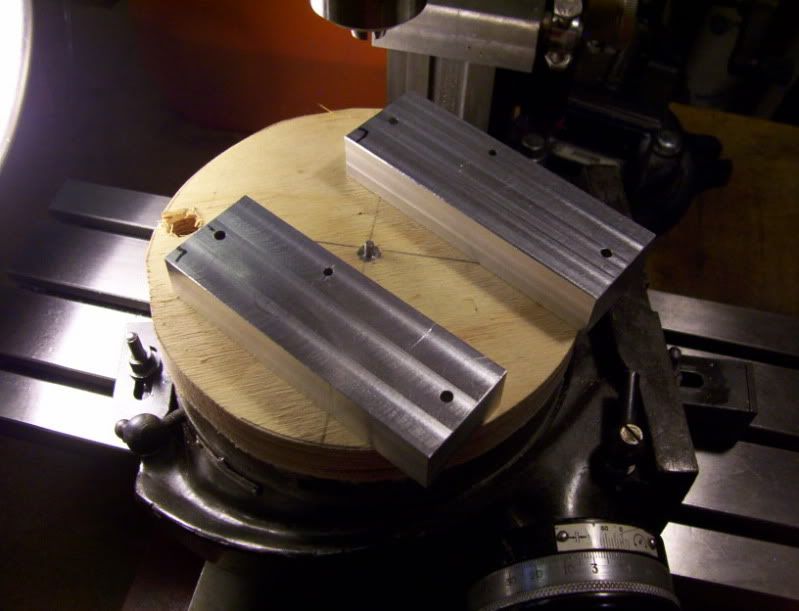
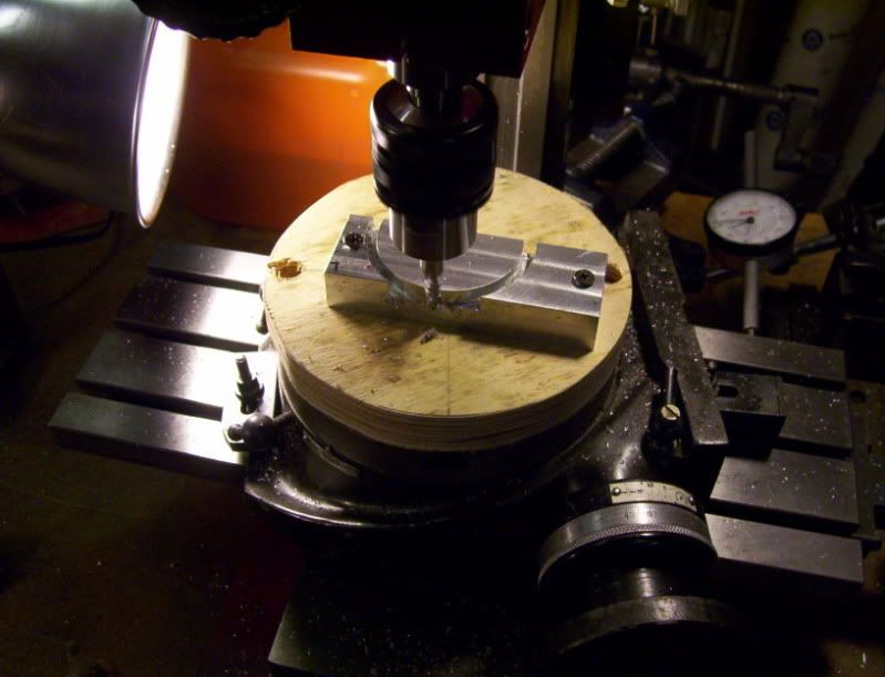
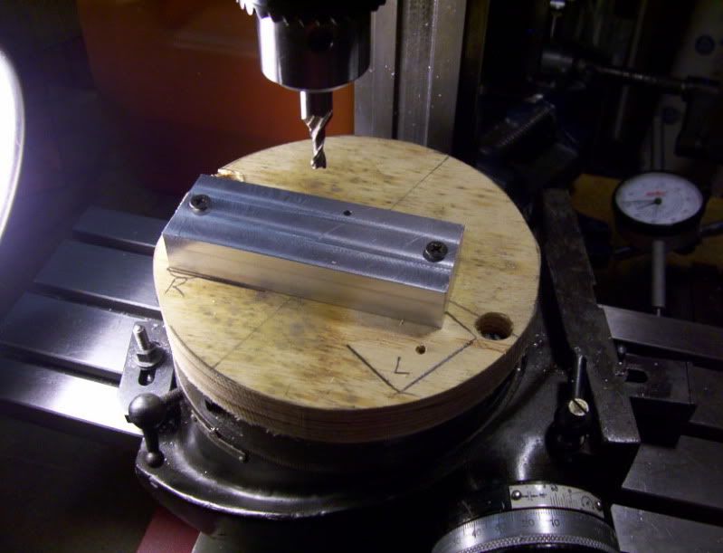
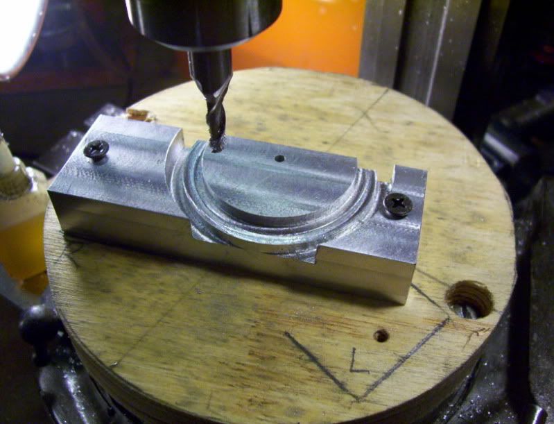
Now to use the old 2 square method to align the flat of the workpieces parrallel to the table

6-2.jpg


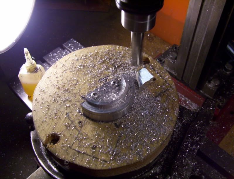
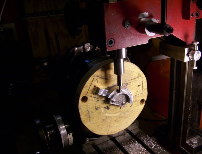
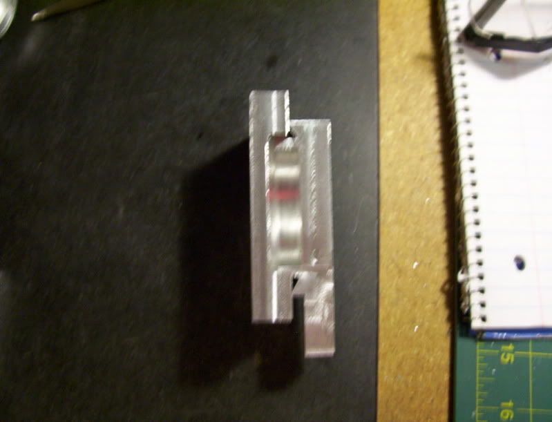
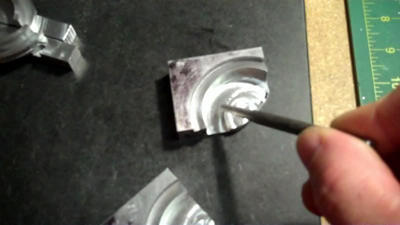
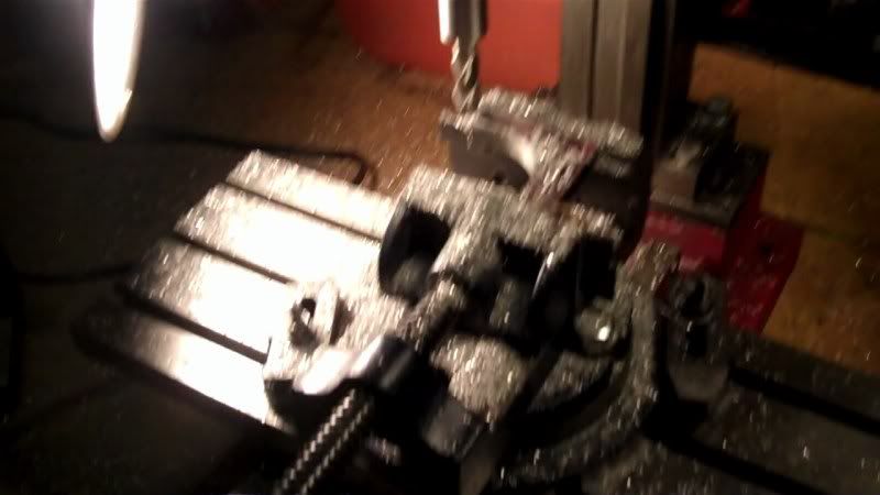
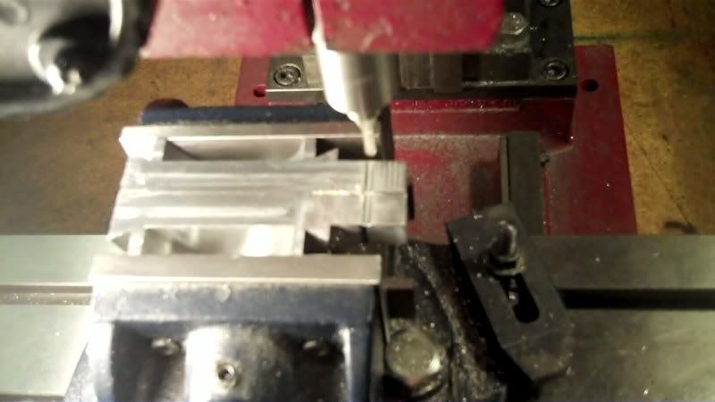
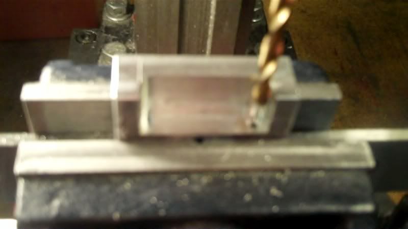
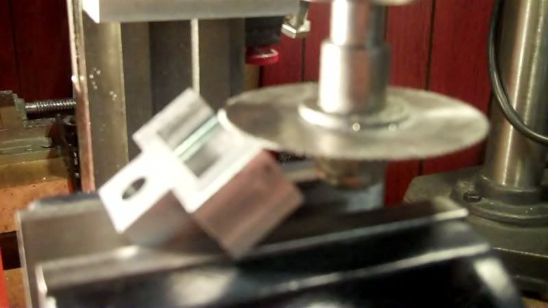
and now using an 1/8" ball endmill, I can start machining that recess into the workpieces.

7-2.jpg


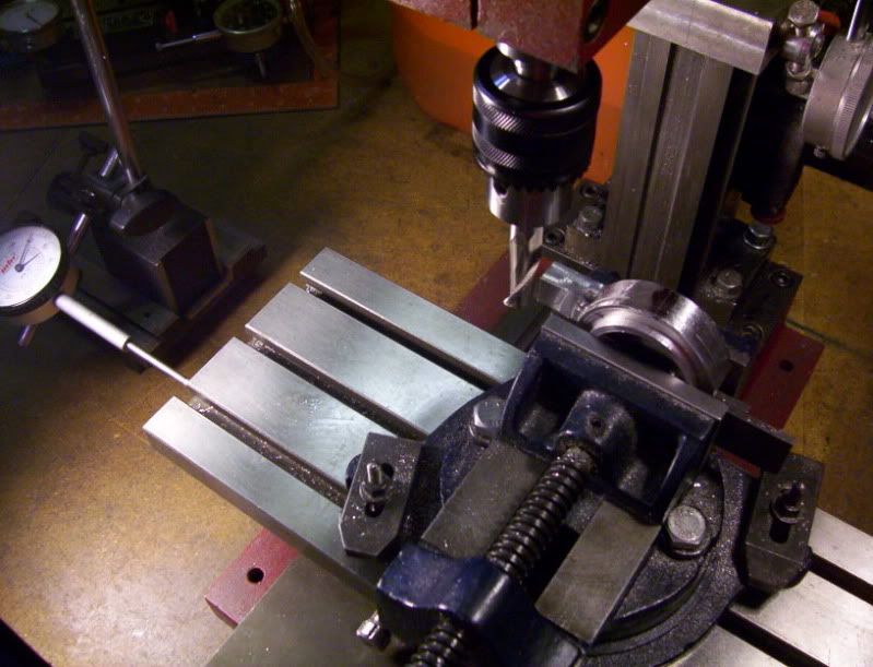
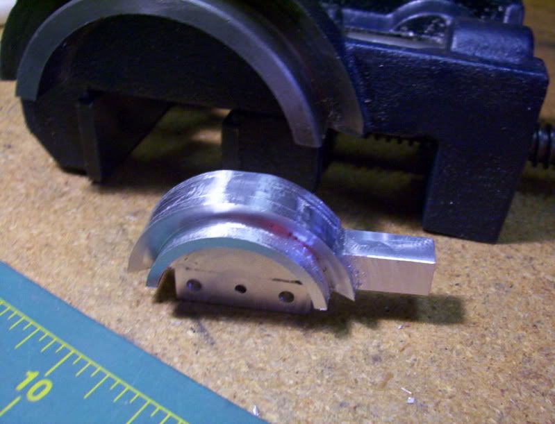
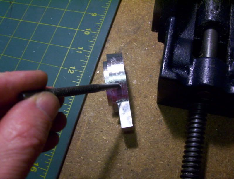
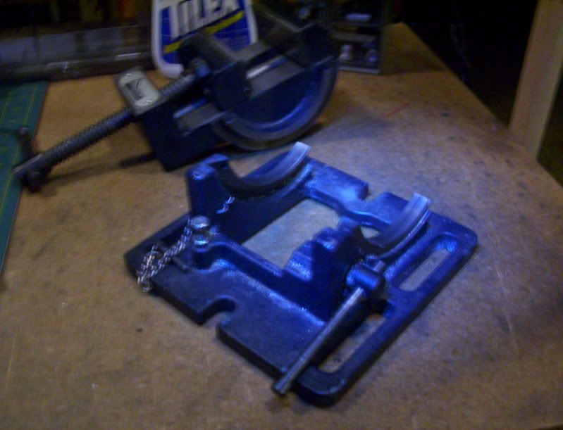
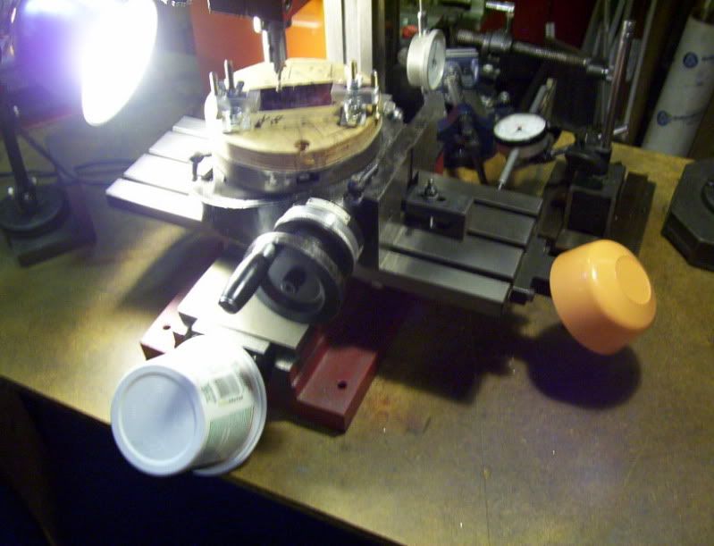
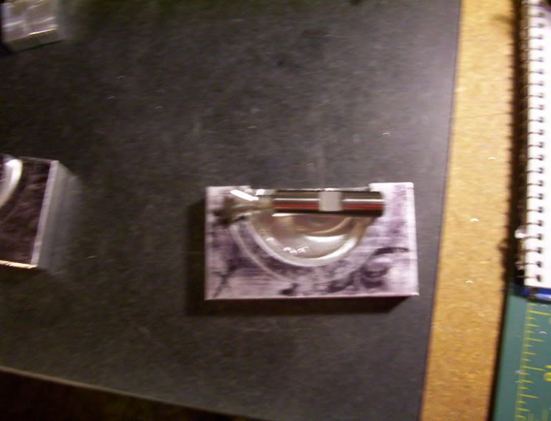
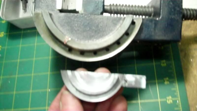
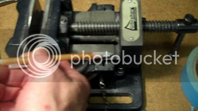
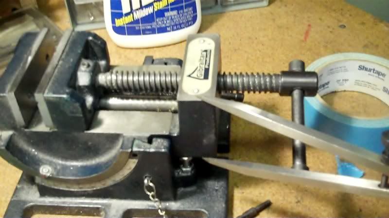
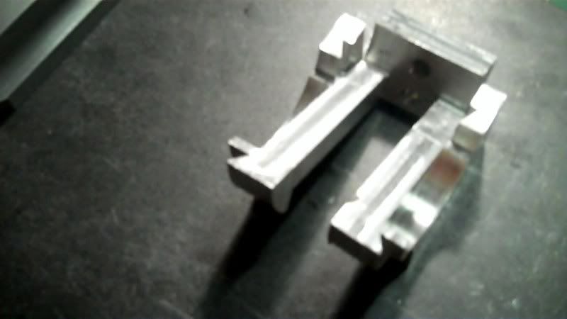
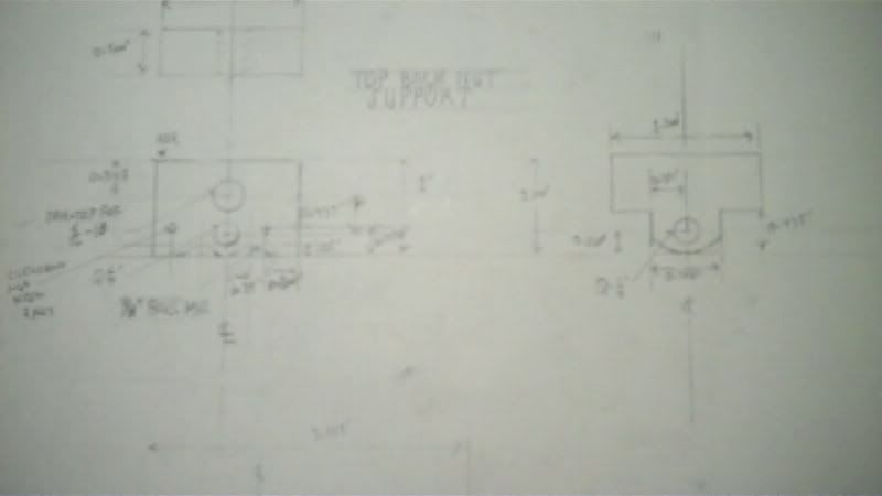
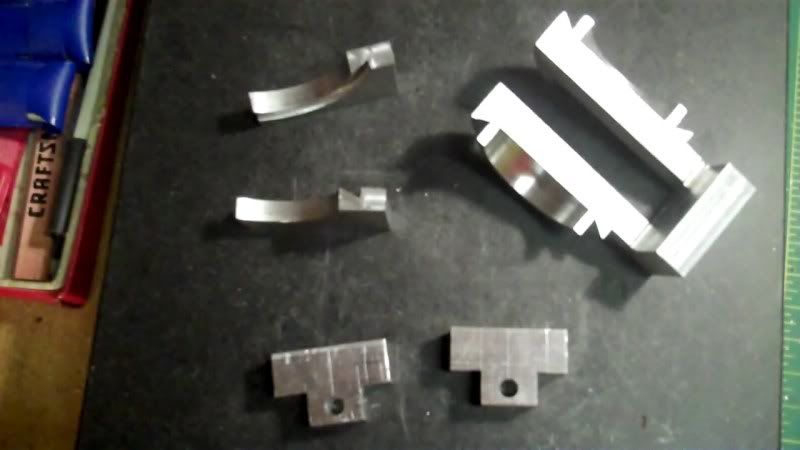
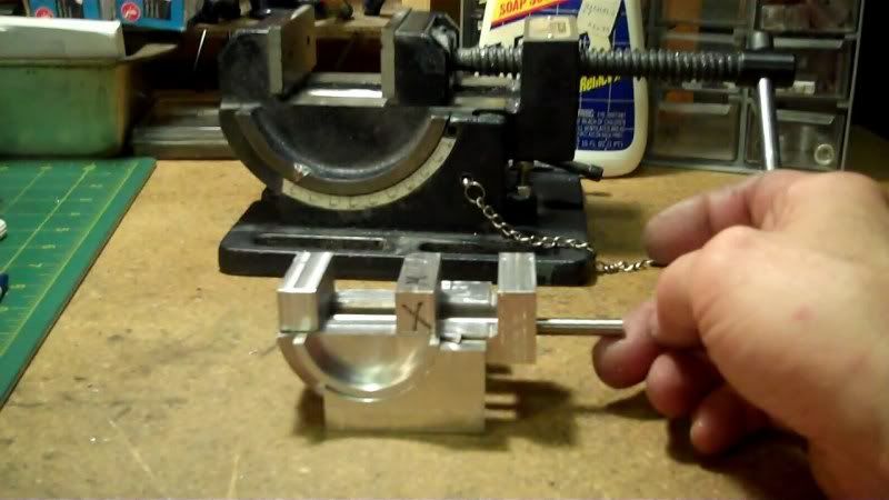
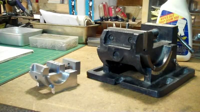
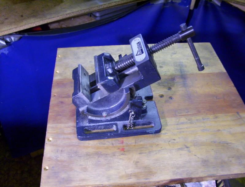
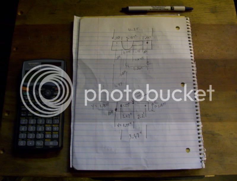
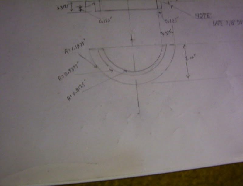
This shows the next part that needs to be made,

8-2.jpg


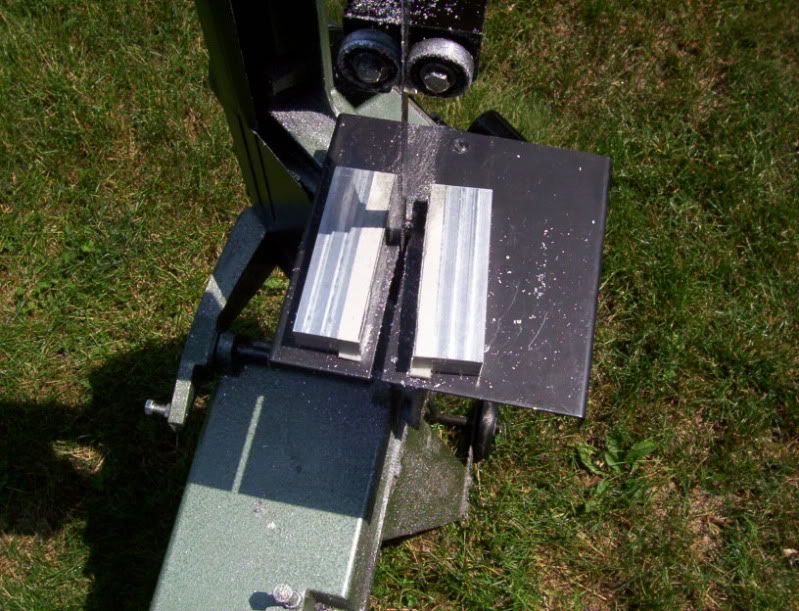
however on my project, I will attach it to the end of these workpieces, therefor to keep everything within reasonable scale, I'll need to machine these workpieces to a shorter length,

9-2.jpg


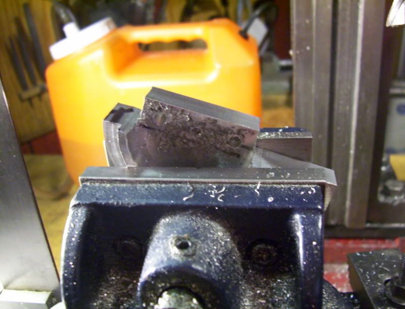
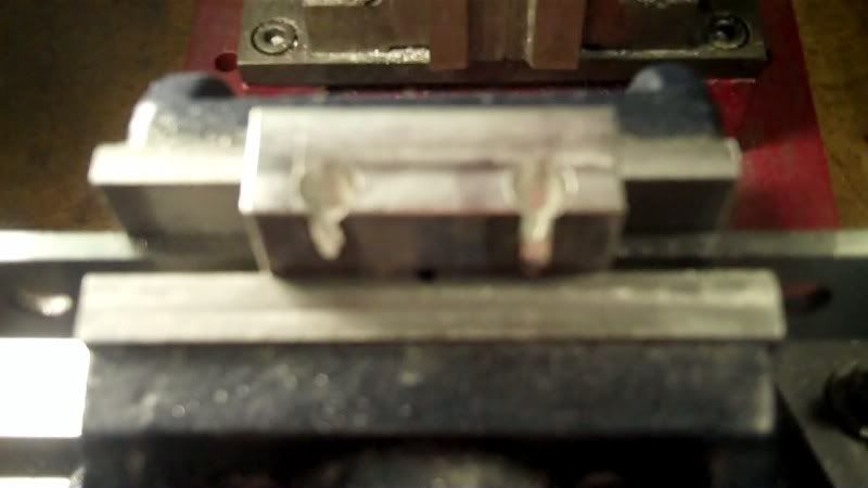
Now time to start fabricating the top front jaw of the vice.

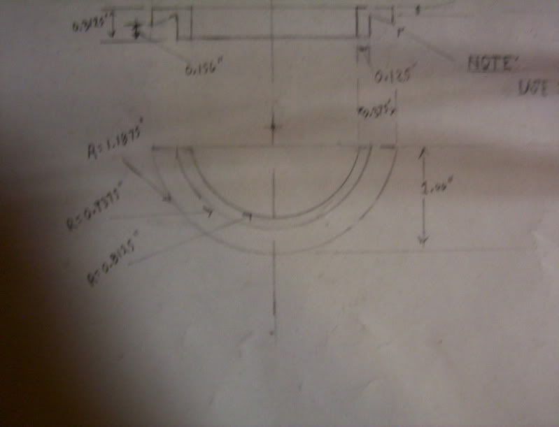
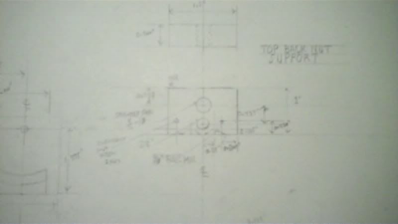
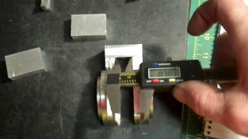
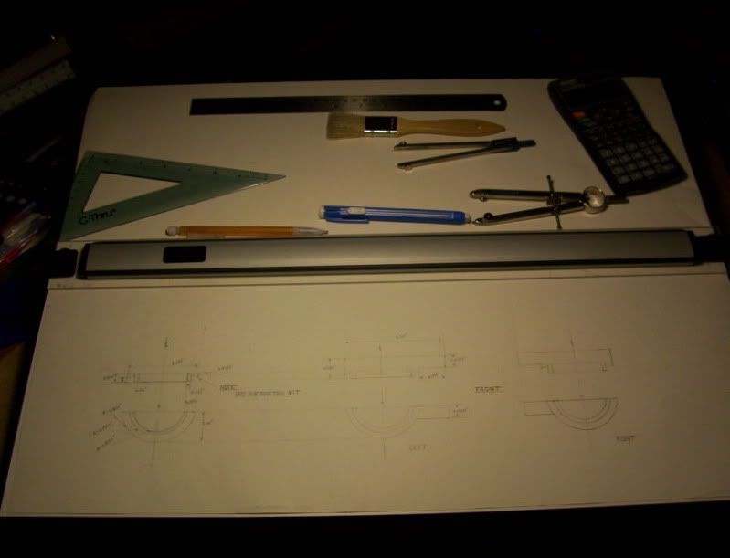
Scale some dimensions on my drawing.
10-2.jpg


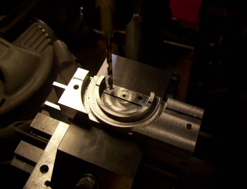
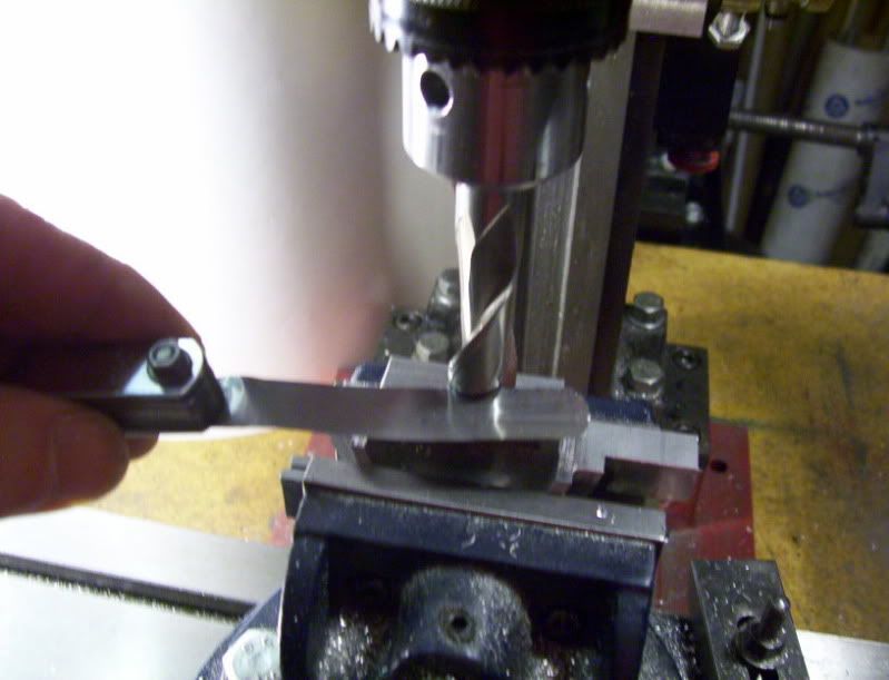
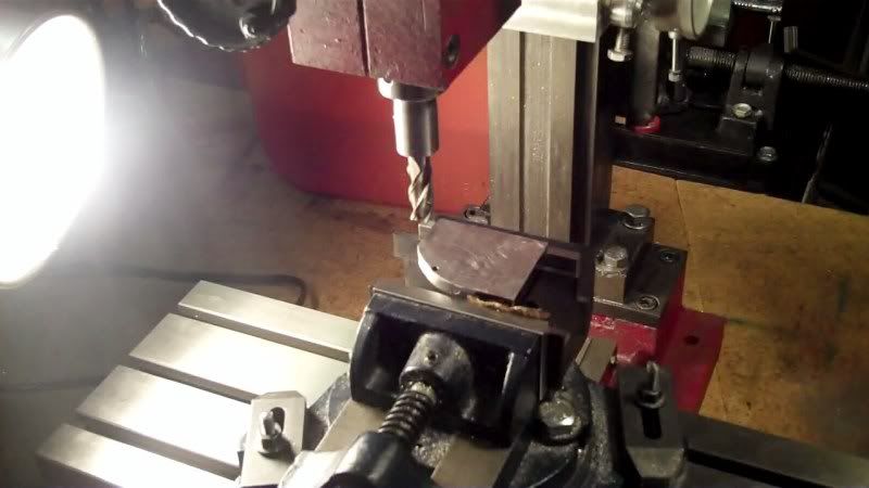
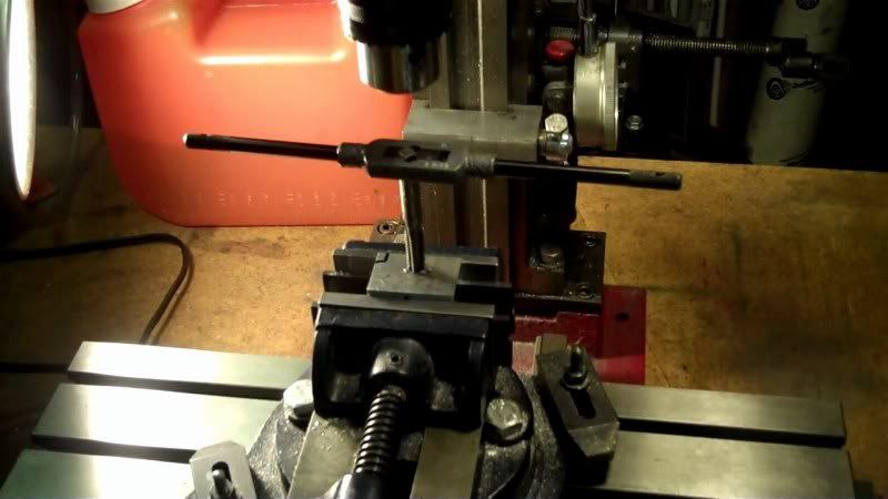
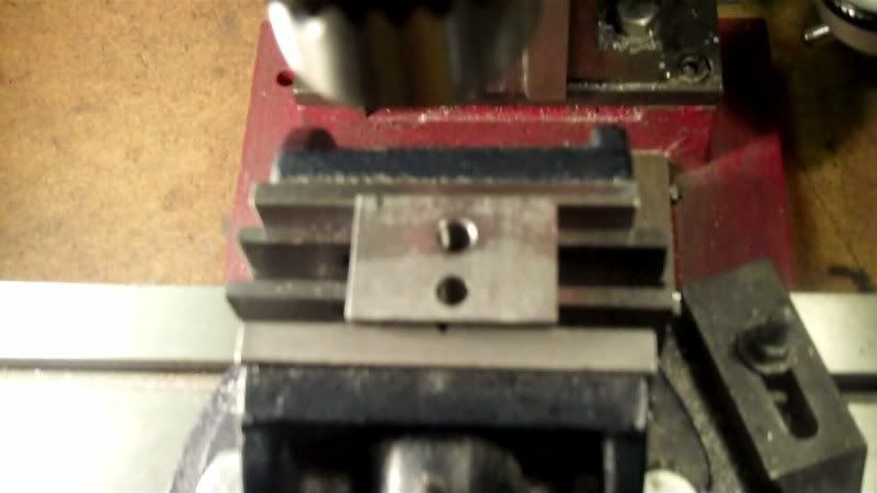
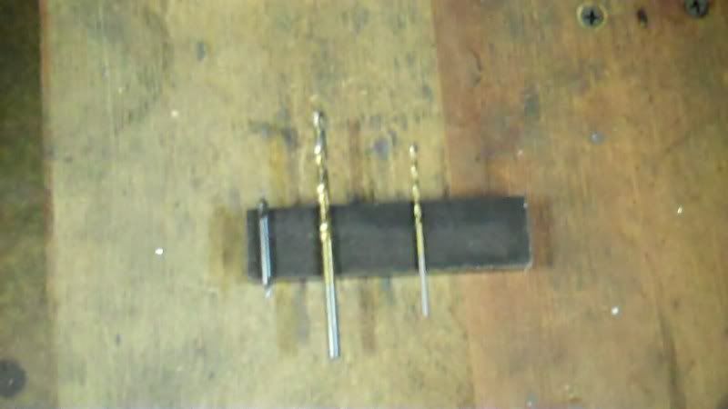
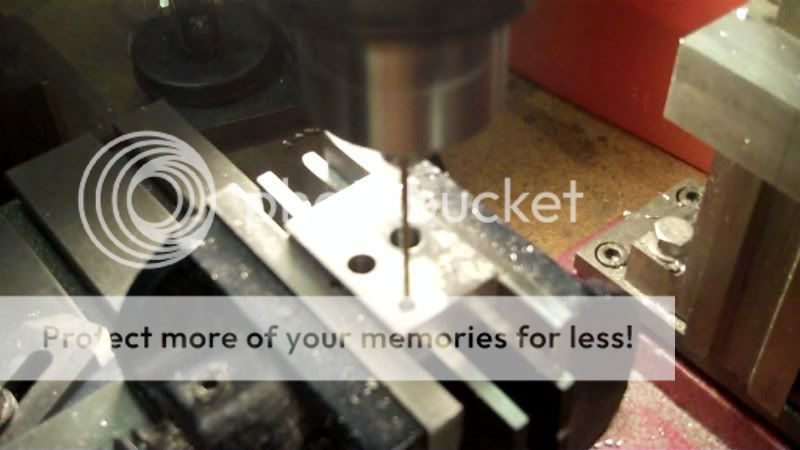
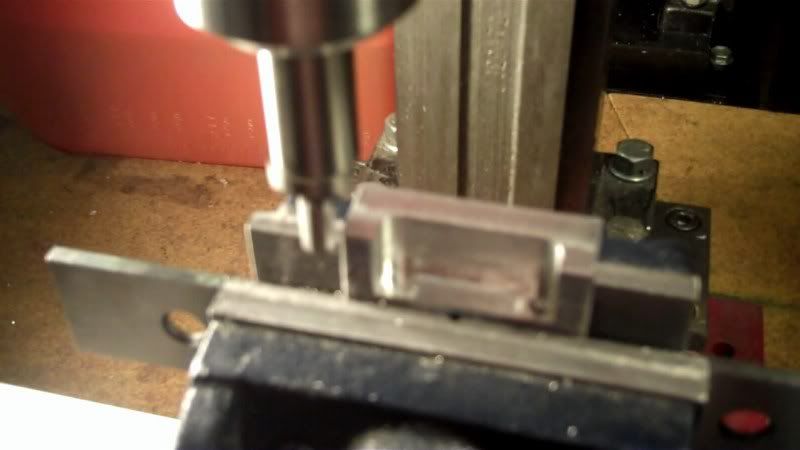
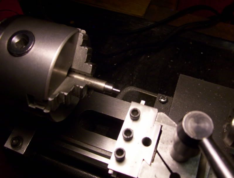
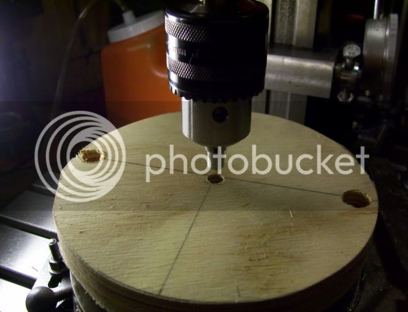
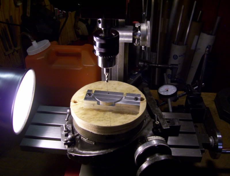
Drill and tap for the leadscrew.
11-2.jpg


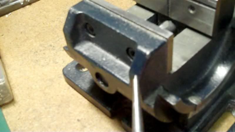
Then drill and ream for the stabilizing bar that keeps the moveable jaw from lifting too much.

12-2.jpg


13-2.jpg


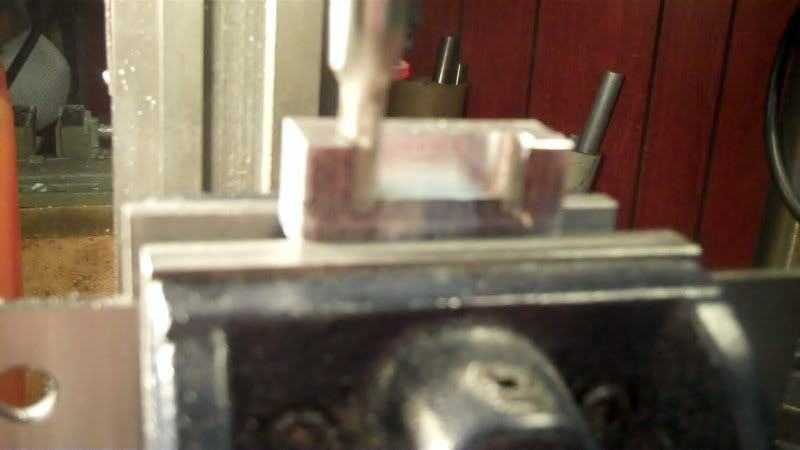
Now its time to drill for the screw holes that will attach the front jaw to the rails.
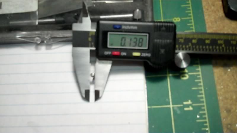
So I need to check the screw head and body size for CB. and thru holes, for 1-64 screws.

14-2.jpg


Now to locate these screw holes on the workpiece, I could reference off the center here,

15-2.jpg


However I have no way of referencing the holes on the rails because there is no center to reference from.
The reason is I have both rail sections double stick taped together, for final machining as well as hole placement, so a center reference on the front jaw workpiece has no bearing on the rails.
Therefore, I need to reference the hole locations from the outside EDGE, of each rail.

Here
16-2.jpg


and here,
17-1.jpg


Now it is a matter of referencing off of both edges of the top jaw workpiece, to drill the thru holes to attach to the rails. This way here I can keep the edges pretty much in alignment with both top jaw and bottom rails.

18-1.jpg


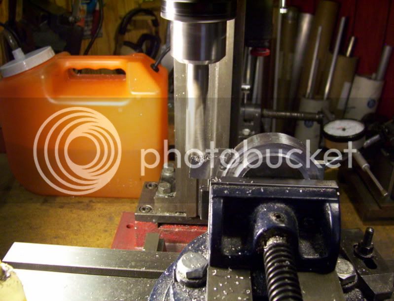
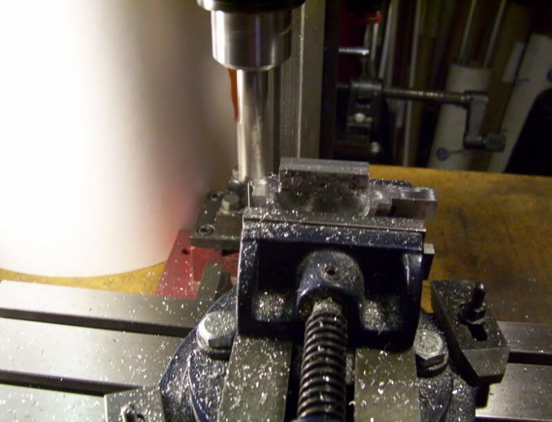
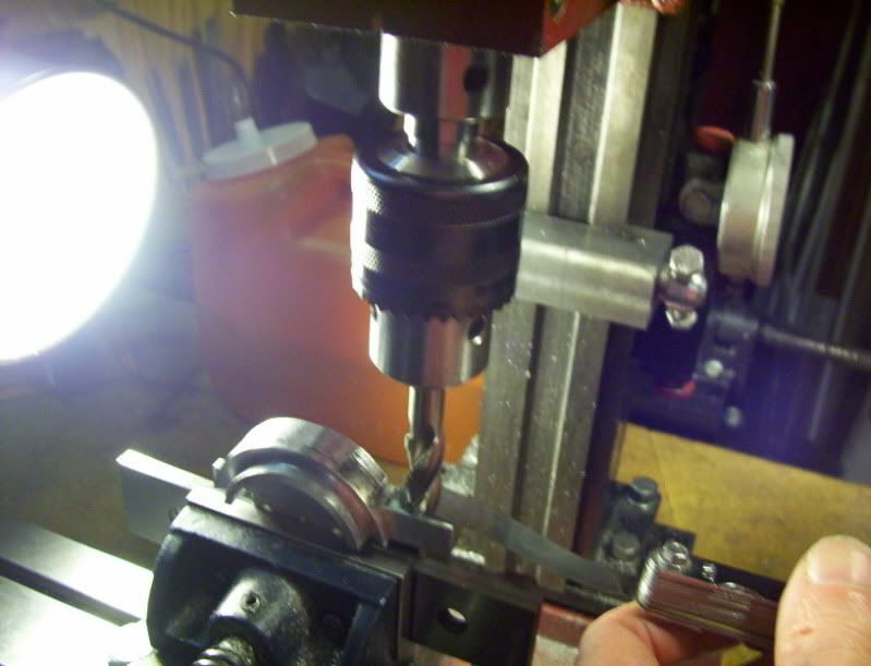
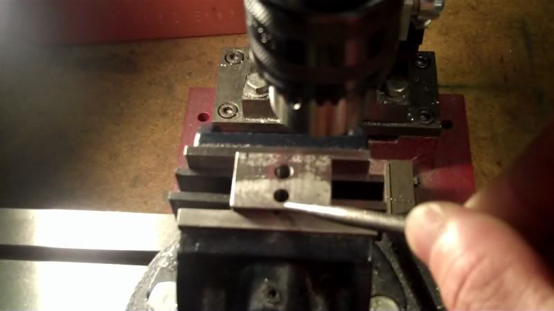
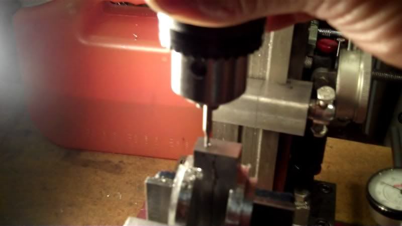
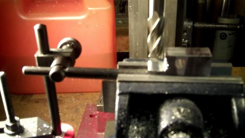
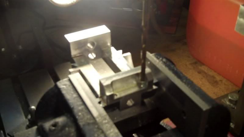
Now its time to do the counterboring and thru holes using drill bits for both.

19-1.jpg


20-1.jpg


21-1.jpg


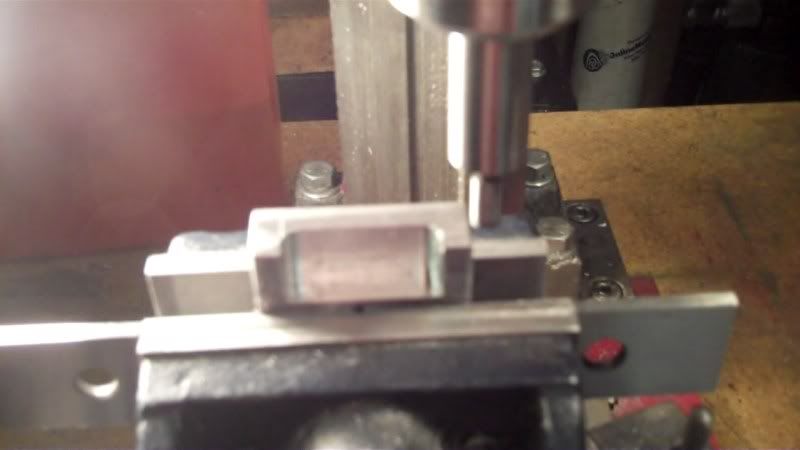
Now to do the drill and tapping operations on the rail pieces.

23-1.jpg


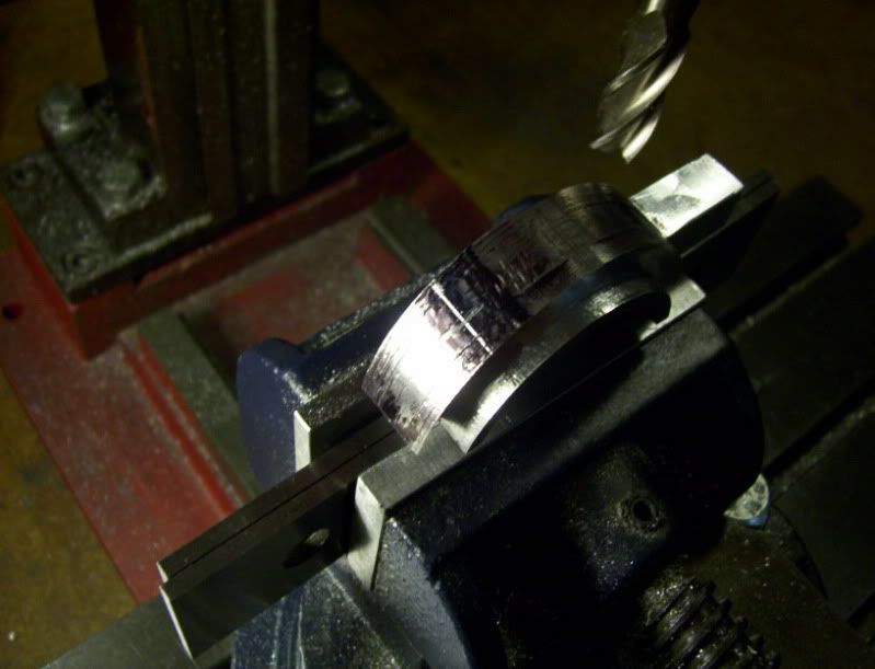
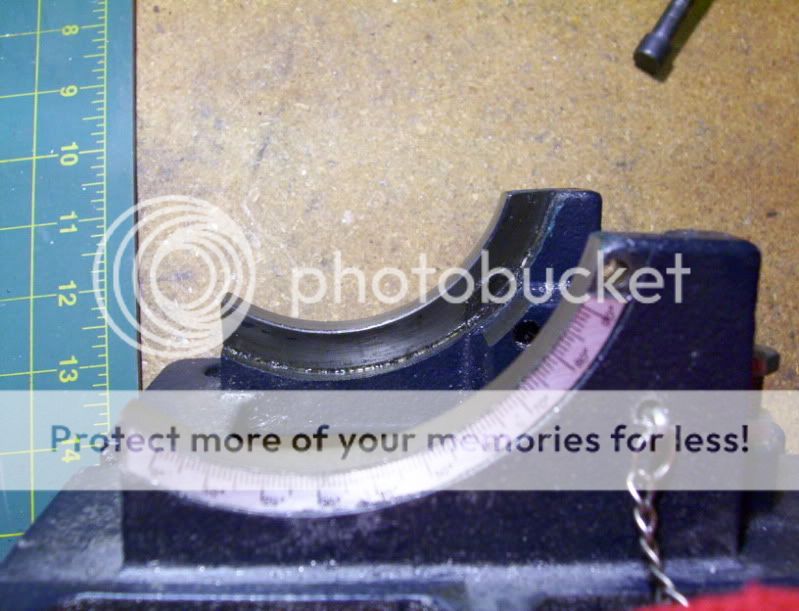
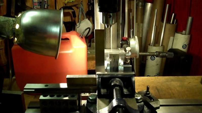
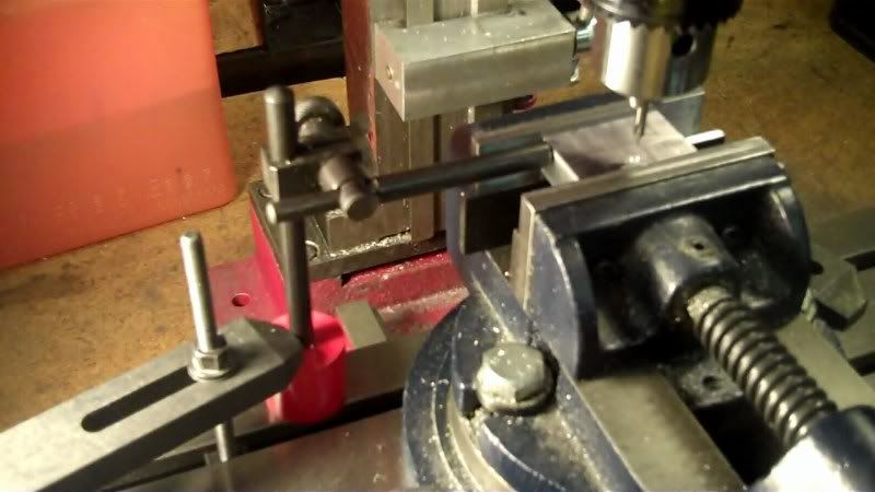
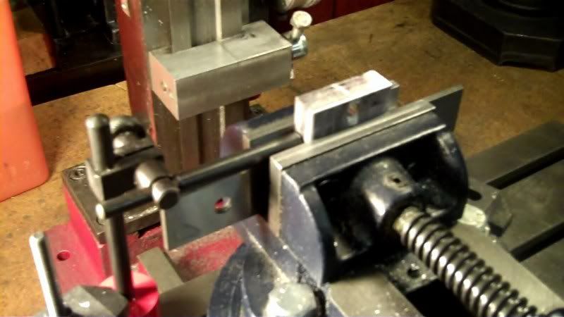
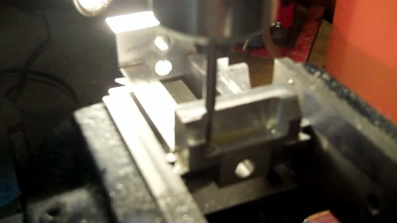
With both rail sections taped together I set it up squarely in my vice.

24-1.jpg


And now its a matter of referencing off of the outside edges to locate the holes.

25-1.jpg


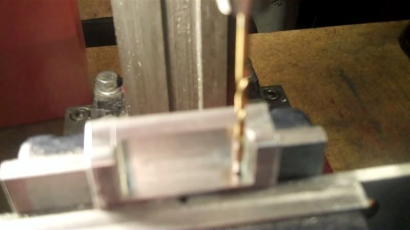
drill and tap one rail.

26-1.jpg


Locate off of the outside of the second rail

27-1.jpg


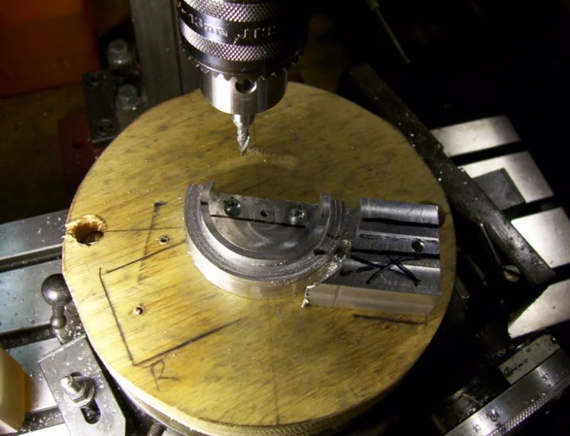
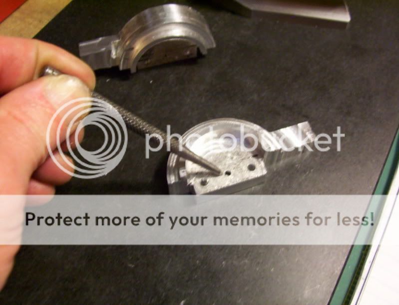
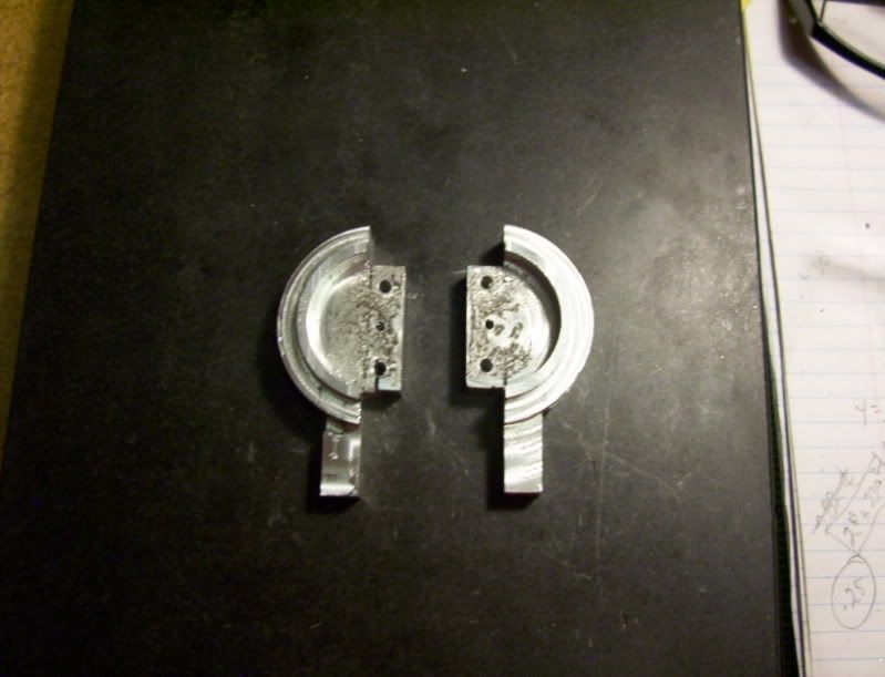
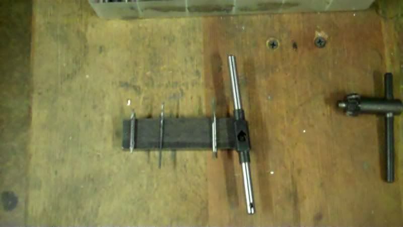
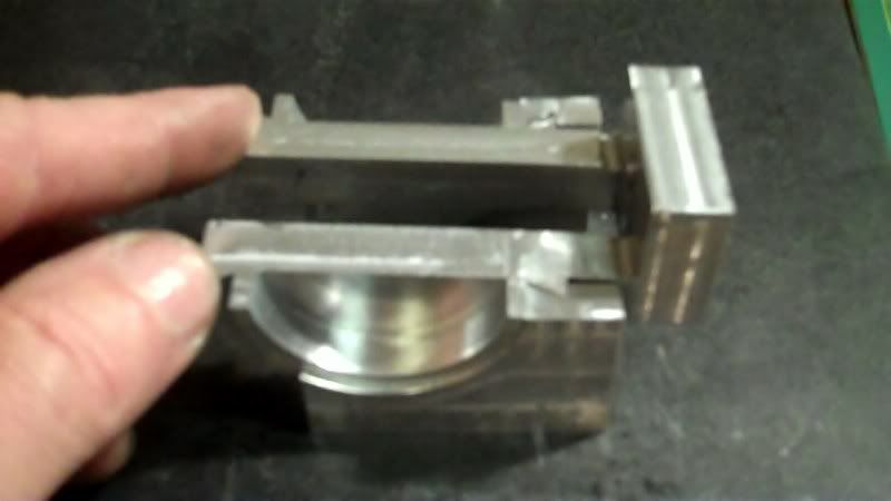
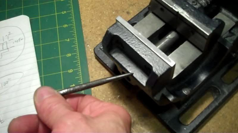
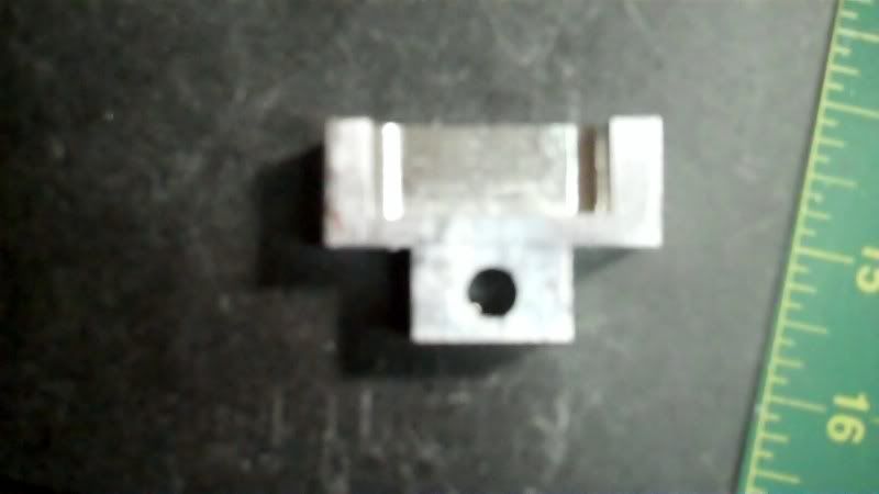
After both rails are drilled and tapped, the rail pieces can be seperated.

28-1.jpg


And temporarily screwed together to check for alignment.

29-1.jpg


30-1.jpg


31-1.jpg


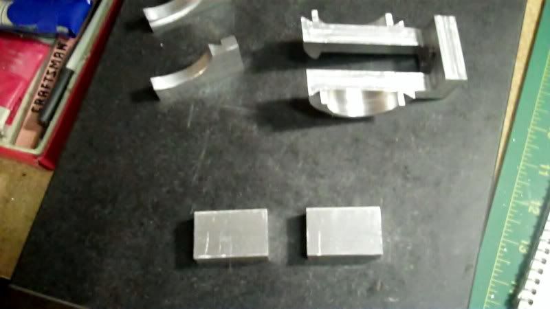
Now to work on the other top jaw, as well as the moveable jaw.
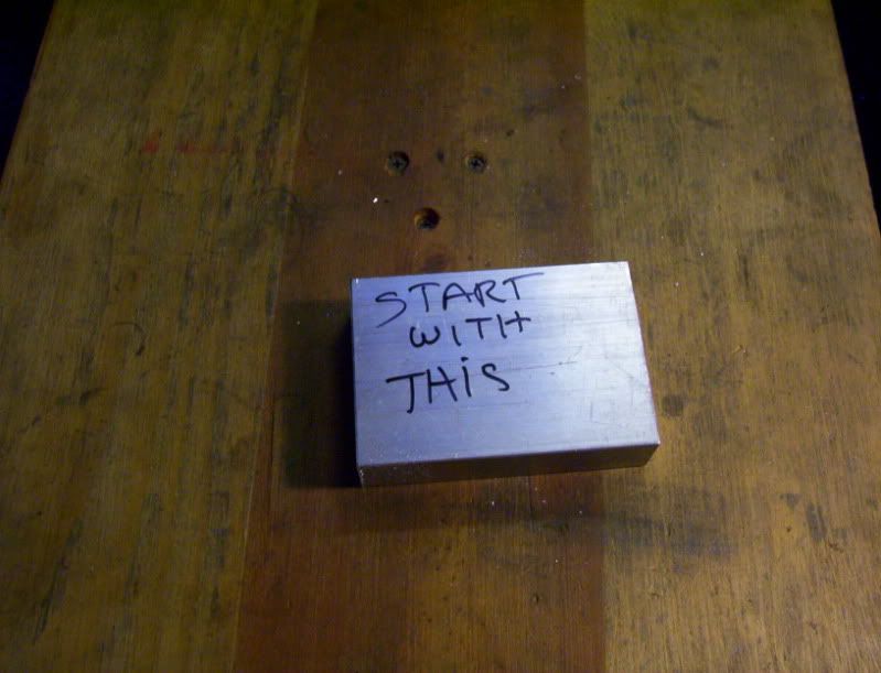
First machine the blocks to size shown at the bottom.

32-1.jpg


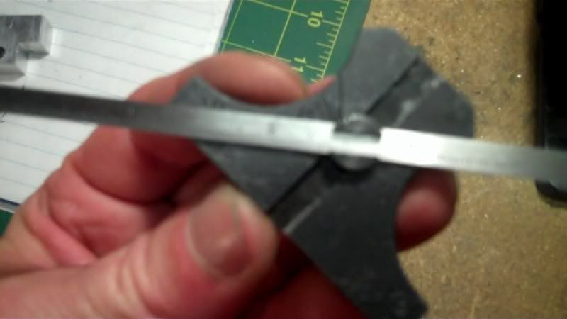
Check the distance in between the rails so the next jaw piece can be machined to fit down inside.

33-1.jpg


Now this time I will reference everything from the center of the workpieces.

34-1.jpg


After securing the needed dimensions,

35-1.jpg


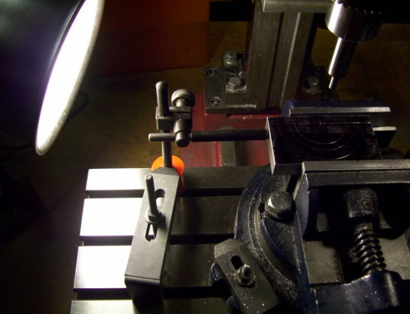
I set up the first workpiece, do all locations, and then set up a workstop for consistency between both workpieces.

36-1.jpg


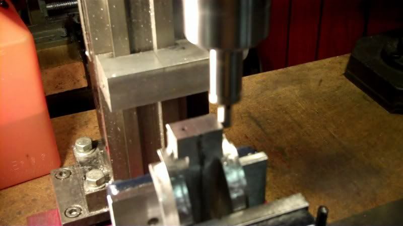
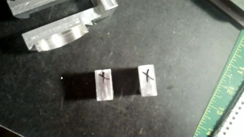
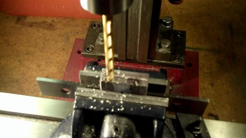
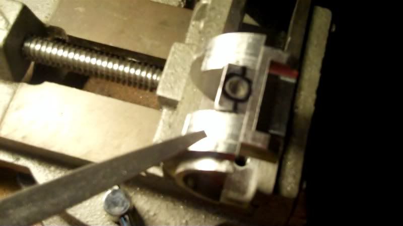
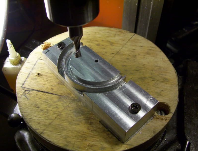
And the drilling of the stabilizer bar holes is first. This is done to both pieces.

37-1.jpg


Now making sure I have a reference edge to set against the workstop so as to keep both pieces in line with eachother, I make a witness mark on the workpieces.

38-1.jpg


And set that side to the stop

39-1.jpg


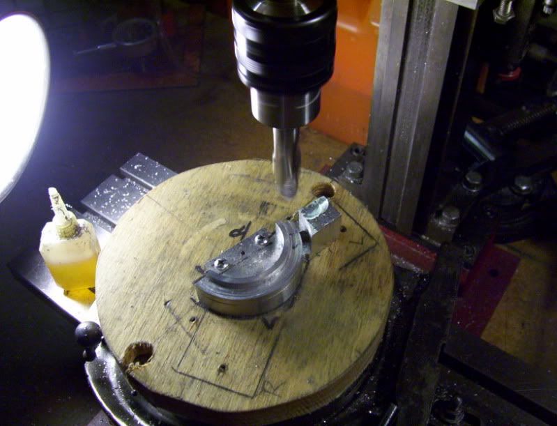
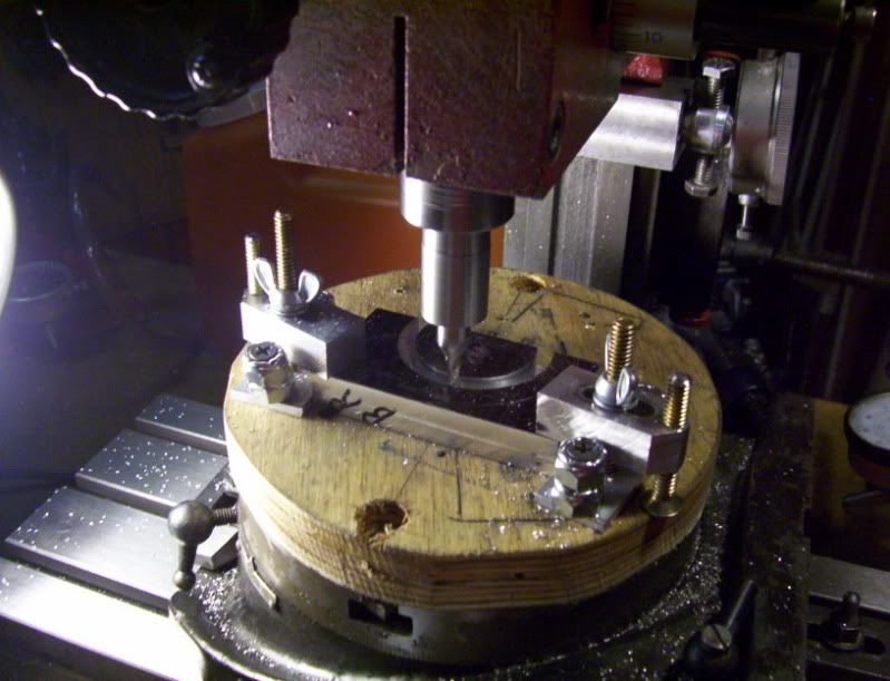
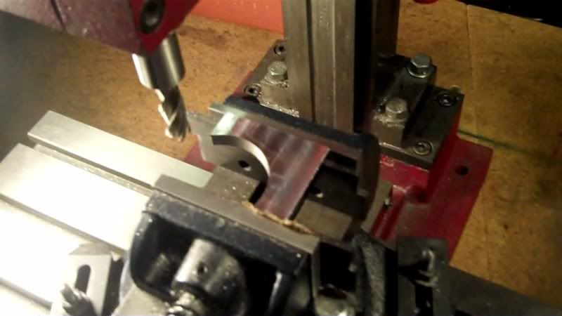
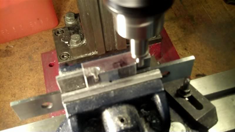
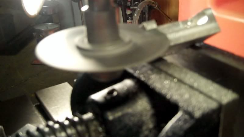
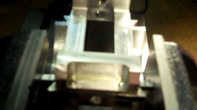
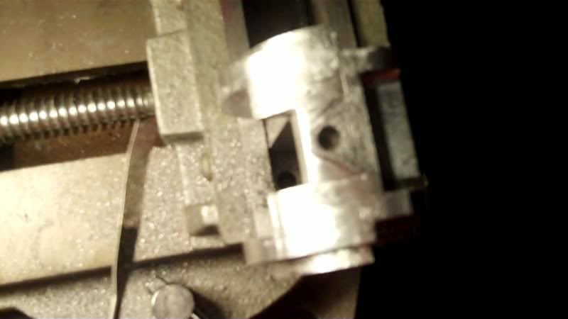
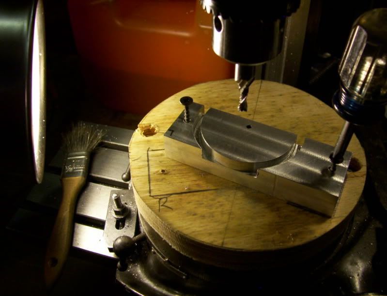
with layout marks on top I align the cutter and start cutting out all the material on each side off of center.

40-1.jpg


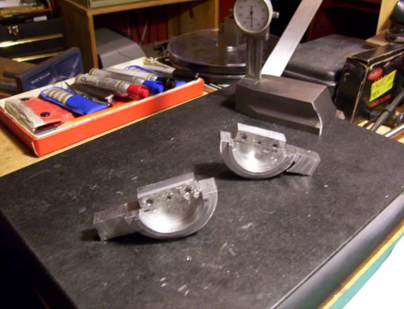
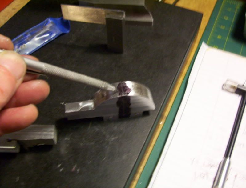
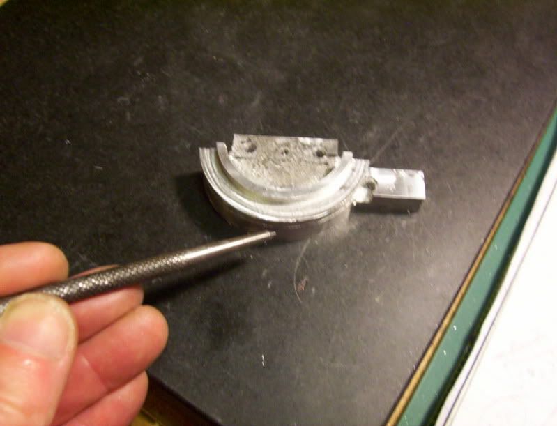
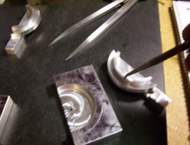
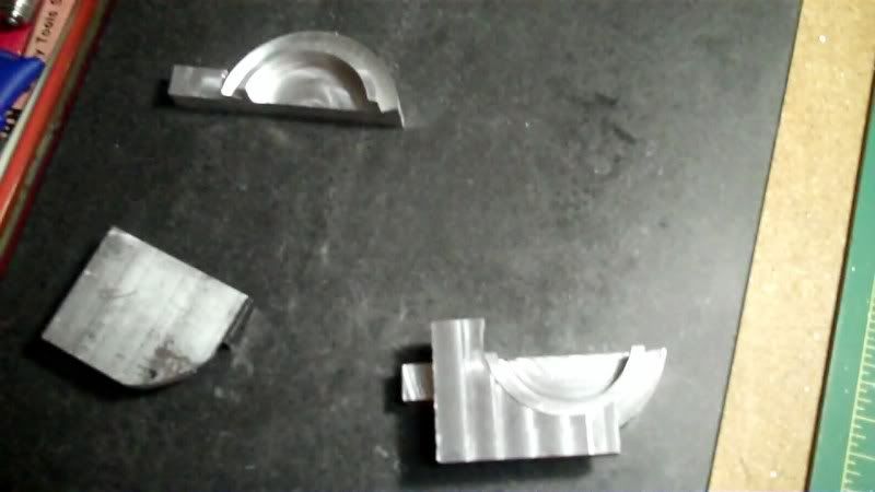
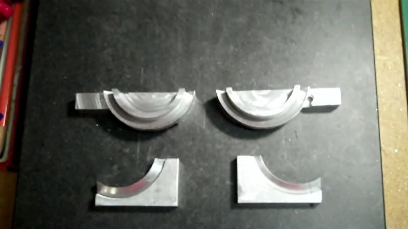
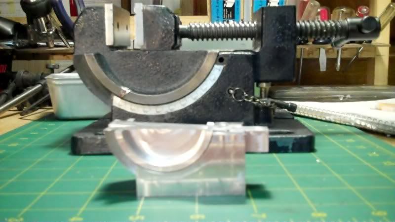
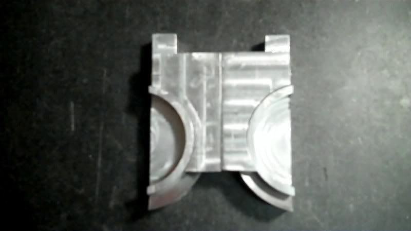
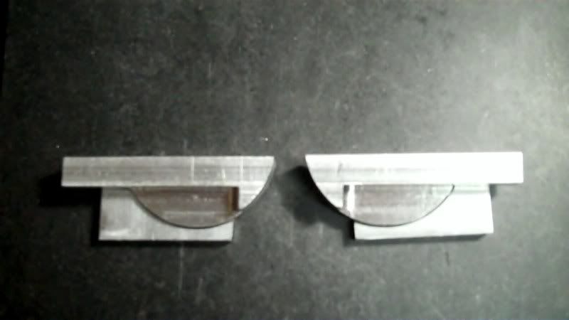
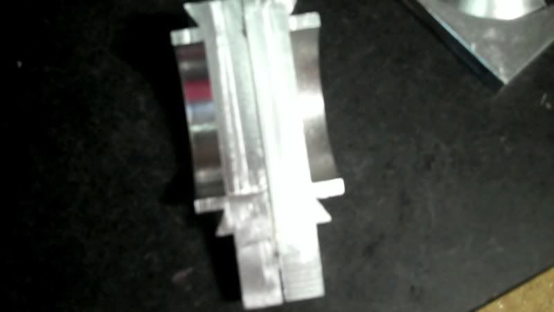
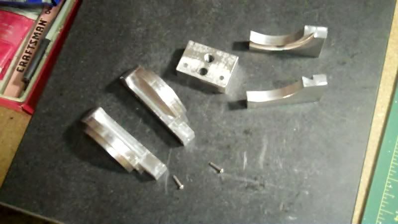
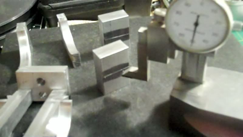
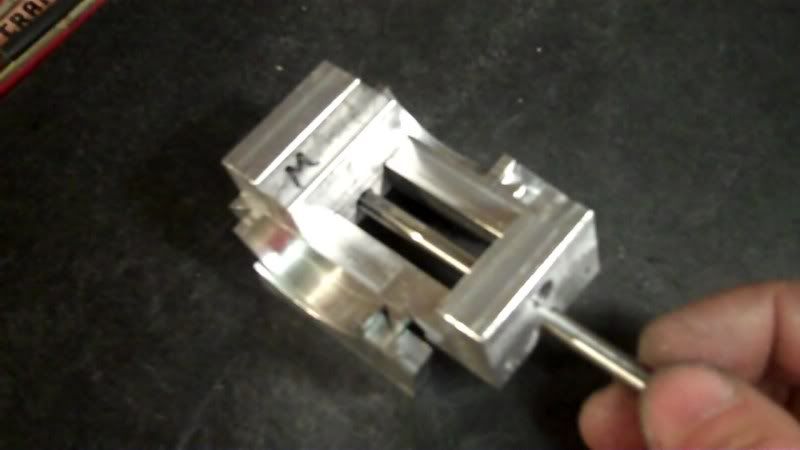
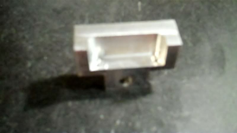
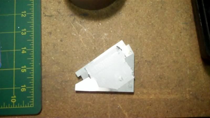
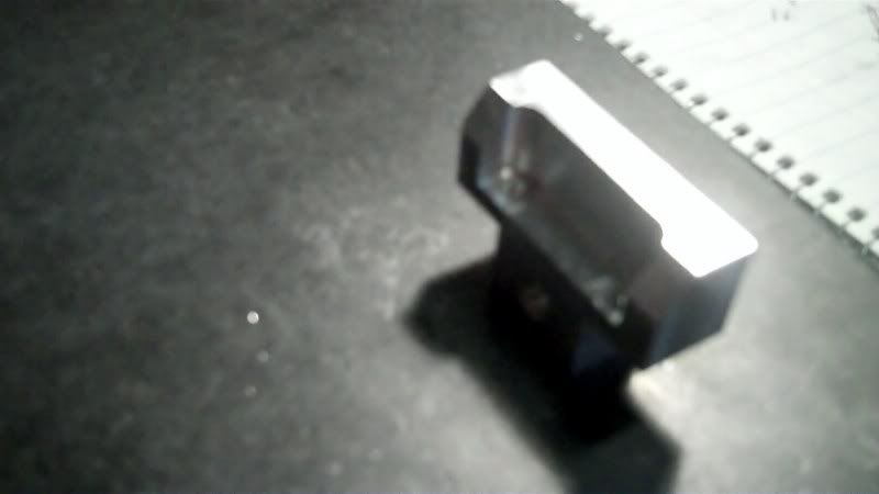
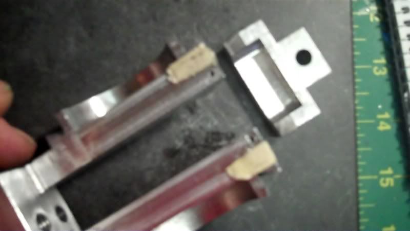
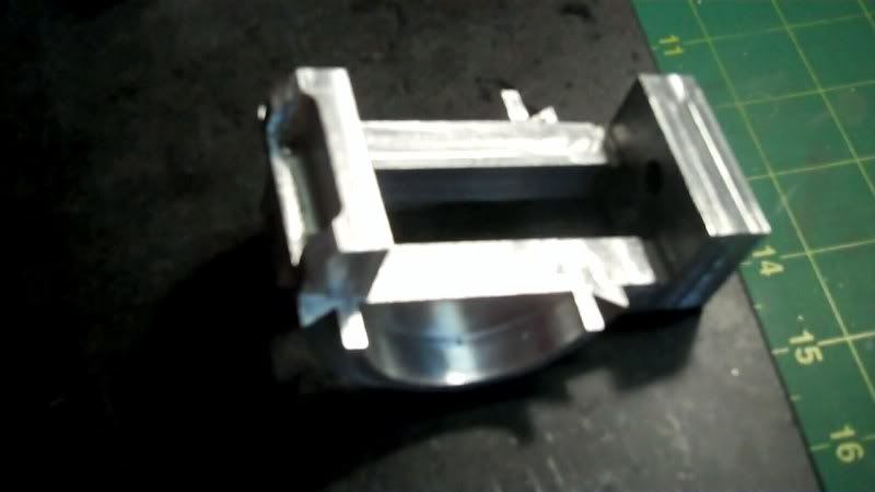
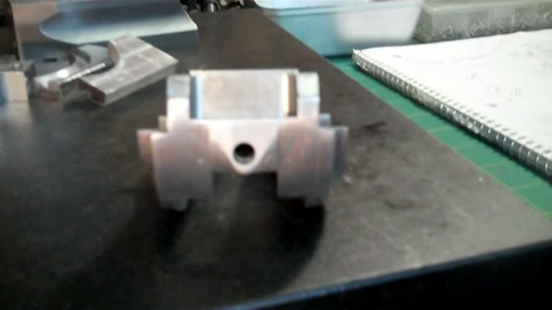
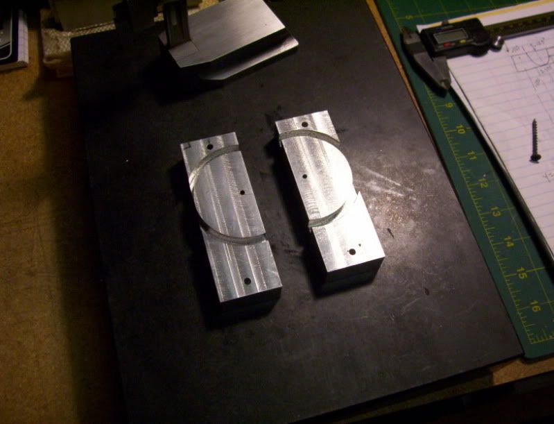
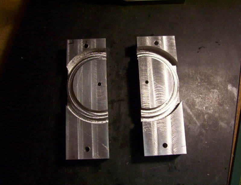
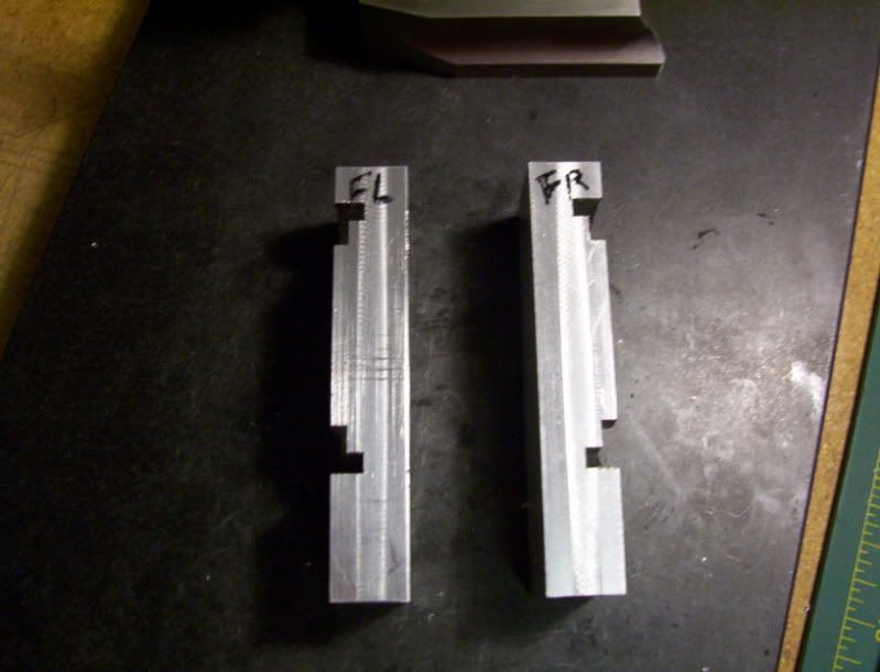
Both jaws the fixed and the moveable are completed on the first phase of the machining process,
they both need to have some profile machining done to them like the original, but for now they are fitted blanks.

41-1.jpg


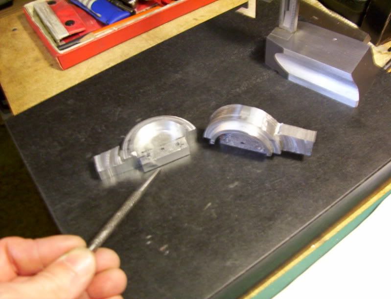
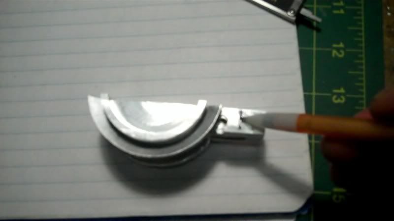
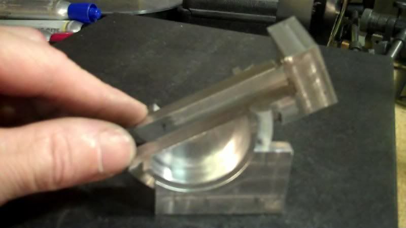
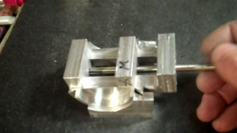
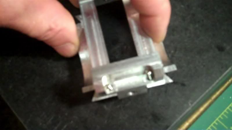
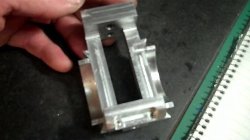
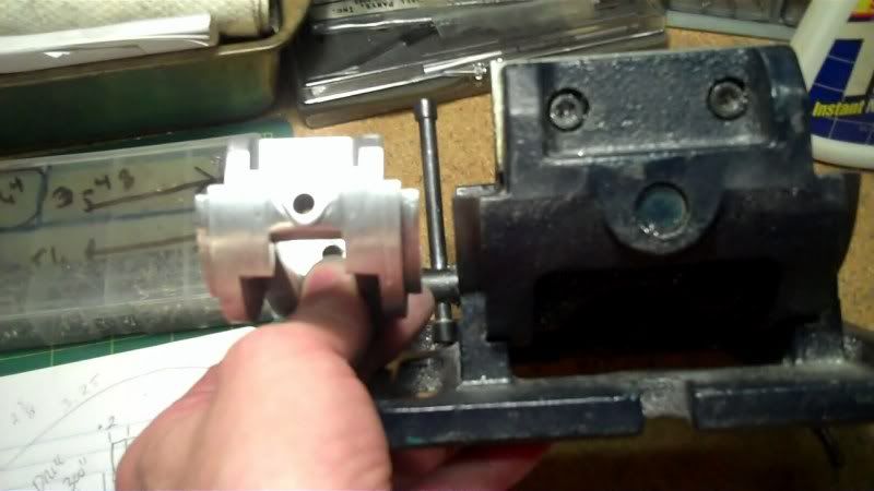
Now it's time to check for fit and alignment, I'm using the reamer I used for the blanks to use as a temporary stabilizing bar to see how everything fits and moves, in alignment with eachother.

42-1.jpg


43-1.jpg


44-1.jpg


45-1.jpg


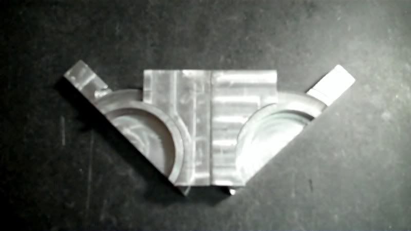
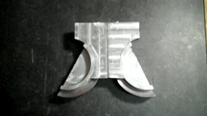
Now I need to work on the profiling of these pieces to make them look like the prototype vice.

Thanks for looking in.
Have a great day.

 
Great work so far. Loving this thread. At the end you will have a handy useable toolat the end. Keep all the pics coming, you can't have too many how it is done shots, you never know when you may need a similar set up.
Brock
 
Hi Brock,
Thankyou for the compliment.
and thanks for following along.
---------------------------------------------------------------

Hello,
Now I'm doing the profile milling and shaping on the fixed jaw.

This area here on the vice.

46-1.jpg


I Need to cut out the back side inbetween both ends.

I drilled using a 1/4" bit to make both starter and ending holes for the slot.

47-1.jpg


Referencing from the other edge to keep both edges consistent in size with eachother.

48-1.jpg


49-1.jpg


50-1.jpg


Now I need to edge find once again,

51-1.jpg


So as to locate the position of the mounting screw holes
Then using a drill for the CB. and another drill for a thru hole, for a 1-64 screw.

52-1.jpg


53-1.jpg


And again locate the other edge, using the edges as reference points on this workpiece.

54-1.jpg


55-1.jpg


56-1.jpg


Now I need to make this angle cut located here, on the prototype vice.

57-1.jpg


I measured the angle to be around 37*. with a protractor.

58-2.jpg


59-1.jpg


Then using 3 of my angle blocks to make up 37*, I then duct taped them together on one side to make it easier to handle the bulk,

60-1.jpg


when setting them up in the vice, with the workpiece.

61-1.jpg


I chose to use a slitting saw to cut the angles on the workpiece.

62-1.jpg


63-1.jpg


and the angles cutted.

64-1.jpg


Now I need to drill and tap for the mounting screws into the rail assembly.

65-1.jpg


There are several ways of doing this, I chose to go with a direct transfer, by
using double stick tape, on the workpiece with the holes predrilled

66-1.jpg


and sticking this workpiece directly in place on the rail assembly.

67-1.jpg


Then taking this whole assembly to the mill vice, and after squaring it up

68.jpg


I then took the CB drill I used earlier, and used this bit as a line up pin, to align the spindle in the center of the mounting holes.

69.jpg


Then from there drilled

70.jpg


and tapped for 1-64 screw.

71.jpg


Then put a temporary 1-64 screw in that hole,

72.jpg


While a line up for drilling and tapping the next hole.

73.jpg


Then removing the assembly from the vice I can seperate the parts

74.jpg


and permanently screw the pieces back together.

75.jpg


76.jpg


77.jpg


Now it's time to do some profile filing.

78.jpg


79.jpg


To make it look close to the original prototype vice.

80.jpg


81.jpg


82.jpg


Next I'll need to work on the moveable jaw, and add the soft jaws to both these, then the base work.

Thanks for watching.
 

Latest posts

Back
Top