
You are using an out of date browser. It may not display this or other websites correctly.
You should upgrade or use an alternative browser.
You should upgrade or use an alternative browser.
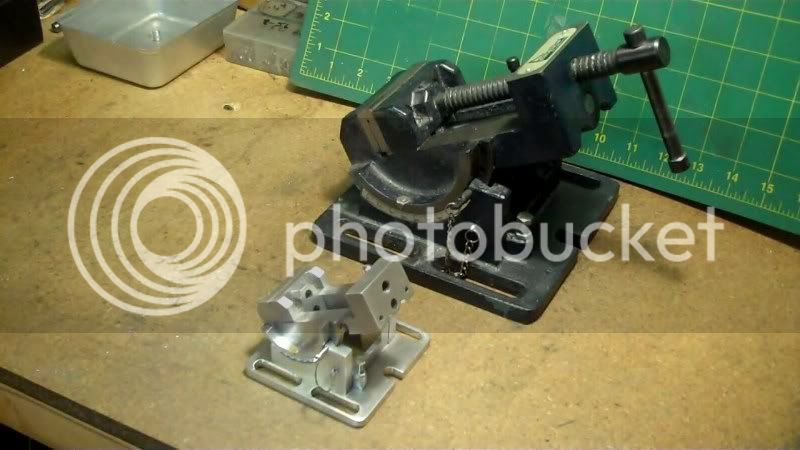
1/2: scale model of my angle vise build
- Thread starter hobby
- Start date


Help Support Home Model Engine Machinist Forum:
This site may earn a commission from merchant affiliate
links, including eBay, Amazon, and others.
- Joined
- Dec 5, 2009
- Messages
- 510
- Reaction score
- 47
Kel,
Thanks for the compliment, and thanks for looking in.
------------------------------------
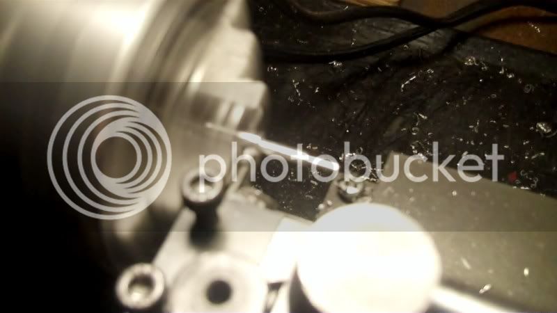
I put about an hour in this evening, to get the locking mechanism built.
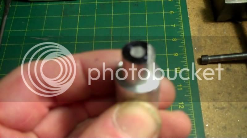
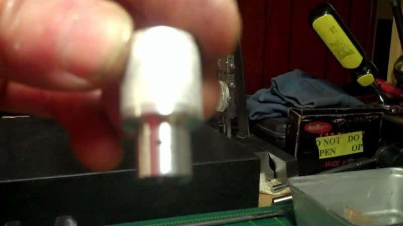
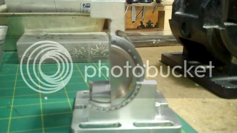
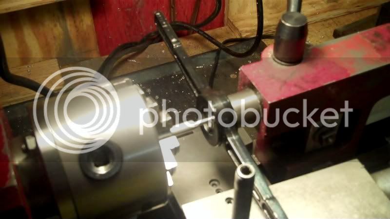
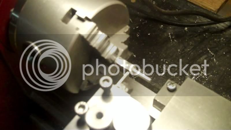
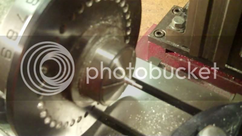
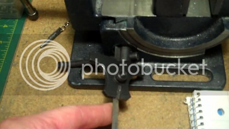
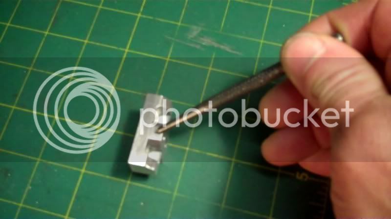
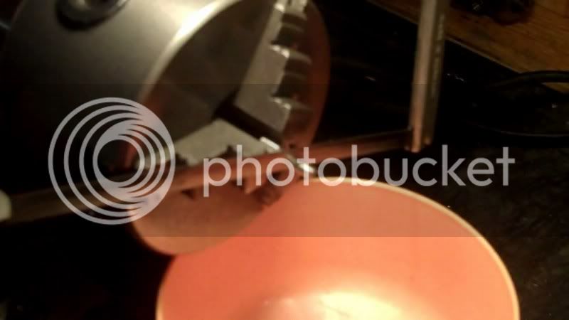
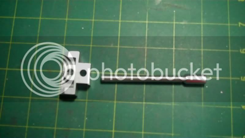
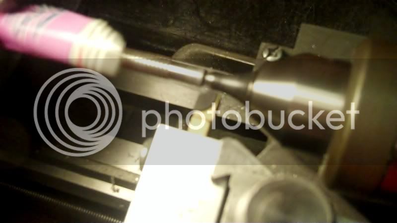
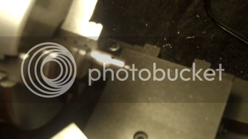
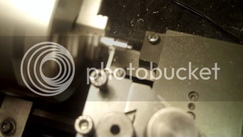
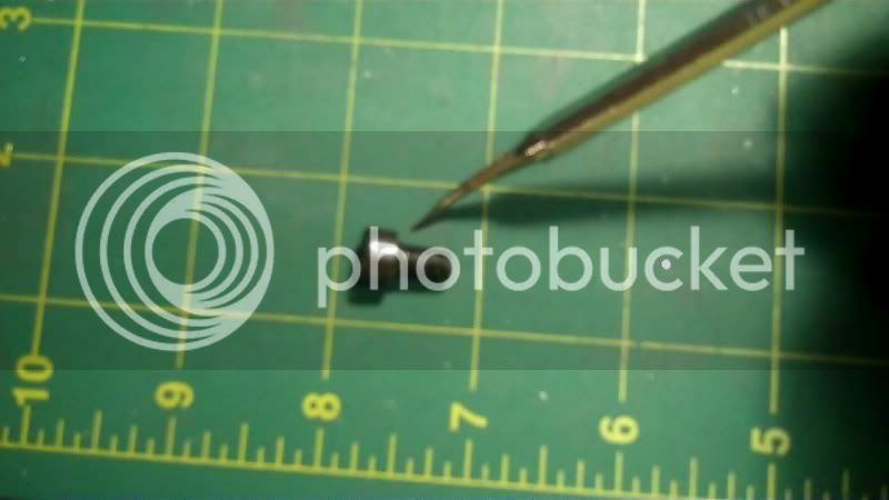
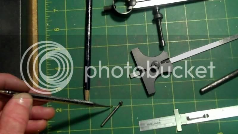
I machined a piece of aluminum rod, down to 1/2" dia. and drilled a thru hole to fit a body diameter screw of 10-32..
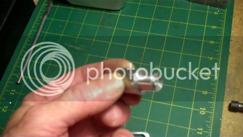
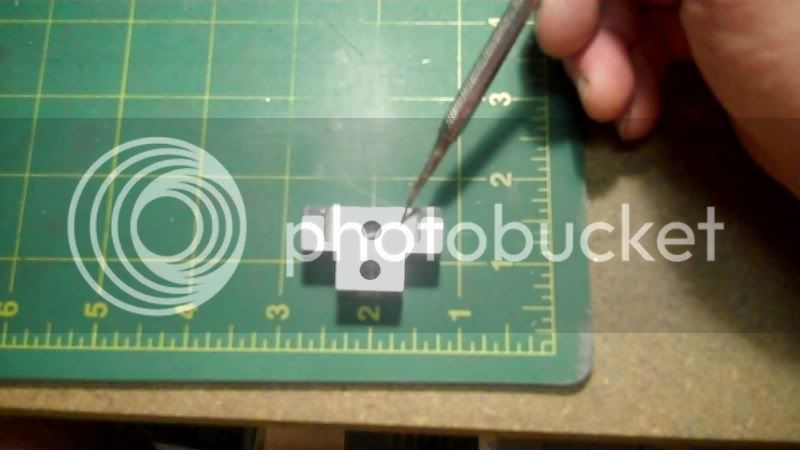
The only way I could think of to mark the location of the dovetail cut was to put this blank into it's hole, and mark whwere it sticks thru on the inside like this.
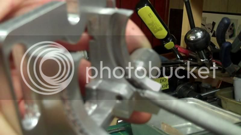
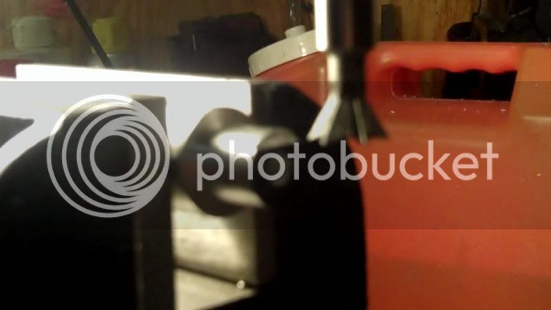
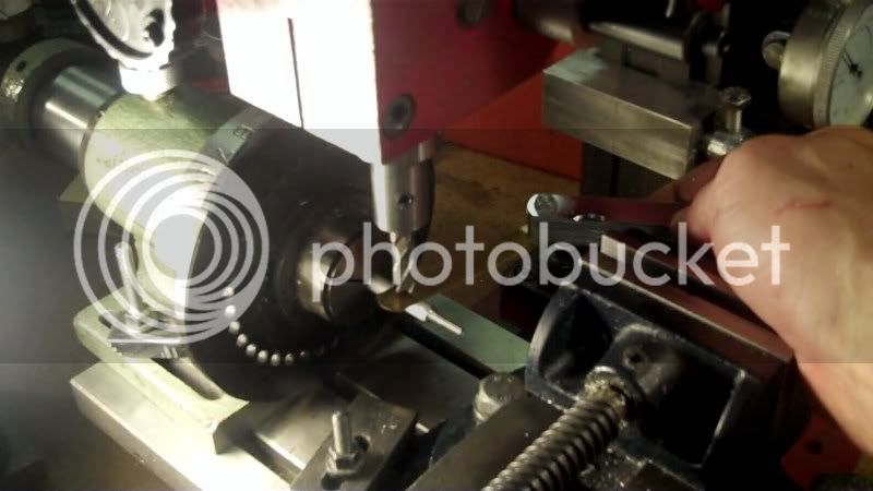
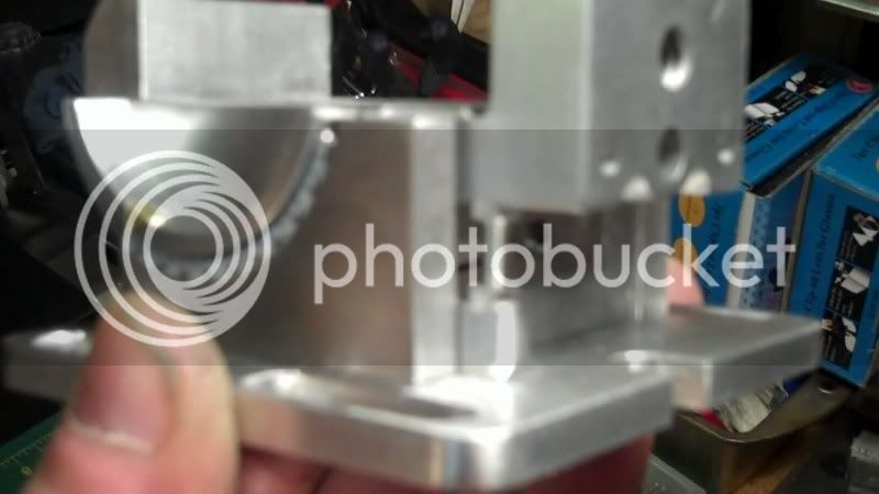
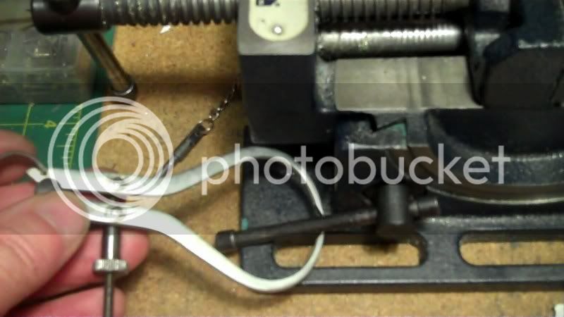
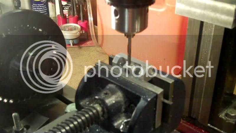
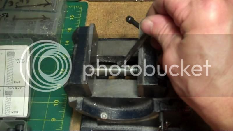
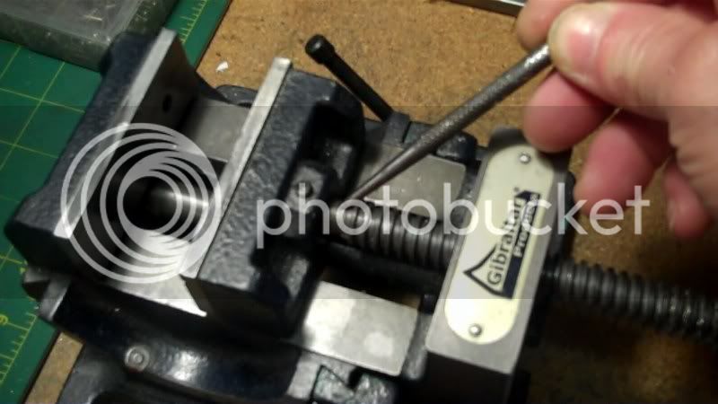
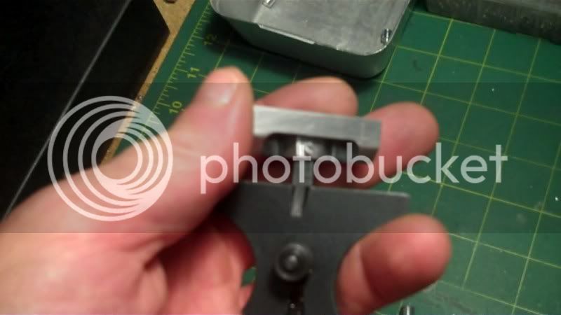
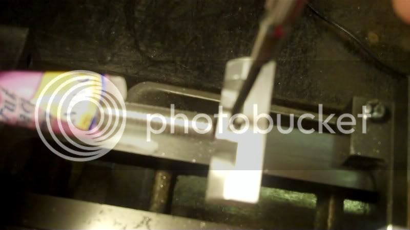
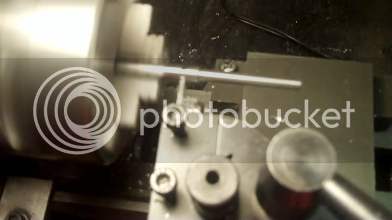
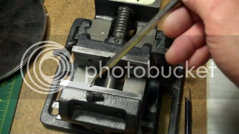
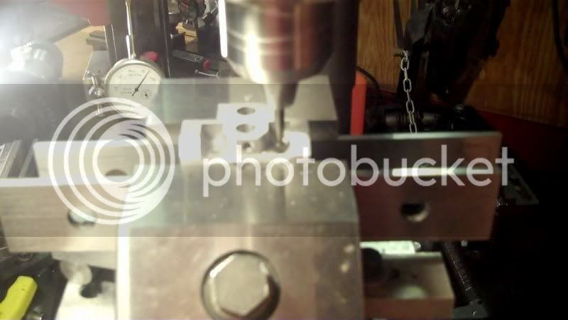
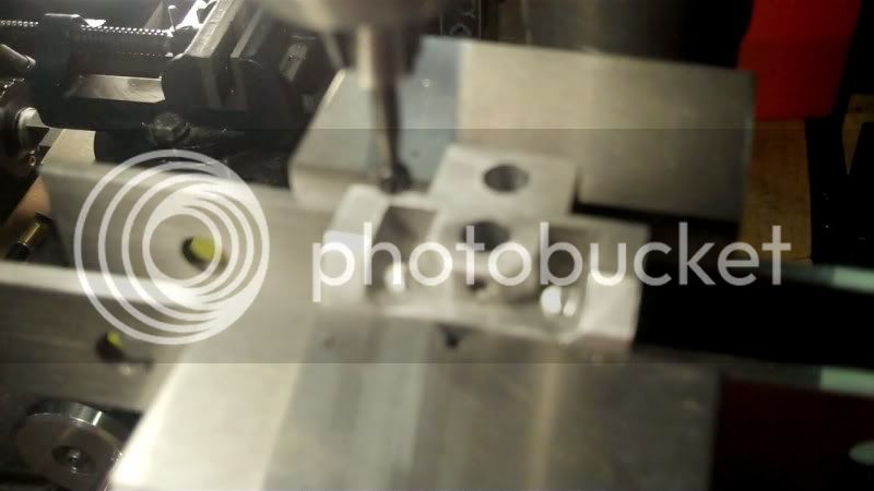
Then line it up in my milling vice
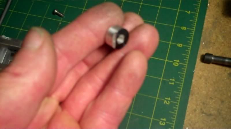
and cut the dovetail into it.
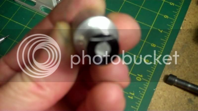
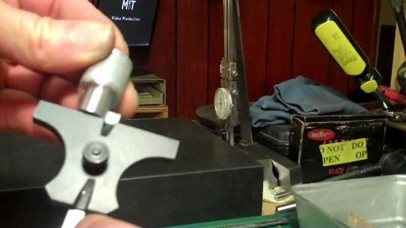
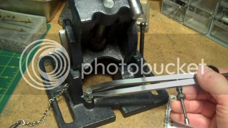
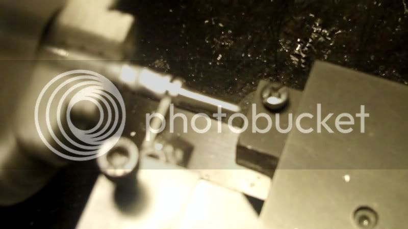
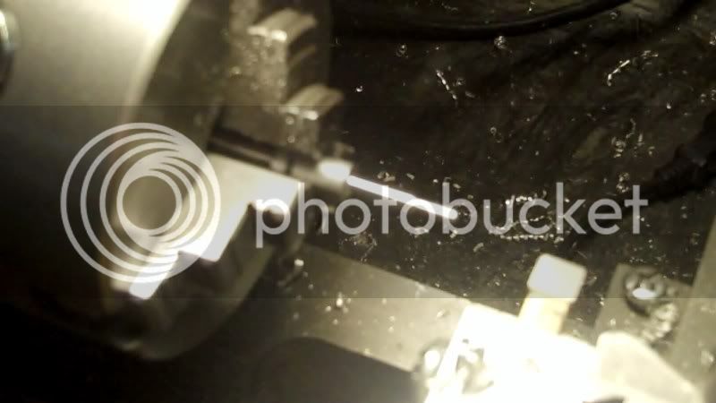
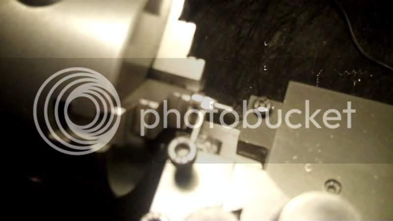
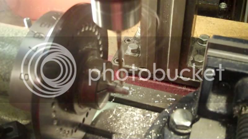
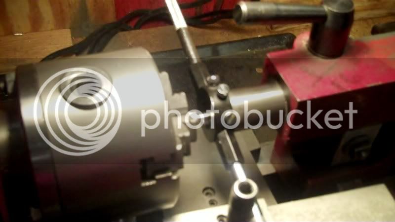
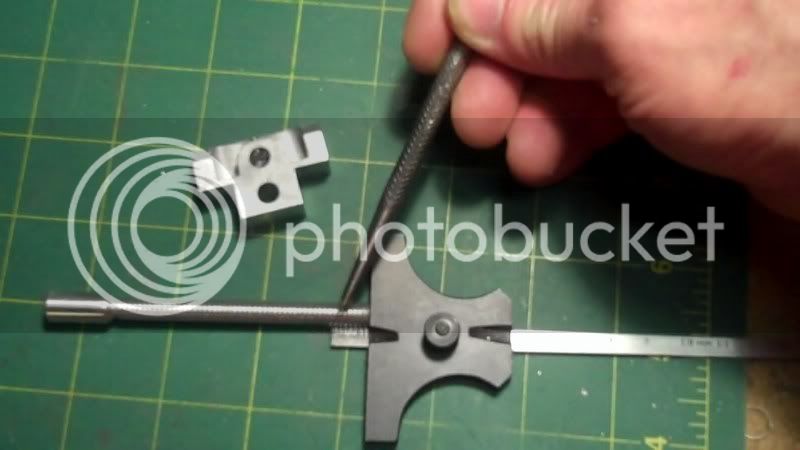
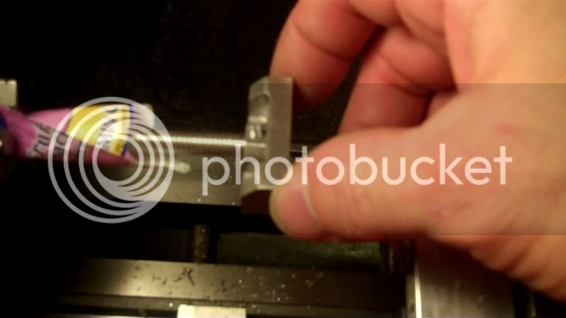
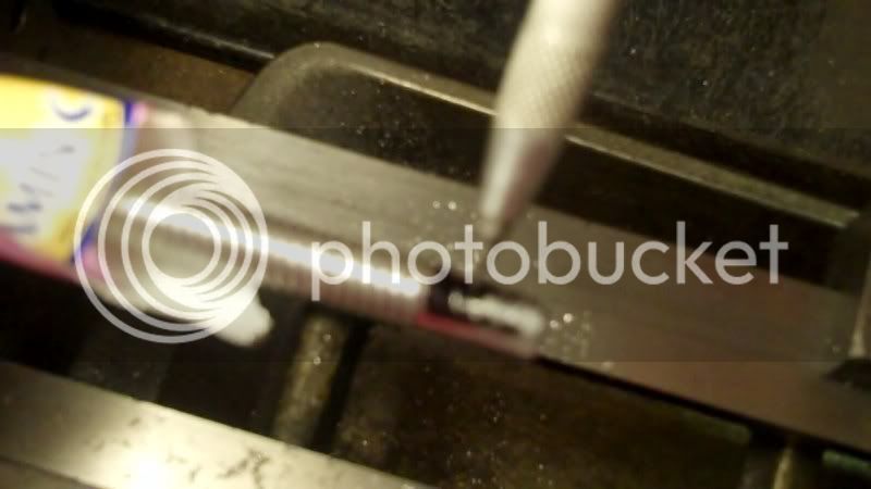
Now to take a depth measurement
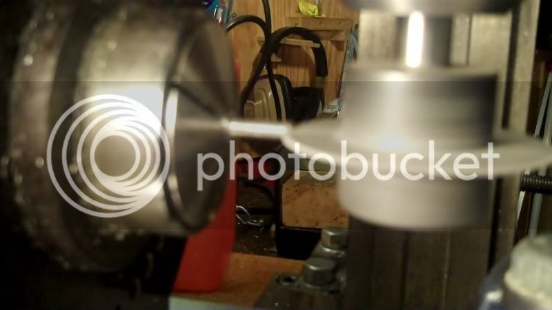
and mark it on the rod, to use a cutoff tool on it,
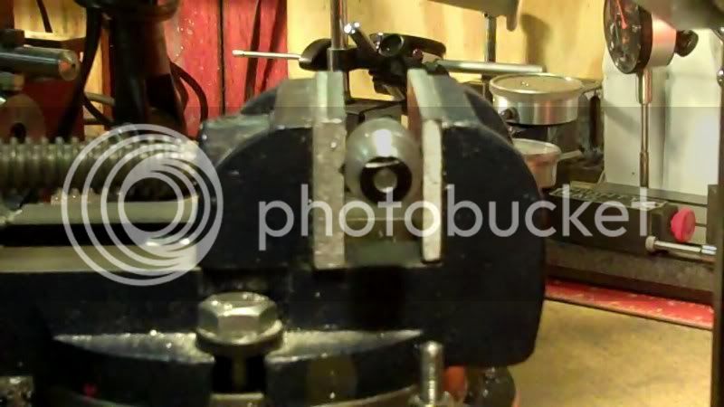
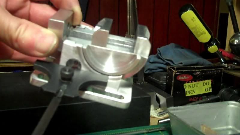
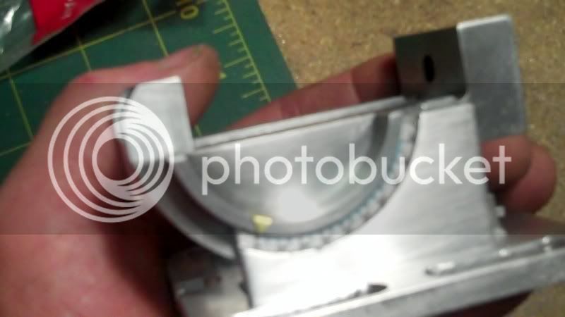
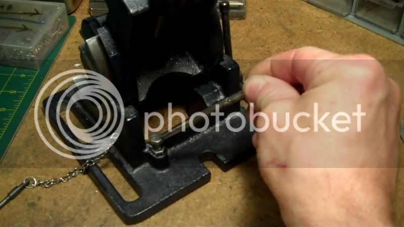
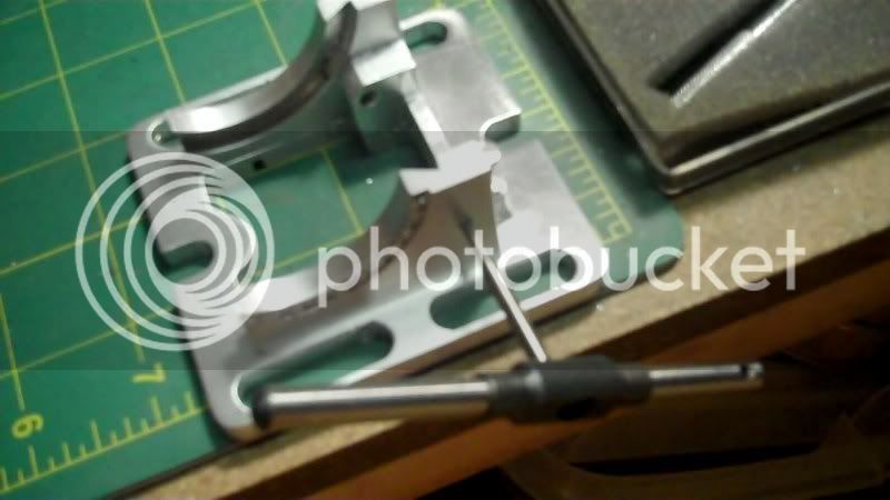
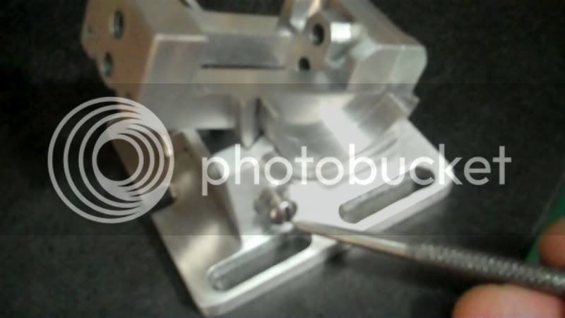
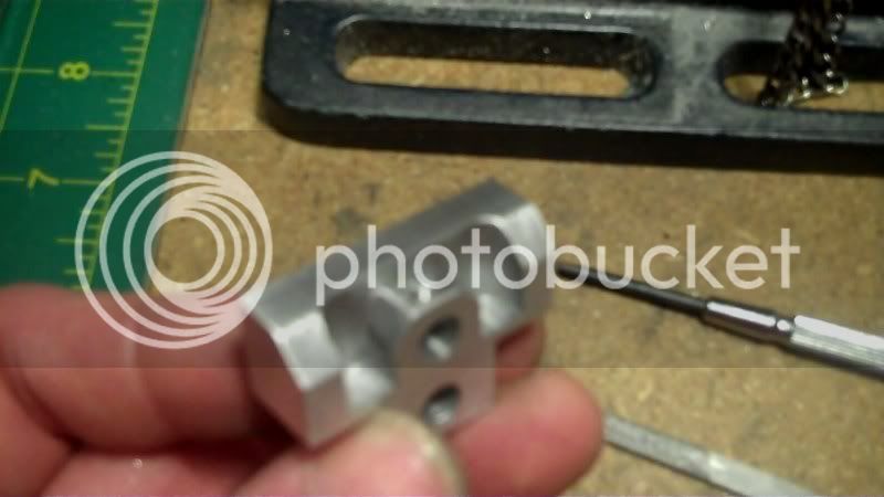
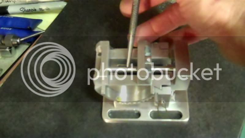
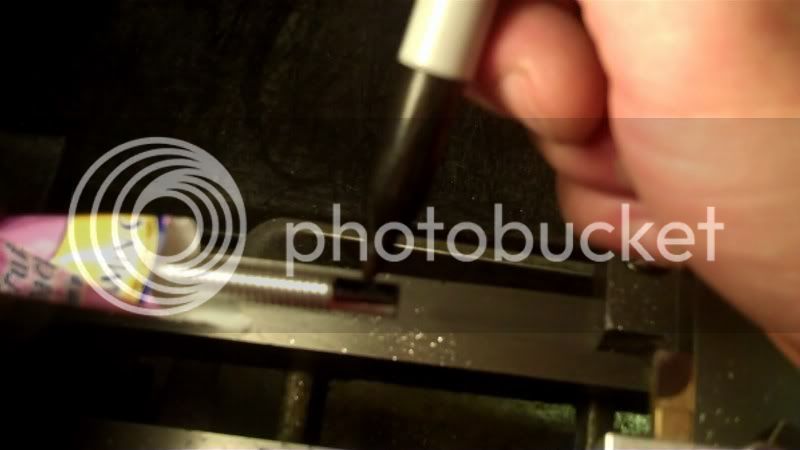
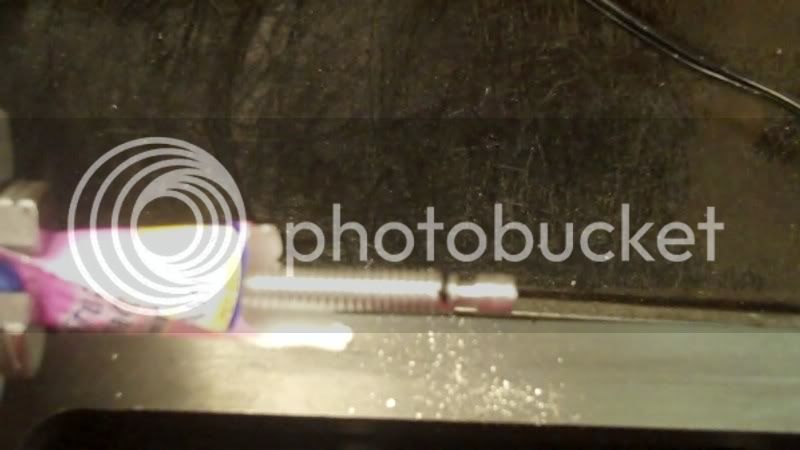
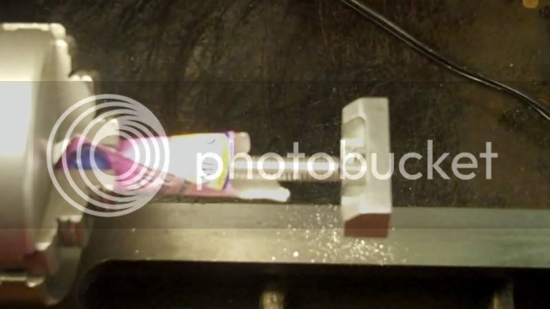
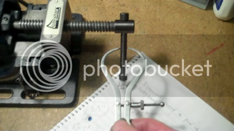
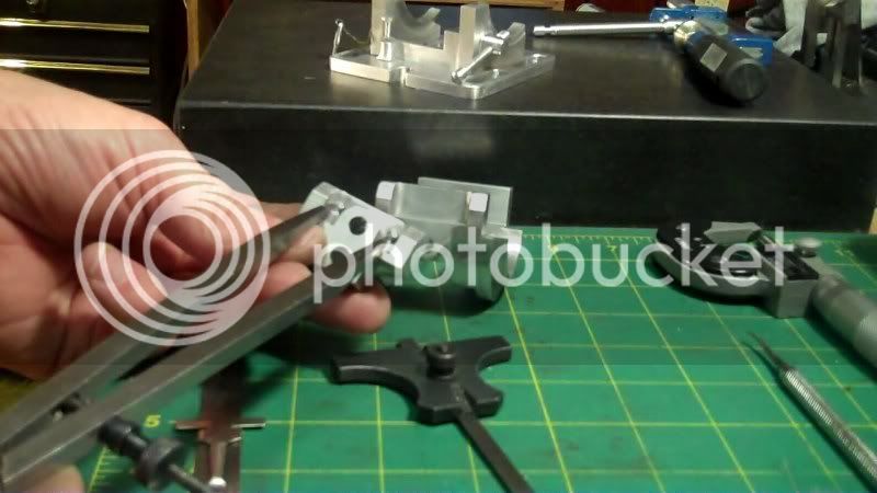
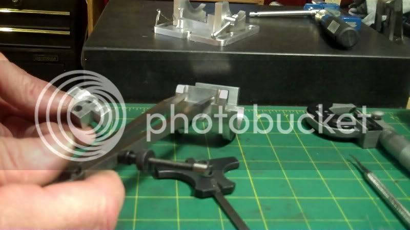
This tightens up fairly well, and does not do any damage to the top dovetail slide, so it fits quite well, here I'm using a 10-32 screw to test the locking part of it.
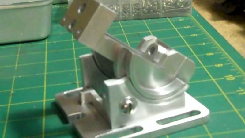
Now that I can lock it pretty good, next to do on this, will be to make the pointer for it, and install it, then using the pointer and guage, and locking mechanism, together I could then drill the appropriate indexing holes, then it will be time to work on the lathe parts of this model.
As well as some soft jaws for it too.
Still have some more finishing details to do to it yet.
Have fun in the shop...
Thanks for the compliment, and thanks for looking in.
------------------------------------
I put about an hour in this evening, to get the locking mechanism built.
I machined a piece of aluminum rod, down to 1/2" dia. and drilled a thru hole to fit a body diameter screw of 10-32..
The only way I could think of to mark the location of the dovetail cut was to put this blank into it's hole, and mark whwere it sticks thru on the inside like this.
Then line it up in my milling vice
and cut the dovetail into it.
Now to take a depth measurement
and mark it on the rod, to use a cutoff tool on it,
This tightens up fairly well, and does not do any damage to the top dovetail slide, so it fits quite well, here I'm using a 10-32 screw to test the locking part of it.
Now that I can lock it pretty good, next to do on this, will be to make the pointer for it, and install it, then using the pointer and guage, and locking mechanism, together I could then drill the appropriate indexing holes, then it will be time to work on the lathe parts of this model.
As well as some soft jaws for it too.
Still have some more finishing details to do to it yet.
Have fun in the shop...
- Joined
- Dec 5, 2009
- Messages
- 510
- Reaction score
- 47
Hello,
Another hour's work this evening in my shop.
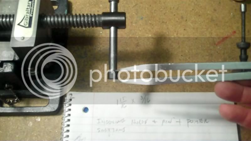
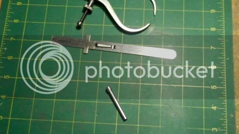
I'm making this angle guage pointer
so using some hobby shop brass sheet
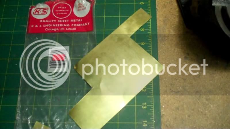
I can make this part from.
Take some measurements on the model to know how big to make the pointer length
as well as actual width measurements on the original
so I can scale it down
sketch it on the workpiece
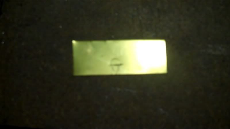
and cut it out.
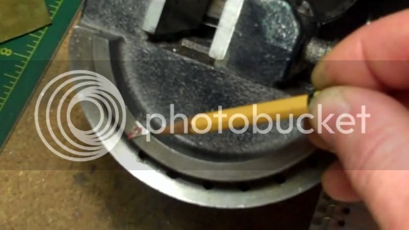
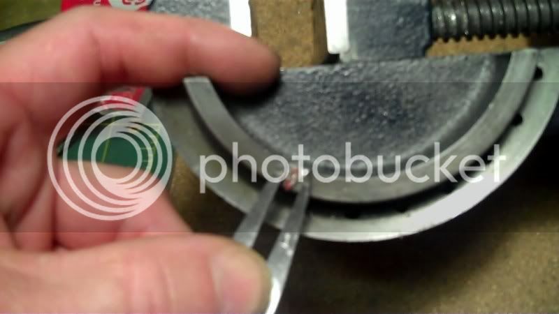
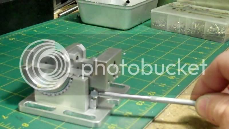
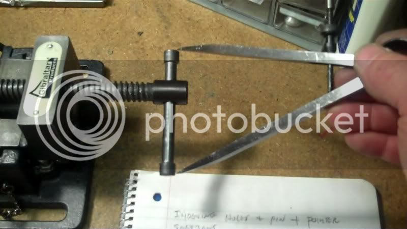
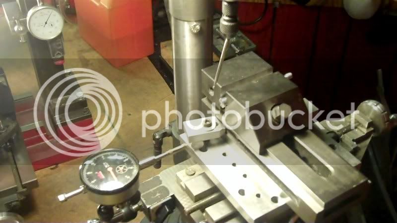
Now I need to adjust the angle of the model vise, to a zero level, the best way to do that is to use a travel indicator, and sweep it from front to back on the model vise rail. To get a zero reading.
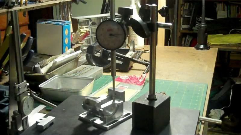
Now I can mark the zero on the model
to know where to put the pointer piece, using contact cement.
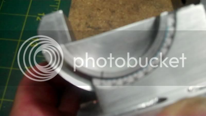
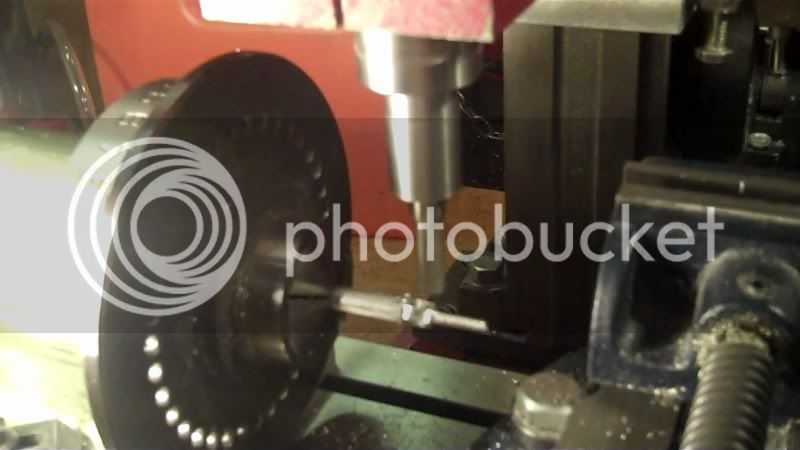
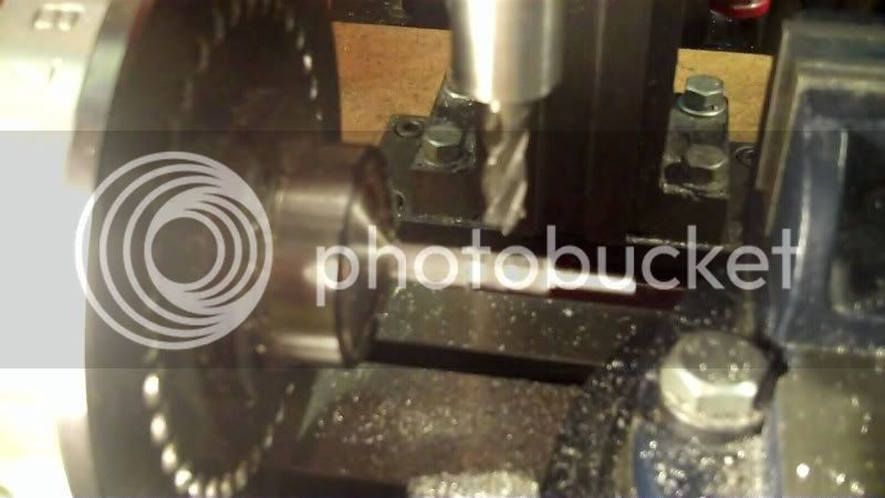
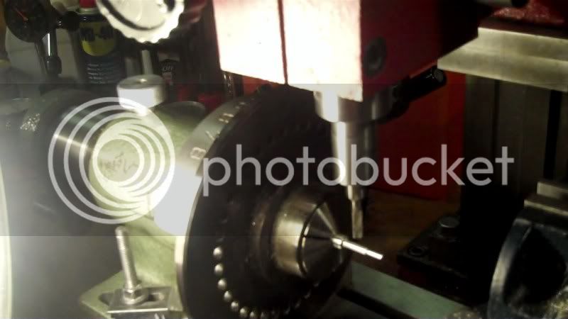
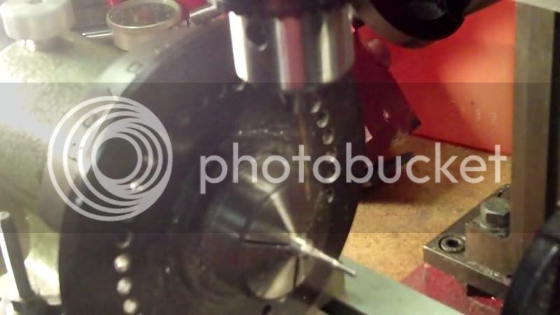
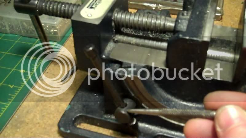
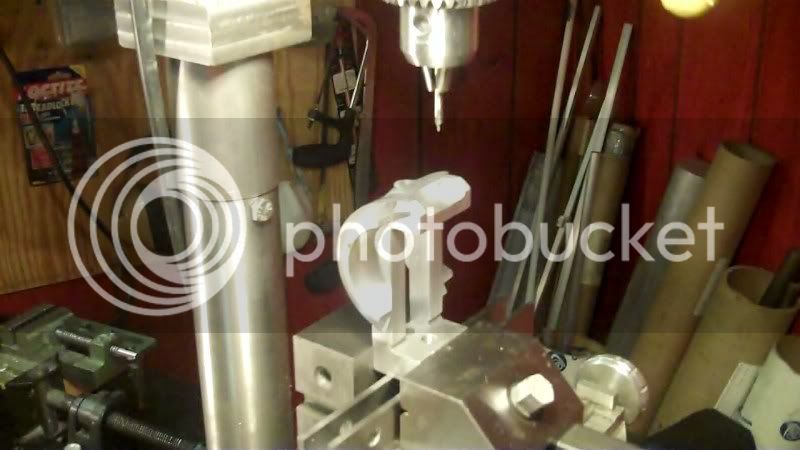
with the model vise locked in position with the pointer on the zero, I can set it up in my drill press, to drill the indexing holes.
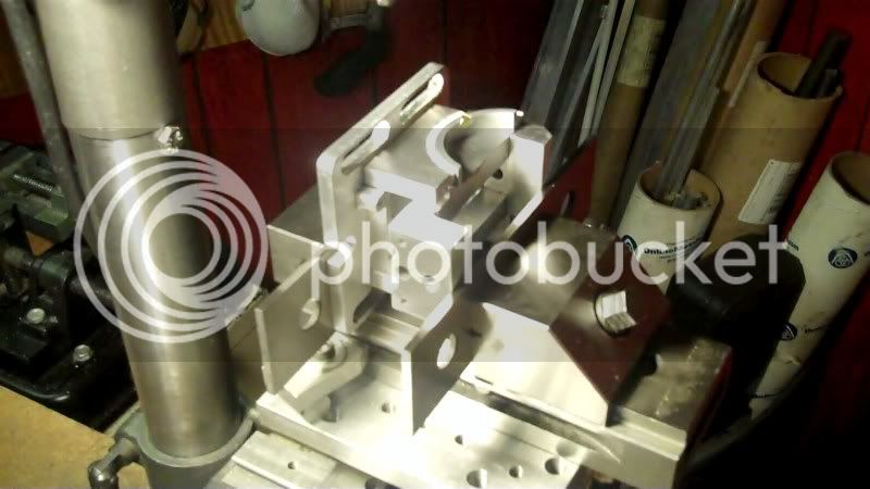
the first hole drilled, this is the zero angle indexed hiole. Also the main index pin hole in the frontice piece.
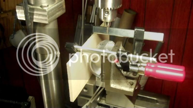
every 15* another indexing hole is drilled in.
until a full 90* is reached.
to finish the base of this model, looks like indexing pin and chain, and locking bar, and zero adjust bolt, which is pretty much all lathe work.
Have fun in the shop...
Another hour's work this evening in my shop.
I'm making this angle guage pointer
so using some hobby shop brass sheet
I can make this part from.
Take some measurements on the model to know how big to make the pointer length
as well as actual width measurements on the original
so I can scale it down
sketch it on the workpiece
and cut it out.
Now I need to adjust the angle of the model vise, to a zero level, the best way to do that is to use a travel indicator, and sweep it from front to back on the model vise rail. To get a zero reading.
Now I can mark the zero on the model
to know where to put the pointer piece, using contact cement.
with the model vise locked in position with the pointer on the zero, I can set it up in my drill press, to drill the indexing holes.
the first hole drilled, this is the zero angle indexed hiole. Also the main index pin hole in the frontice piece.
every 15* another indexing hole is drilled in.
until a full 90* is reached.
to finish the base of this model, looks like indexing pin and chain, and locking bar, and zero adjust bolt, which is pretty much all lathe work.
Have fun in the shop...
- Joined
- Dec 5, 2009
- Messages
- 510
- Reaction score
- 47
Hello,
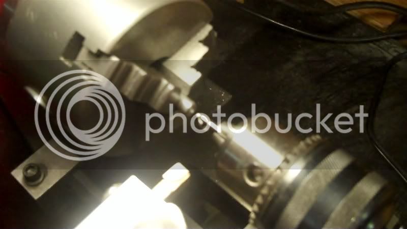
Today starts the lathe work, on the model's base features.
Start with making the zero adjustment bolt and nut.
which will go here on the model
There made from aluminum round bar stock,
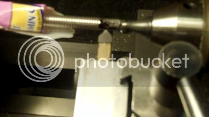
The process begins:

and fitted in its position.
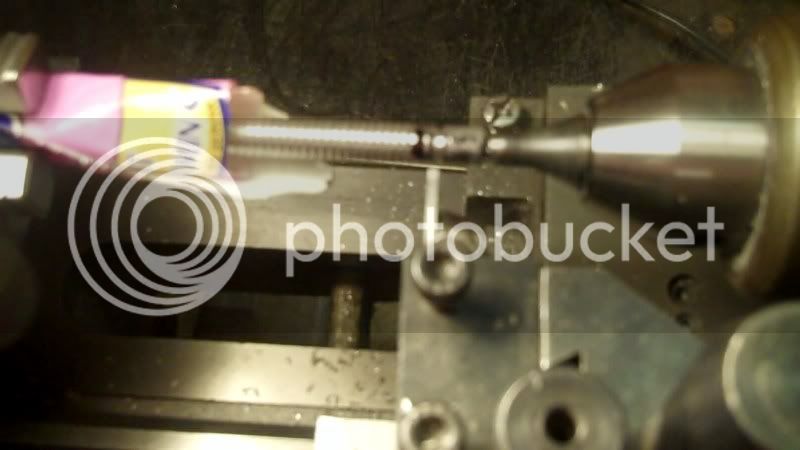
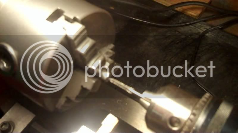
Now the indexing pin
and its process
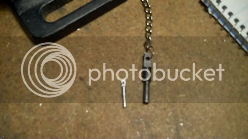
and the chain connector
all these pieces are from aluminum round stock
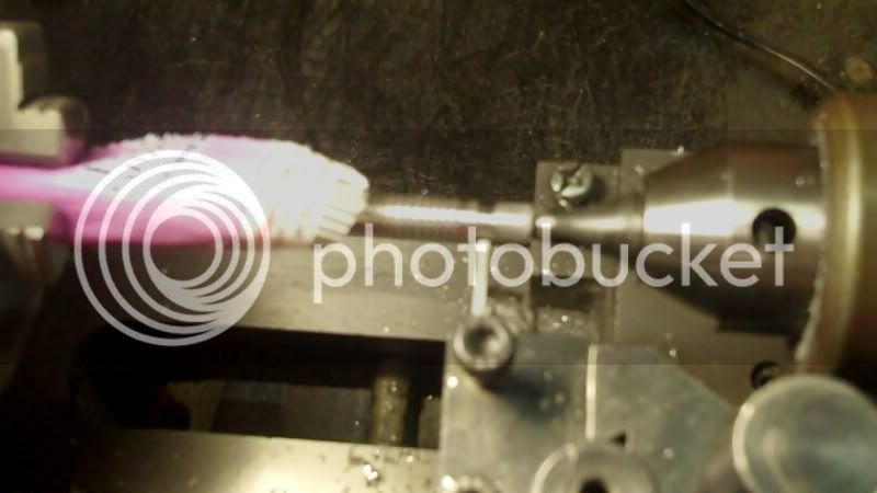
its process

both index pin and connector
need to tap into the front, for the chain connector, 2-56 thread.
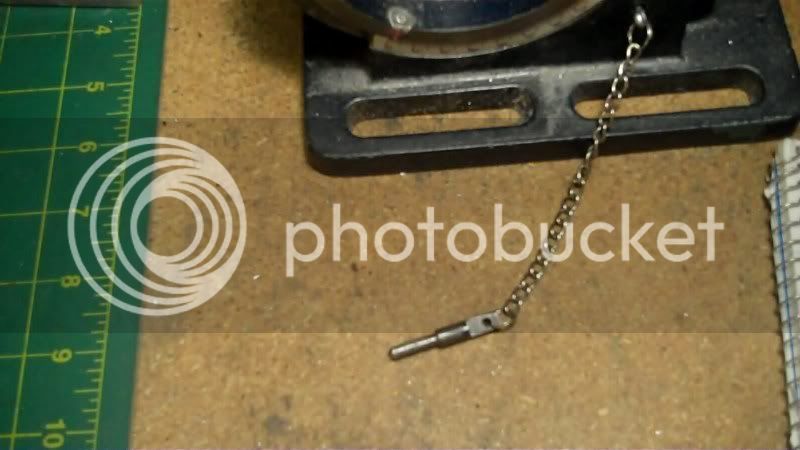
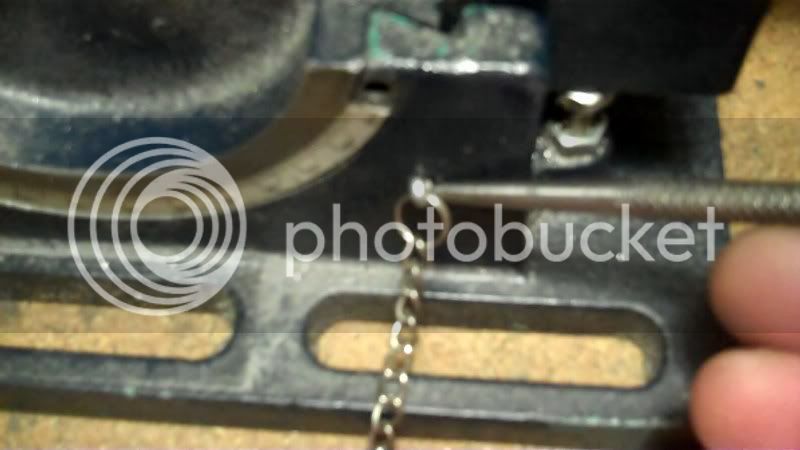
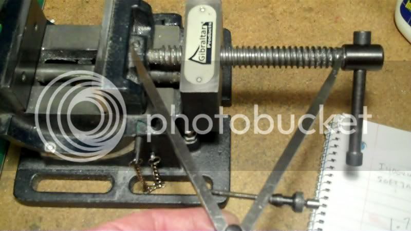
I don't have any model chain on hand, so I'm using dark green enamaled wire to substitute,
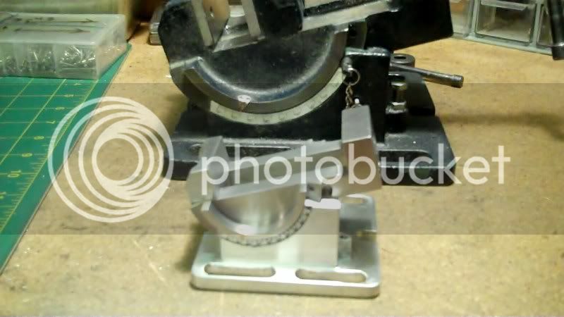
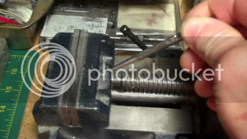
the indexing pin is now connected to the connector, via the wire chain and the pin is in place on the 30* angle guage.
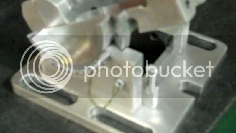
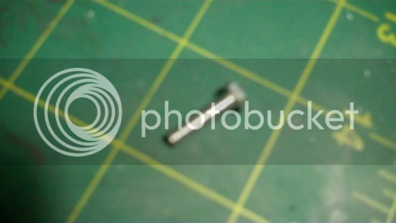
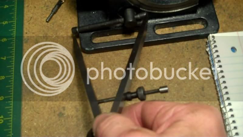
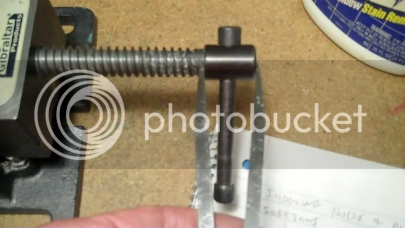
Here is the temporary 10-32 screw used to test the locking mechanism on the model.
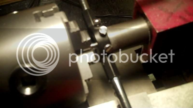
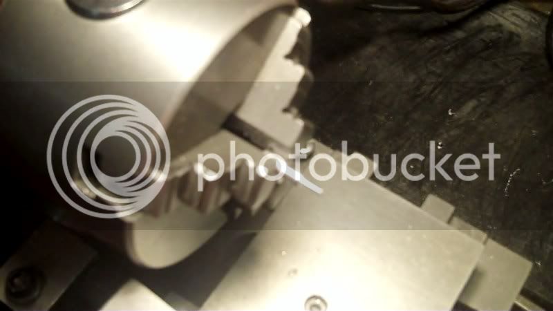
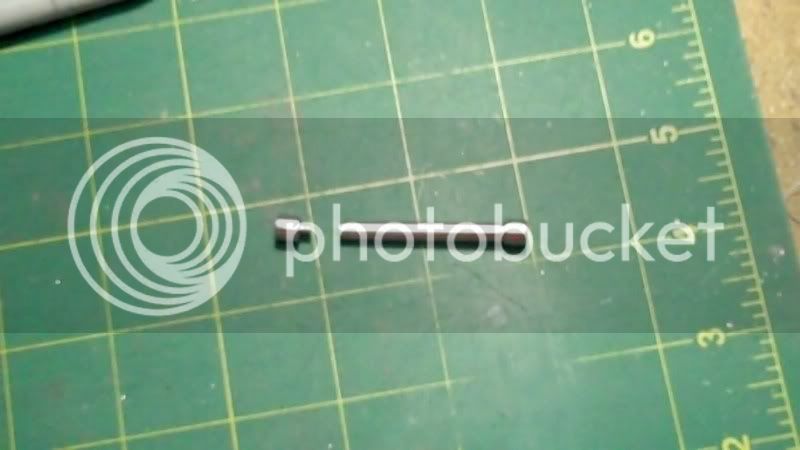
I'm going to replace it now with the handle system as shown on the original
start with the locking screw part
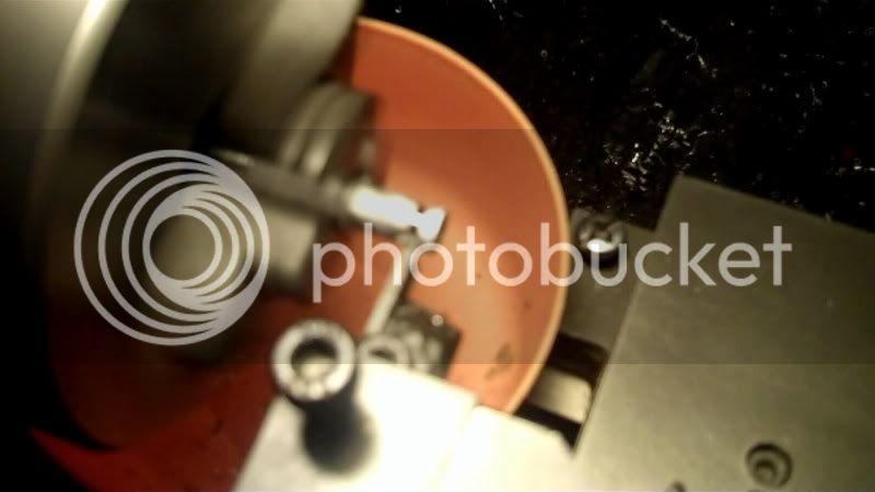
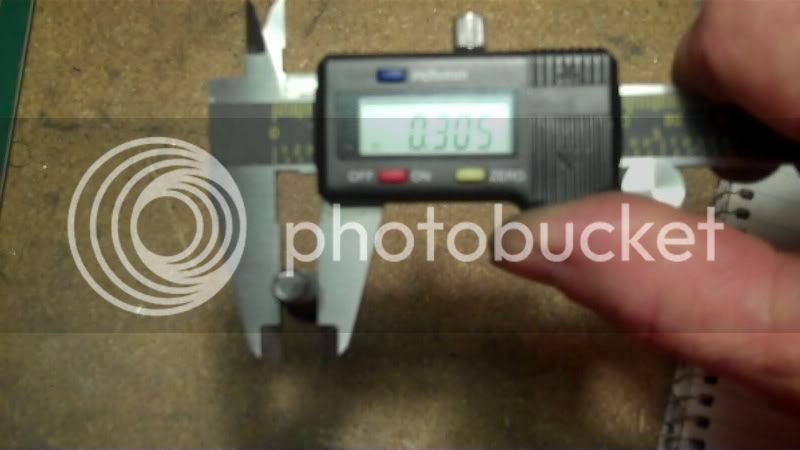
I need to check the dia. so as to scale it down to know what size hole
to bore into the workpiece. to recieve the handle bar.
that part done.
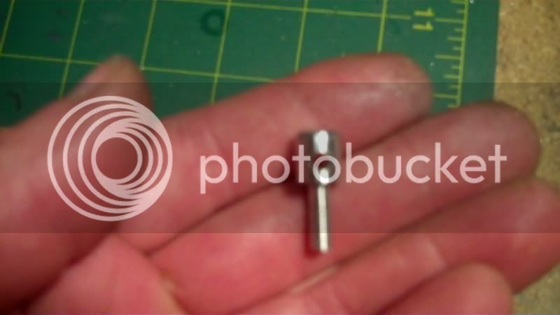
and in place
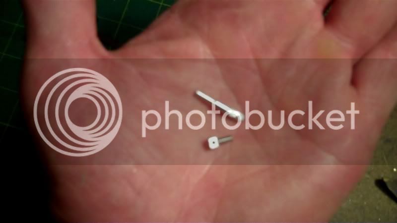
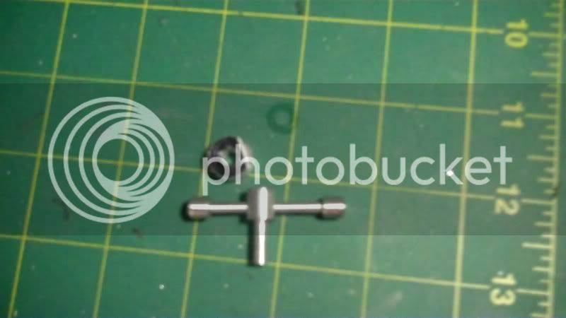
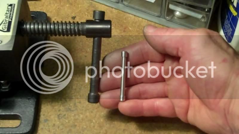
now the last part is the handle itself.
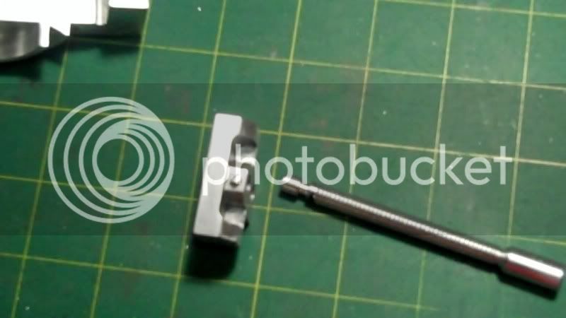
This consists af the entire locking mechanism, the dovetail locking gib bushing at the top, the locking screw, and the handle bar, the handle bar is made in two pieces
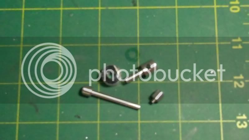
so it can be screwed together for final assembly to the locking screw.
OK,,,sit back and enjoy the rest of this slide show.
Ok that should take care of all the model pieces on the base system, now I can start moving into the vise top section, I'll need to take my time and not rush things to make this look and function properly.
Thanks for looking in,
Have a great day..
Today starts the lathe work, on the model's base features.
Start with making the zero adjustment bolt and nut.
which will go here on the model
There made from aluminum round bar stock,
The process begins:
and fitted in its position.
Now the indexing pin
and its process
and the chain connector
all these pieces are from aluminum round stock
its process
both index pin and connector
need to tap into the front, for the chain connector, 2-56 thread.
I don't have any model chain on hand, so I'm using dark green enamaled wire to substitute,
the indexing pin is now connected to the connector, via the wire chain and the pin is in place on the 30* angle guage.
Here is the temporary 10-32 screw used to test the locking mechanism on the model.
I'm going to replace it now with the handle system as shown on the original
start with the locking screw part
I need to check the dia. so as to scale it down to know what size hole
to bore into the workpiece. to recieve the handle bar.
that part done.
and in place
now the last part is the handle itself.
This consists af the entire locking mechanism, the dovetail locking gib bushing at the top, the locking screw, and the handle bar, the handle bar is made in two pieces
so it can be screwed together for final assembly to the locking screw.
OK,,,sit back and enjoy the rest of this slide show.
Ok that should take care of all the model pieces on the base system, now I can start moving into the vise top section, I'll need to take my time and not rush things to make this look and function properly.
Thanks for looking in,
Have a great day..
SWEET!!!!!!!!!!!!
- Joined
- Dec 5, 2009
- Messages
- 510
- Reaction score
- 47
Steve, Don,
Thankyou guys for looking in, and the compliments.
-------------------------------------------------------------
Now it's time to machine a set screw
which will go here
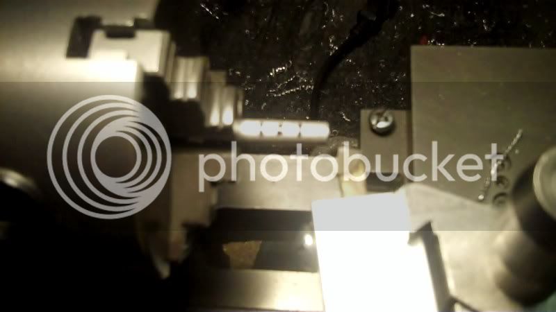
as like this, preparing the moveable jaw for the setscrew
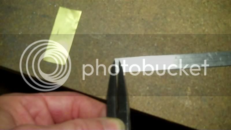
and now the set setscrew, made from aluminum round rod
make a screwdriver slot
mini hacksaw it off
and put it in it's place on the moveable jaw.
now the stabilizing bar
and on the model
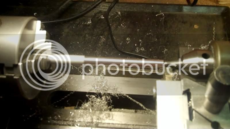
Now to make the leadscrew
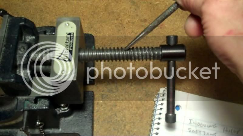
my leadscrew will be 5/16-18 so need to secure the body dimensions from a cap screw of thast size.
now take all the leadscrew dimensions from the original
And the fabrication begins
check for threaded fit, with the model itself.
now to make the relief at the end of the leadscrew that goes into the moveable jaw at this area
and on the model
get all the dimensions needed from the model workpiece, such as hole depth
transfer it to the leadscrew
and machine it to size
check for sliding fit
now to locate where the setscrew will be located on the leadscrew
theres the mark left by the setscrew bearing down on it here
now I need to cut a recess in this area for the setscrew to float inside of it
now to check to make sure the slot (recess is deep enough to allow the setscrew to penetrate the empty space far enough
here are both ppieces ready for assembly
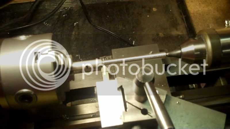
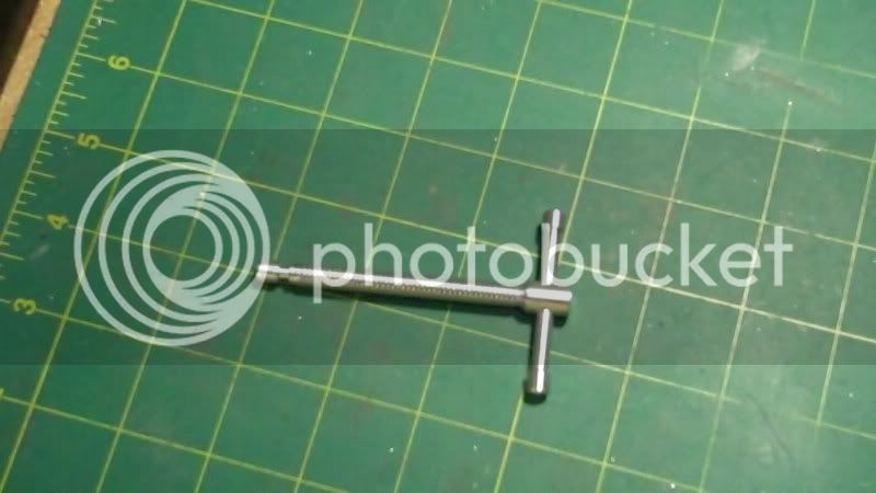
now to make the handle for the leadscrew,
I need to drill and tap a threaded hole on one end to allow a cap to be put on after the handle is in place on the leadscrew.
cut to final length of the handle before second endcap is put on.
now the endcap is made
temp. put together
now to locate and drill a hole in the leadscrew to recieve the handle subassembly.
Now I turn my attention to machining the softjaws,
I need to fabricate 4 cap screws like the original shown here, these hold the softjaws on the hard jaws,
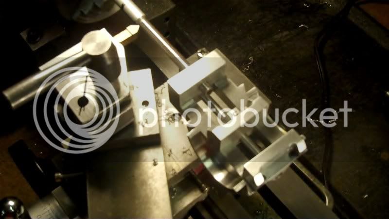
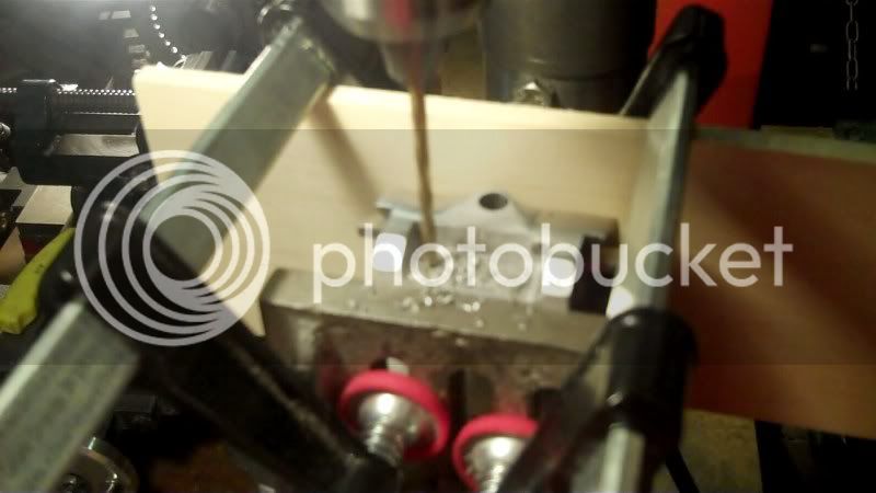
but first I need to drill the thru holes in the hardjaws on the model, so I'll center each hole in between the recesses cutout on the moveable jaw first,
with everything set up and located I can drill the body diameter holes first for 4-40 screws
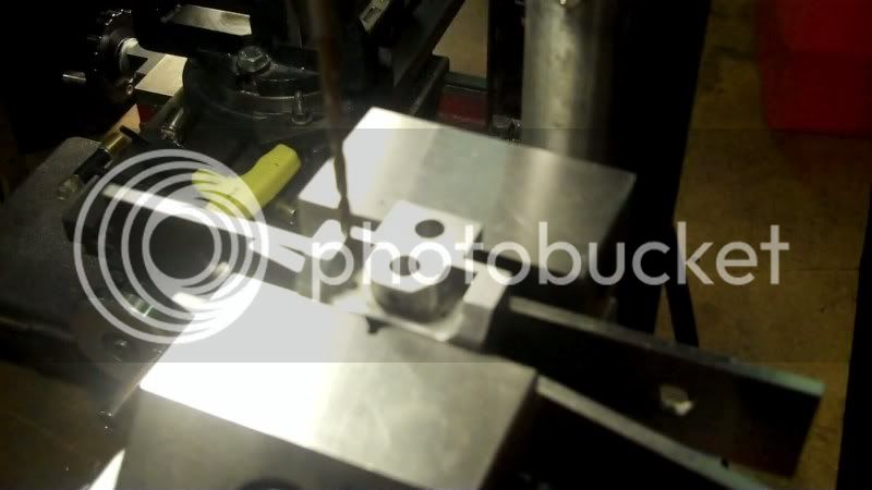
Now I need to counterbore for the capscrews , I don't want to use an endmill, it may grab the workpiece, in my drillpress, so I opted, to use a dremel round profile burr, as shown here
it did a nice job of cutting very smoothly a CB.
Now when I made those last two holes, I used the recesses machined in the workpiece to center the holes, however, on the front jaw, there is one continuous recess machined throughout, therefor, I need to use the center of the inside recess as the reference point to work off of, but first I need to transfer the distance each hole is off center of the moveable jaw here,
to make these holes line up with the fixed jaw over here,
now the hole model top assembly containing the fixed jaw, is setup in the drillpress, for hole locations
and now the drilling process is underway
Next will be the making and assembly of the softjaws on the model, and do some final finishing work and it will be a completed model.
I will then post a picture of it in the next post, with a short video clip of it, being put through it's mechnaical movements.
Thanks for looking in.
Have a great day..
Thankyou guys for looking in, and the compliments.
-------------------------------------------------------------
Now it's time to machine a set screw
which will go here
as like this, preparing the moveable jaw for the setscrew
and now the set setscrew, made from aluminum round rod
make a screwdriver slot
mini hacksaw it off
and put it in it's place on the moveable jaw.
now the stabilizing bar
and on the model
Now to make the leadscrew
my leadscrew will be 5/16-18 so need to secure the body dimensions from a cap screw of thast size.
now take all the leadscrew dimensions from the original
And the fabrication begins
check for threaded fit, with the model itself.
now to make the relief at the end of the leadscrew that goes into the moveable jaw at this area
and on the model
get all the dimensions needed from the model workpiece, such as hole depth
transfer it to the leadscrew
and machine it to size
check for sliding fit
now to locate where the setscrew will be located on the leadscrew
theres the mark left by the setscrew bearing down on it here
now I need to cut a recess in this area for the setscrew to float inside of it
now to check to make sure the slot (recess is deep enough to allow the setscrew to penetrate the empty space far enough
here are both ppieces ready for assembly
now to make the handle for the leadscrew,
I need to drill and tap a threaded hole on one end to allow a cap to be put on after the handle is in place on the leadscrew.
cut to final length of the handle before second endcap is put on.
now the endcap is made
temp. put together
now to locate and drill a hole in the leadscrew to recieve the handle subassembly.
Now I turn my attention to machining the softjaws,
I need to fabricate 4 cap screws like the original shown here, these hold the softjaws on the hard jaws,
but first I need to drill the thru holes in the hardjaws on the model, so I'll center each hole in between the recesses cutout on the moveable jaw first,
with everything set up and located I can drill the body diameter holes first for 4-40 screws
Now I need to counterbore for the capscrews , I don't want to use an endmill, it may grab the workpiece, in my drillpress, so I opted, to use a dremel round profile burr, as shown here
it did a nice job of cutting very smoothly a CB.
Now when I made those last two holes, I used the recesses machined in the workpiece to center the holes, however, on the front jaw, there is one continuous recess machined throughout, therefor, I need to use the center of the inside recess as the reference point to work off of, but first I need to transfer the distance each hole is off center of the moveable jaw here,
to make these holes line up with the fixed jaw over here,
now the hole model top assembly containing the fixed jaw, is setup in the drillpress, for hole locations
and now the drilling process is underway
Next will be the making and assembly of the softjaws on the model, and do some final finishing work and it will be a completed model.
I will then post a picture of it in the next post, with a short video clip of it, being put through it's mechnaical movements.
Thanks for looking in.
Have a great day..
- Joined
- Dec 5, 2009
- Messages
- 510
- Reaction score
- 47
Thankyou Brock, for the compliment
-------------------------------------
Hello everyone,
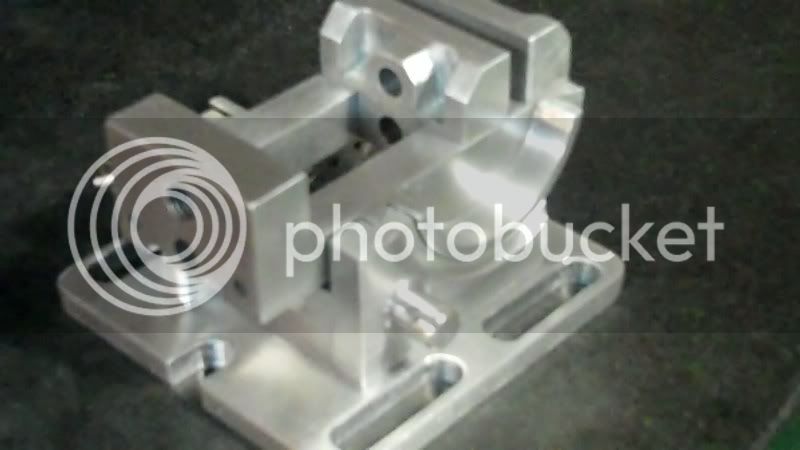
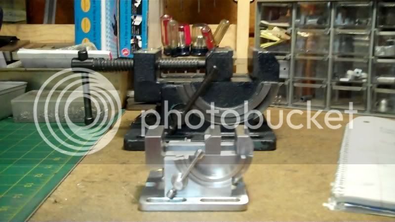
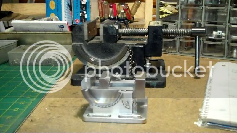
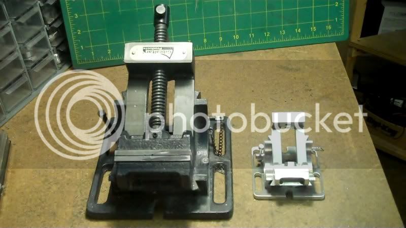
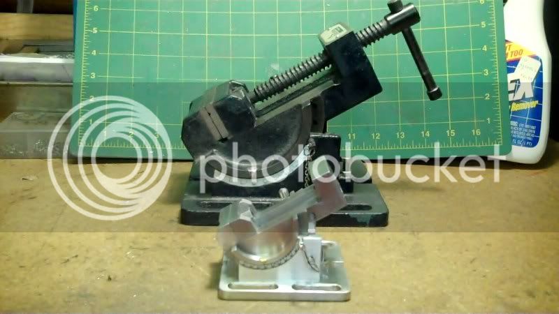
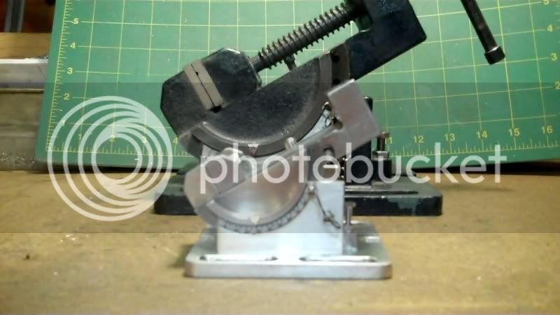
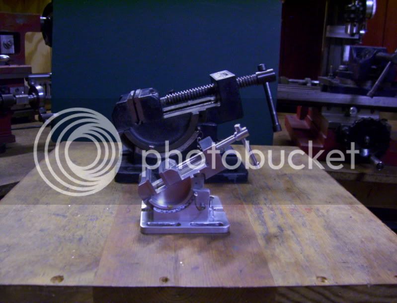
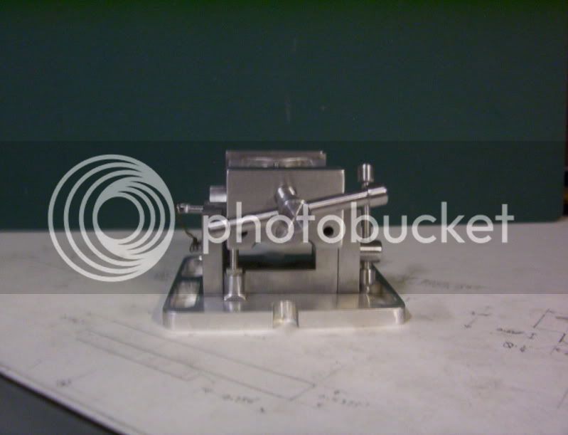
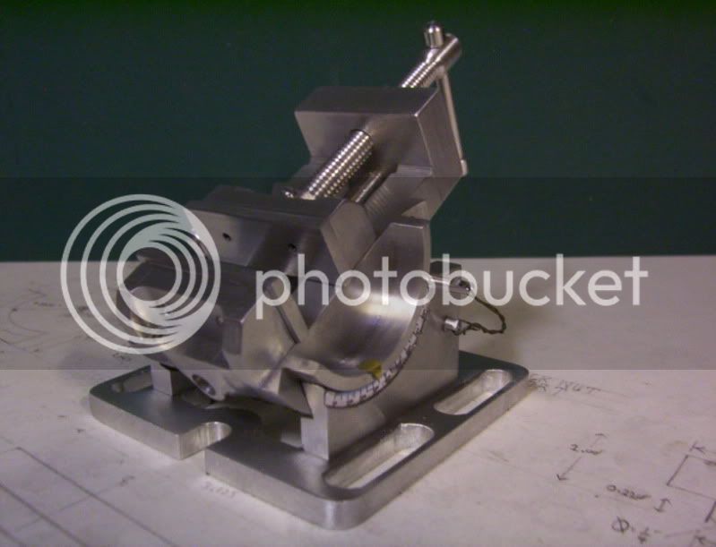
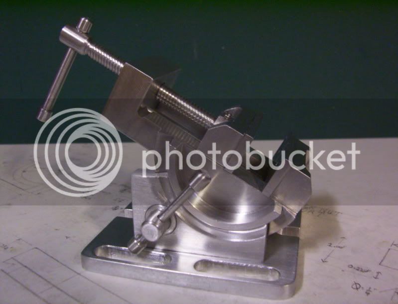
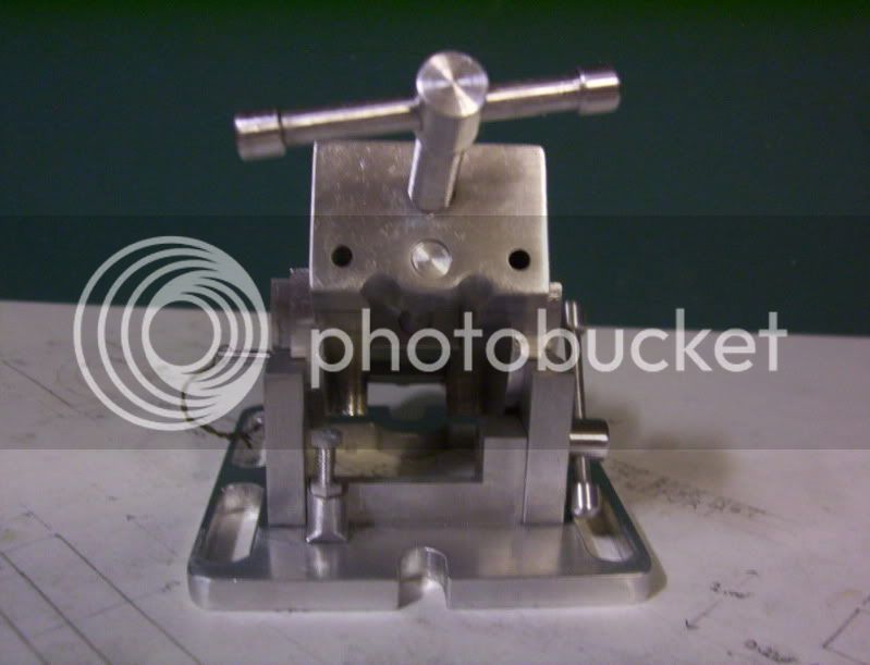
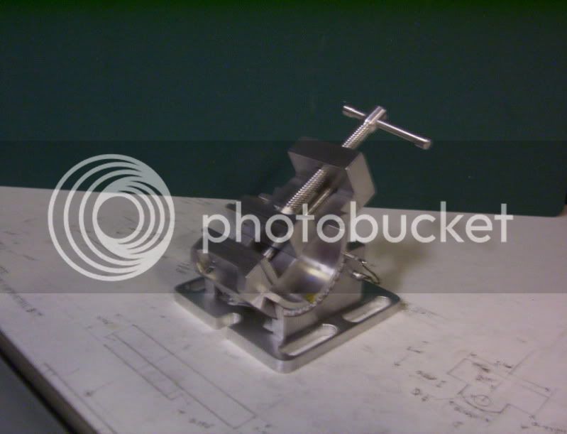
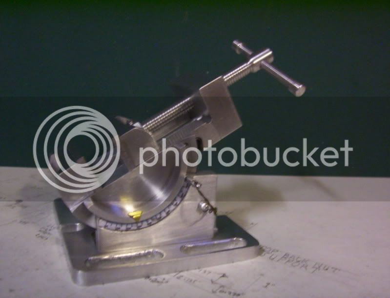
This project is now completed, it was an enjoyable project, it had a major challenge, which was doing the radial dovetailing, figuring a way to hold the workpieces to machine those.
Also I tried to keep as much to scale as possible, for me, as well as keeping as much of the details incorporated into the model, as the original.
The screw fastneners I used to assemble the workpieces are not part of the original, because the original used a casting, so those fasteners are commercialy available and those I used.
But any other fastners used in the original, I fabricated from aluminum round stock, as these were scaled down versions, as well as part of the feaures needed to be modeled.
For example,The hex bolt and nut for zero adjustment as well as any setscrews, and capscrews.
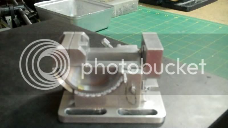
To substitute for the chain, used to keep the index pin, I used some solid green enameled wire, which works ok for this application.
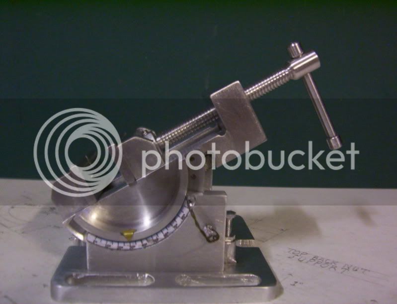
I also incorporated the same components used in the locking device, which utilizes a locking dovetailed gib bushing, and bolt and threaded block in the back of the unit.
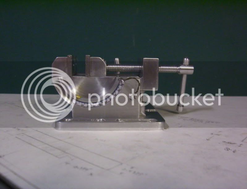
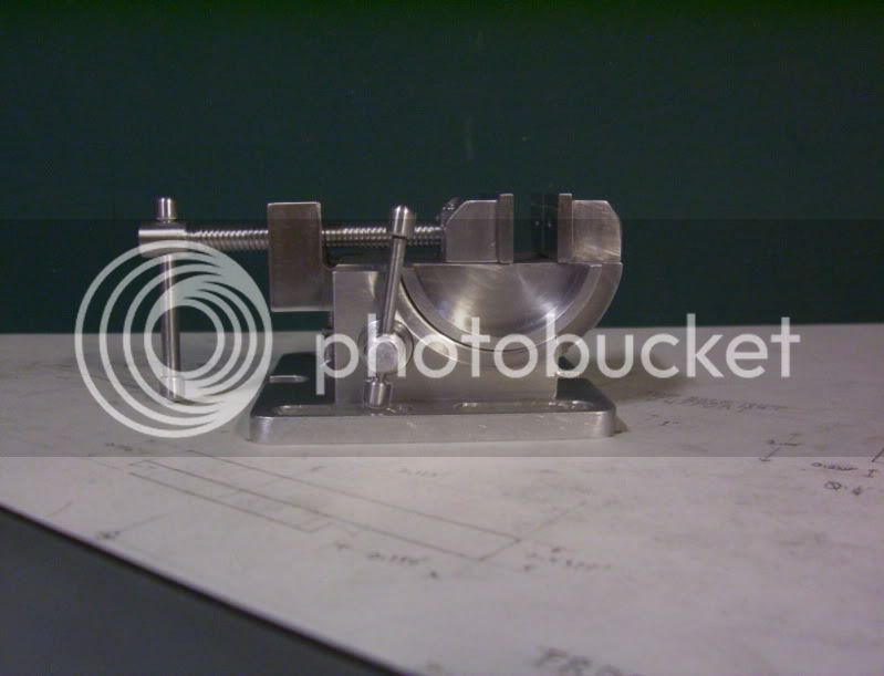
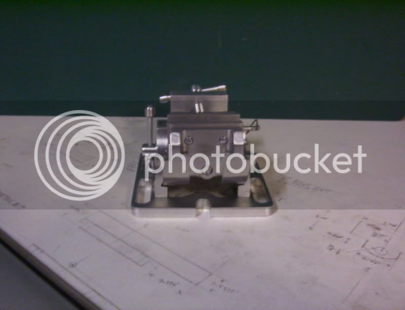
Here is a series of pictures taken with my digital camera, for better clarity, of the finished model.
Thankyou everyone for following along in this thread, and thankyou for the compliments throughout this thread.
Have a great day.
-------------------------------------
Hello everyone,
This project is now completed, it was an enjoyable project, it had a major challenge, which was doing the radial dovetailing, figuring a way to hold the workpieces to machine those.
Also I tried to keep as much to scale as possible, for me, as well as keeping as much of the details incorporated into the model, as the original.
The screw fastneners I used to assemble the workpieces are not part of the original, because the original used a casting, so those fasteners are commercialy available and those I used.
But any other fastners used in the original, I fabricated from aluminum round stock, as these were scaled down versions, as well as part of the feaures needed to be modeled.
For example,The hex bolt and nut for zero adjustment as well as any setscrews, and capscrews.
To substitute for the chain, used to keep the index pin, I used some solid green enameled wire, which works ok for this application.
I also incorporated the same components used in the locking device, which utilizes a locking dovetailed gib bushing, and bolt and threaded block in the back of the unit.
Here is a series of pictures taken with my digital camera, for better clarity, of the finished model.
Thankyou everyone for following along in this thread, and thankyou for the compliments throughout this thread.
Have a great day.
Bravo Hobby!
I really enjoyed this thread. Love it when someone goes off in a different direction to create something original. Great idea and execution. Thanks for posting progress so we could follow along.
I really enjoyed this thread. Love it when someone goes off in a different direction to create something original. Great idea and execution. Thanks for posting progress so we could follow along.
- Joined
- Dec 5, 2009
- Messages
- 510
- Reaction score
- 47
Steve:
I'm glad you enjoyed following along in this thread.
Thankyou for your perseverance, and the encouraging compliments.
---------------------------------------------------------------------------------
Dave:
Thankyou for your encouraging compliments, and your perseverance also.
and yes also, thanks for the Karma point.
----------------------------------------------------------------------------------
Kel::
Thankyou also for your perseverance, and the encouragements you gave me along the way.
This project was done strictly as a model, not intended for any shop use, but just to display along with my other projects.
------------------------------------------------------------------------------------
I wanted to see if I have enough experiance in my shop now, to be able to take my time and build as close as possible a scaled version of a mechanical device.
Building to scale is fun to do, although my scale versions are not entirely precise as more seasoned modelers are able to do in this hobby.
But this is just a start, now I'll try to improve on the concepts of scale modeling, as I learn by doing more projects, in this hobby.
Thanks guys for looking into my thread
and all the encouragements you shared with me.
Have a great day....
- Joined
- Jul 16, 2007
- Messages
- 2,993
- Reaction score
- 1,061
Great work Hobby,
I agree with Steve. It' nice to see a different type of project worked on. Of course why wouldn't I say that, I like doing the same types of things. Very nice documentation and execution.
gbritnell
I agree with Steve. It' nice to see a different type of project worked on. Of course why wouldn't I say that, I like doing the same types of things. Very nice documentation and execution.
gbritnell
zeeprogrammer
Well-Known Member
- Joined
- Mar 14, 2009
- Messages
- 3,362
- Reaction score
- 13
Beautiful work and a great thread. Very enjoyable.
I like these kinds of projects...it makes one think about more possibilities.
I like these kinds of projects...it makes one think about more possibilities.
dsquire
Well-Known Member
- Joined
- Mar 18, 2008
- Messages
- 980
- Reaction score
- 15
Hobby
I haven't posted about this before but I have been watching if come to life as you worked on it. You can be proud of your accomplishment and I look forward to see what your next challenge will be. Thanks for the excellent way in which you presented the build log to us. :bow:
Cheers")
Don
I haven't posted about this before but I have been watching if come to life as you worked on it. You can be proud of your accomplishment and I look forward to see what your next challenge will be. Thanks for the excellent way in which you presented the build log to us. :bow:
Cheers
Don
- Joined
- Dec 5, 2009
- Messages
- 510
- Reaction score
- 47
Carl:
Thankyou for the complement, and folowing along,
Your right, I know what you mean, about the more possibilities,
even the very simple things of todays manufacturing, may be simple to make comercially,
but in the "hobby" field of machining, it can provide some quite unusual challenges to try to replicate that same thing.
Don:
Thankyou, also, for the very encouraging complement, and following along in this thread.
Thanks guys,
have a great day.
Similar threads
- Replies
- 413
- Views
- 42K