Building a twin cylinder inline i.c. engine.

Home Model Engine Machinist Forum

Help Support Home Model Engine Machinist Forum:

This site may earn a commission from merchant affiliate links, including eBay, Amazon, and others.
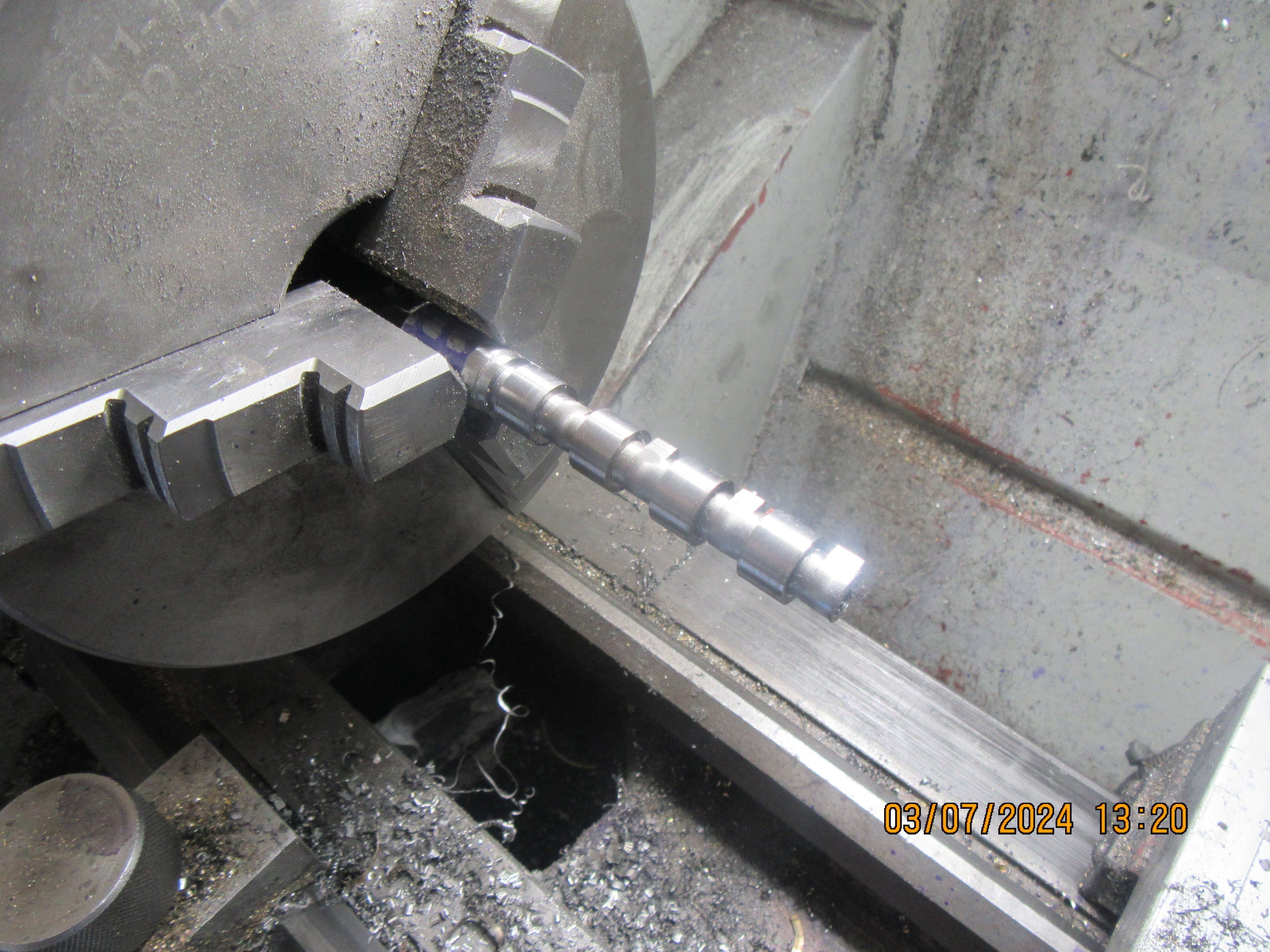
Can you "unharden" 01 steel that has been heated to cherry red and then quenched? I want to add two more threaded holes for set screws to my cams, but right now they are harder than the devil's horn. After the threaded holes have been added I want to reharden them. Seems to me that I've read somewhere that you can, but I've never done it.---Brian
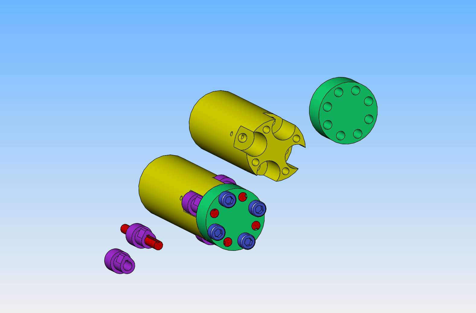
 
Could be that it can be used with a bit more fiddling also for the constant radius part of the cams?
Maybe a derivative device to allow finishing on a grinding machine of the same area.
 
Hello Brian

I don't know what type 01 steel is, but hardened steel can usually always be soft annealed.
If it is a water or oil hardening steel, it can be hardened again.
Steel types that are carburized and case-hardened are more problematic.
They need to be re-carburized.

Dieter
 
I would suggest making a test piece and hardening it.
Then soft annealing and drilling and cutting threads.
Maybe first a hardening test with a file, after soft annealing.

If everything goes well, only then with the cams.

Dieter
 
Simply Brian, take the bit of hard steel, cook red hot (not necessarily cherry red, just glowing is OK. Then bury in sand (dry sand is best!). Allow to cool SLOWLY, for annealing. Check afterwards with a file. repeat a few times if not enough the first time...? It is the faster quenching that hardens the steel, slower anneals it.. (I think? - I am not an expert... but have been a drip under pressure = Ex-Spurt!).
On forged parts for car axles, they use induction heating to a low red heat, then an air blast (after tuning the time for induction heating, time in the air blast, etc) and the air blast cools the outside quite quickly, for hardness for grinding, but leaves the core to cool much slower, so it is tougher not harder.
K2
 
Some more 3D CAD shows me that yes, I could build a fixture to turn the flanks on my cams. In fact, I could do one side of all four cams at once. Then I could flip all the cams over 180 degrees and do the other four sides all at once. Mind you, that would only machine the flanks. Then a second fixture which I haven't shown would be needed to stand the cams vertically in a 3 jaw chuck attached to my rotary table and mill the large diameter end which would be tangent to the flanks. Probably some light hand filing would be used to put a radius at the small diameter end. And that my friends is how it was done before cnc machining was available. Seems like a lot of work though.
TukTAE.jpg
 
Excellent Brian. But in Pre-CNC industrial volumes cast-iron camshafts were cut and finished on profile grinders that followed a master cam causing the grinding wheel to move in and out as the cam rotated slowly. Quite a different process to the hobby workshop. The grey iron cast camshafts were chill-hardened for the cam face metal before grinding. We (modellers) are more likely to machine and hand finish cam profiles on annealed steel and case harden afterwards. Everything is different to something as basic as your regular car engine.
But if you are good enough, you can simply file cams to the correct shape... then case harden and polish? - I knew a racer who used to do that, as he changed cam profiles a lot in the search for power and torque!
It depends on the true task. Is it overcoming difficult machining challenges? - Or is it just about making a running engine? - I think you like the machining challenges...
Well done!
K2
 
Do you really need radius flanks? slow running engine will be OK with flat flanks which are simple on a rotary table.
 
Hello Brian

I made this camshaft many years ago.
I made the cams by hand with a file.
For angle orientation, I made outlines on the pre-turned diameters.
It was a very complex job and took time.
The camshaft was then hardened and polished.

Dieter


nockenwelle.jpg


Simply Brian, take the bit of hard steel, cook red hot (not necessarily cherry red, just glowing is OK. Then bury in sand (dry sand is best!). Allow to cool SLOWLY, for annealing. Check afterwards with a file. repeat a few times if not enough the first time...? It is the faster quenching that hardens the steel, slower anneals it.. (I think? - I am not an expert... but have been a drip under pressure = Ex-Spurt!).
On forged parts for car axles, they use induction heating to a low red heat, then an air blast (after tuning the time for induction heating, time in the air blast, etc) and the air blast cools the outside quite quickly, for hardness for grinding, but leaves the core to cool much slower, so it is tougher not harder.
K2
Brian: You have a heat treat/pottery oven. Just put the parts in the oven and heat them to red hot and then lower the temperature slowly until you get down to probably 500°
 
Brian,
I have built many I.C. engines over the years, single, twin, triple ,4, 5, 6 and 8 cylinder configurations. All my cams are made from w-1 steel and left in the unhardened state. They all have flat flanks. The lifters ,even roller lifters are hardened. I was taught that as long as you don't run the same metal against itself the wear is negligible. Most of my engine have anywhere from 20-40 hours of running time on them with no noticeable wear. I think you're just uver complicating the whole thing!
 
George--I remember asking you this before a couple of years ago. I agree--I think I am over complicating the whole thing. I'm going to do up a set of cams with flat flanks and see what happens.---Brian
 
Brian,
I have built many I.C. engines over the years, single, twin, triple ,4, 5, 6 and 8 cylinder configurations. All my cams are made from w-1 steel and left in the unhardened state. They all have flat flanks. The lifters ,even roller lifters are hardened. I was taught that as long as you don't run the same metal against itself the wear is negligible. Most of my engine have anywhere from 20-40 hours of running time on them with no noticeable wear. I think you're just uver complicating the whole thing!
I agree !

Hi Brian.
It seems like you're bogged down in cam configurations and how to make cams (I read your other thread about CNC).
A lot of comments when an engine does not run, does not run well...all things related to lobes, radius....
Sometimes it helps to read other people's threads about how the engine might run, it gives you a more objective perspective.

https://www.homemodelenginemachinist.com/threads/back-to-work-on-my-ufo.32211/
 
Last edited:
An opinion.
I am human - with common faults - and often have to do something the wrong way before I overcome my stubborn attitude and listen to advice, or try a different way, or realise I am trying to achieve something that is simply beyond my capability, or simply to learn the problems of the wrong way, so I can do it right next time.
The right way can be different between individuals because we have different goals.
Maybe "learning new machining ways" is the goal? - or maybe "completing the engine so it runs" is the goal? - Learning and hobbies are about fun. So the right solution varies depending upon who we are and what we want to achieve. -and maximising the fun in the process, often by challenging ourselves to do something new or different.
But lots of different suggestions can confuse the issue.
Brian will surely decide his way, which will be the right way for his objectives, and, as always, finish with a good engine.
Watch this space.
K2
 
Today it was time for another kick at the can---So--I made four new cams without radiused flanks. The point of the cam nearest to the chuck is pointed the other way, because I had to take the workpiece out of the chuck, then put it back in. The angular orientation doesn't matter at this point, because the cams will all become separate pieces after I finish drilling and tapping set screw holes. And as a side note--The first set of cams I made only had two set screws at 90 degrees. When I went to tighten the screws against the camshaft, the set screw holes were on the wrong side and I couldn't access them to tighten them. These new cams will have four set screw holes at 90 degrees. I will only use two of them, but this way at least I will be able to get at the set screws
HGEyit.jpg
 
And, at the end of what seems to have been a long day---We have four new cams with no flank radius and an extra set of set screws. I had a terrible time getting a picture of these little rascals, finally took them outside to get this shot. They are made from 01 steel, flame hardened and quenched. Hopefully, they will be installed in the engine tomorrow.
1rKbLQ.jpg
 
Brian,
I have built many I.C. engines over the years, single, twin, triple ,4, 5, 6 and 8 cylinder configurations. All my cams are made from w-1 steel and left in the unhardened state. They all have flat flanks. The lifters ,even roller lifters are hardened. I was taught that as long as you don't run the same metal against itself the wear is negligible. Most of my engine have anywhere from 20-40 hours of running time on them with no noticeable wear. I think you're just uver complicating the whole thing!
For cams and gears the main source of wear is often the Hertzian contact stresses, basically from the slight deformation of each part along the line of contact. Over time these stresses will fatigue the metal below the surface, eventually the resulting fatigue cracks reach the surface of the part and a little flake of metal breaks away. This is called spalling, it causes the 'cratered' or 'frosted' appearance of a worn out cam or gear tooth.

The usual way to counter this is to make the surface of both parts as hard as possible. Steel's fatigue resistance is a function of its ultimate tensile strength, which also correlates with hardness. So harder steel is stronger and can resist this failure mode better. Alternatively, one can use a cam made from nylon. It resists fatigue very well, and being a soft material has enough 'give' to spread the load on the lifter across a larger area, thus greatly reducing the fatigue on the steel part.

Of course few of our models run for long enough to significantly fatigue the cams, so it's not a big issue in practice.
 
An opinion.
I am human - with common faults - and often have to do something the wrong way before I overcome my stubborn attitude and listen to advice, or try a different way, or realise I am trying to achieve something that is simply beyond my capability, or simply to learn the problems of the wrong way, so I can do it right next time.
The right way can be different between individuals because we have different goals.
Maybe "learning new machining ways" is the goal? - or maybe "completing the engine so it runs" is the goal? - Learning and hobbies are about fun. So the right solution varies depending upon who we are and what we want to achieve. -and maximising the fun in the process, often by challenging ourselves to do something new or different.
But lots of different suggestions can confuse the issue.
Brian will surely decide his way, which will be the right way for his objectives, and, as always, finish with a good engine.
Watch this space.
K2
I totally agree
But learning a new way of machining: CNC !? If I were Brian, I would choose to find a way to determine the cause !?
When not finding the exact cause, CNC is a problem of both : the camshaft (lobe, radius ...).and the CNC machine ( including the CNC program ,tools..)
Brian has built many engines, sometimes they run well, sometimes they don't, and with 2 cylinder engines, one cylinder runs well and one cylinder doesn't, which means the camshaft isn't the problem.
Hello again Brian!
Just slow down and check : Why !?
 
Back
Top