Building a twin cylinder inline i.c. engine.

Home Model Engine Machinist Forum

Help Support Home Model Engine Machinist Forum:

This site may earn a commission from merchant affiliate links, including eBay, Amazon, and others.
when you do the orings and site glass i would really like to see some close ups if you have time. been pondering doing a windows gas tank for a while now. have a diamond drag bit for my cnc router that i hope to be able to use to cut circles in glass with
 
werowance---that is very interesting. I am going to attach a link to the build that I copied from, and I will send you details of what I have done. Meanwhile, I am searching for some clear glass 1.1" in diameter. can you cut that size? I don't really know what a "drag bit" is.---Brian
 
Brian, i should be able to. assuming my idea works. a diamond drag bit is nothign more than a diamond tiped scribing tool mainly used for scratch engraving. i have a small cnc 3018 that i use that drag bit for some engraving. so really all i should have to do is draw a 1.1" in diameter circle in cad and export that to an stl file and click print. the scribing tool is spring loaded in a holder sort of looks like a regular bic ink pen but smaller and made of metal. so it pushed downward on the surface and the spring keeps firm preasure on it. ill see if i can find a picture of just the bit. i made my own spring loaded holder for it. at anyrate since its diamond i assume it should scratch glass. i just dont know about the breaking part after its been scratched. for example ive had good luck and bad luck cutting replacement glass for a friends garage door. a few panels broke as i snapped across the scratch line and some did perfect

found this link on carbide 3d to one sort of similar to mine. i certainly didnt pay as mutch as they are asking but i also didnt get a holder for mine either
https://shop.carbide3d.com/products/mcetcher-diamond-cnc-drag-bit?variant=39271659634749
 
I just went over to my tool supplier and spent the Rupnow fortune on a pair of 5/8" fine thread taps, and the proper drill to use with them. I've just tapped the fuel filler hole and have a 5/8" fine thread bolt screwed in there right now. Have to do a bit of CAD work now to see where I am going with this.---Brian
RmZzx8.jpg
 
werowance--Make me three circles of 1/8" glass 1.1" diameter and I will send you a complete set of plans for this engine.---Brian Rupnow
 
werowance--Make me three circles of 1/8" glass 1.1" diameter and I will send you a complete set of plans for this engine.---Brian Rupnow
ill give it a try, i have sheets of glass out of different photo coppiers from work, ill have to see how thick they are
been wanting to test this for a while anyhow.
 
I think this is going to work out fine. I bought a 5/8" x 1" long hex bolt while I was out. It can be modified to match the drawing and screwed into the tank after coating the outer threads with J.B. Weld.
The actual plug which screws into it can be made from a piece of mild steel threaded with 1/2" fine thread on the outside.
rCuCcE.jpg
 
Last edited:
Well, so far, so good. The bolt has been machined to have a 1/2" thread on the inside and the head of the bolt has been machined to 0.720" smooth top diameter x 1/4" long and screwed into the top of the tank. I will make the plug that screws into it tomorrow.
ex4F5L.jpg
 
In my view the time that a process takes is irrelevant. What is relevant is the enjoyment of the process. This can range from trying to make a model in quick time, running it and moving onto the next project. Quality of the model would not be an issue to such a builder. Others try to make exhibition quality models and they take time. Lookup Cherry Hills models (https://archives.imeche.org/archive/artefacts/cherry-hill). Somewhere in-between is the right answer for every model maker. The key is to enjoy the hobby!
Mike
 
Okay--Now we are going to get down to the part that everybody has been asking about---the crankshaft. I just got a price of $9 for a 9" length of 1 1/8" diameter 1144 stress proof steel from my local supplier and will pick it up later today. I've had lots of questions about the one piece crankshaft, so I will post about it as it develops.
 
Okay kiddies--Let the fun begin. This is a piece of 1 1/8" diameter 1144 stress proof steel. My first job will be to cut it to 9.403"" length, then remove a slab from each side until I am left with a "plank" 1/2" wide. This will involve milling 0.306" from each side of the round. This length is 1" longer than I actually need, because the ends will be center drilled for live and dead centers. Then when I'm all finished I trim 1/2" from each end.
EJ8SPH.jpg
 
So, here we are with the first side of the crankshaft milled flat x 0.300" deep. Did it bow when I took so much from one side? Maybe, but not very much or I would have noticed the endmill taking a heavier or a lighter cut.--Tomorrow I will flip the crankshaft over 180 degrees, put a piece of 1/2" thick tool steel under each end so the flat rests on it, and take 0.300" off the other side. This is the only thing I don't like about stress proof steel---you can only buy it in rounds, then mill it flat yourself.
HAYkq0.jpg
 
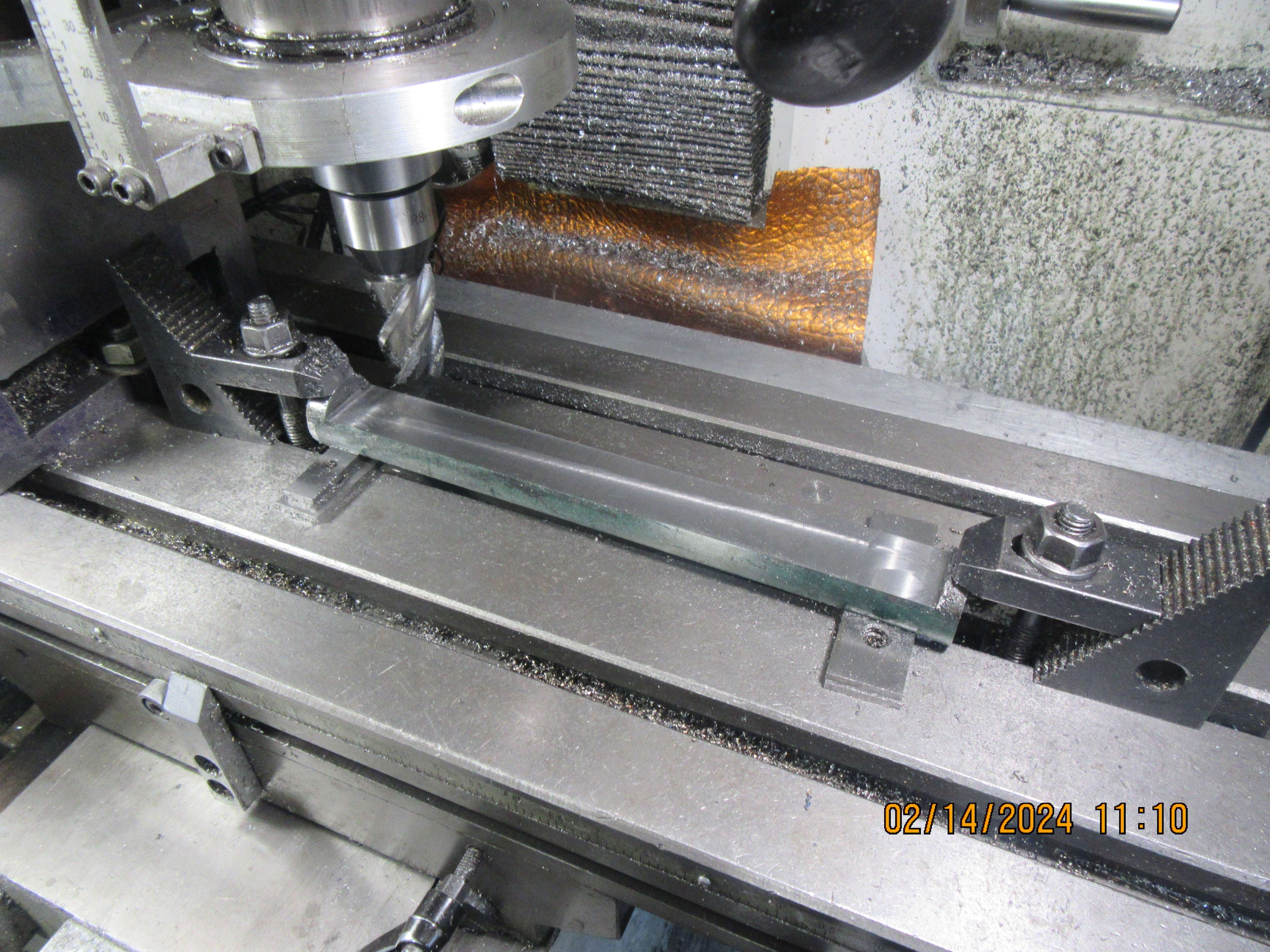
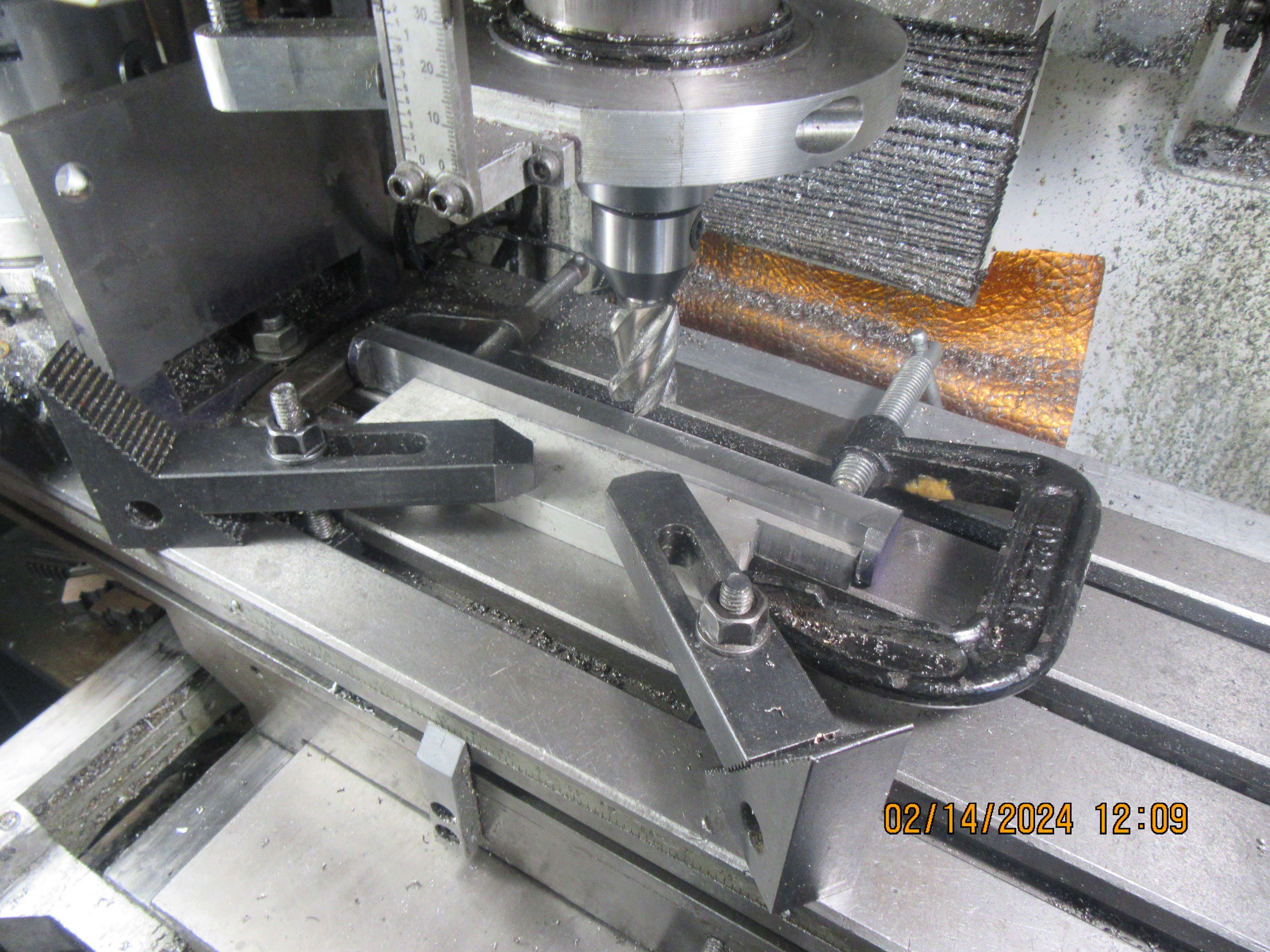
Thanks Brian. I haven't done such a machining operation. So interesting to note your set-up. I should have clamped centrally with narrow clamps, then milled either side... Bowing would have become progressively worse as the material became thinner in the middle. So I guess you have a better set-up? But I do not know how much thicker it would be in the middle than the end under bowing from the tool pressure, doing it "my way"? As the finished crank is machined for main bearings and big-end bearings, I guess that maybe a couple of thou of thicker-in-the-middle isn't a big issue here, but could be on other components? (Unlike the extra 6 inches of thickness in the middle of my body, for example!). I just like to machine as much as possible in a single set-up. Milling the sides in a single set-up should enable the geometry of the machine to give parallel sides?
More than one way to kill a pig, but some are better than others... I am glad to learn from you....
Thanks!
K2
 
Brian, you could reduuce the length now which will mean a shorter distance between ctrs on the lathe so less flex and/or chatter risk.

Machine to desired length and put in the ctr holes, turn the crank pin and all details inside the webs. Then saw the end throws off but make the saw cut ALONG the axis of the crank not across it.

Big advantage is you retain the two ctr holes for the main shaft should they be needed

cuts.JPG
 
Now the round stock has been flattened on both sides. When I flattened the first side, I just laid the piece in one of the grooves in my mill table. To do this second cut, I slid a set of parallels under each end for the previously cut flat to lay against. This ensures that my two opposite sides are parallel to each other.
BZDfr0.jpg
 
The crankshaft has one more flat edge, so a third set-up in the vertical mill is required to make certain that the third flat side is perfectly perpendicular to the other two sides.
cWmAQ7.jpg
 

Latest posts

Back
Top