Sideshaft i.c. Horizontal engine

Home Model Engine Machinist Forum

Help Support Home Model Engine Machinist Forum:

This site may earn a commission from merchant affiliate links, including eBay, Amazon, and others.
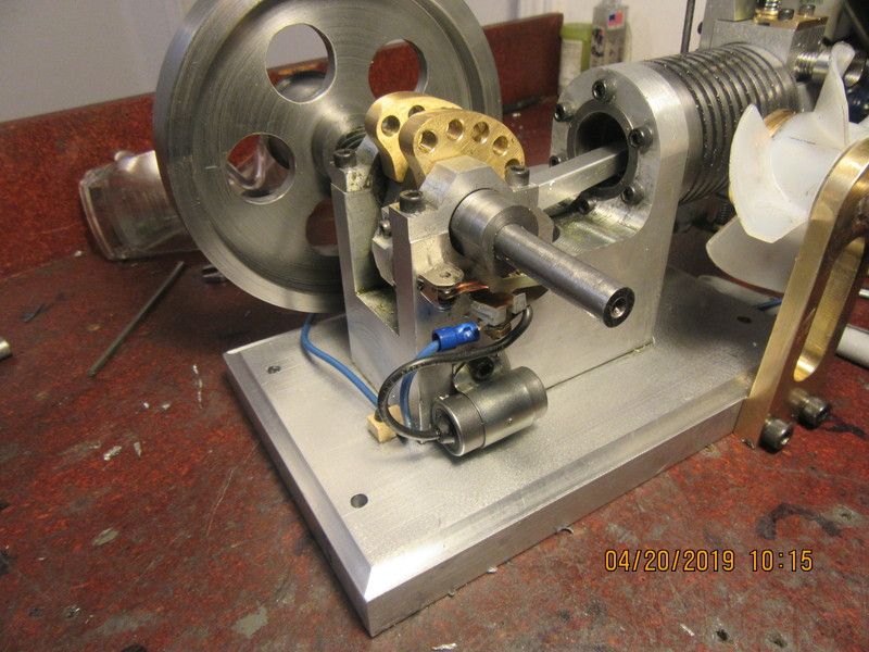
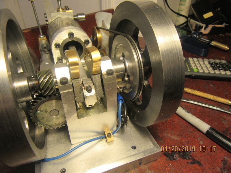
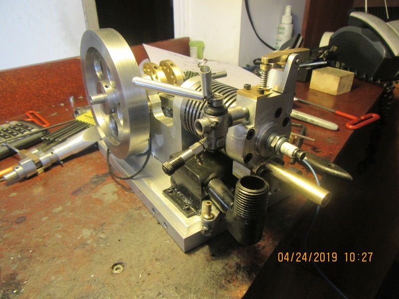
Of course, like all my i.c. engines, I have to have a starter hub. This hub will bolt to the face of the flywheel. Since the crankshaft is relatively small on this end (0.3150") I want to keep any torque forces from outside to be as close to the supporting crankshaft bearing as possible. I will probably make this up today. Also you will see at the far end of the engine a red wire clamp. I don't have it correctly positioned yet, but it is there to hold the "hot wire" which goes to the ignition points so that it doesn't rub on the flywheel and short out.
aDtB6C.jpg
 
There!! That's enough playing for today. Now, if I ever get my crankshaft keyways cut, I have something to engage with my variable speed drill to try and start this thing. At the last minute I decided to put a small flange on the outer edge of my starter hub. If I want to use the starter hub as a power take off pulley the flange will help keep a belt in place.
gfEP6l.jpg
 
Every engine running old school ignition points need a condenser to keep the points from arcing and burning out. Its especially good karma when you get to hide everything in behind the flywheel.--It doesn't always happen that way.
EbcVj5.jpg

gUPaOe.jpg
 
In order to have something to pass today, I set the valve timing and ignition timing this morning. Ringo had suggested that a pneumatic fitting that would screw into the sparkplug hole would be a good way to check for leaking valves before even trying to start the engine. What a great idea. I made one for my earlier hit and miss sideshaft engine, and this one has the same C6 sparkplug, so I thought I'd put some air on the fitting and see what was up with this engine. The exhaust valve didn't leak at all. The intake however leaked like a sieve. I pulled the cylinder head, relapped the intake with 600 grit aluminum oxide paste, then reassembled everything.--It still leaked like a sieve. Tore it down again and relapped the intake, first with 320 grit, then after a laquer thinner cleanup I lapped it again with 400 grit. Then after a second cleanup, I lapped it again with 600 grit. That fixed it. I'm getting a definite "bounce back" now when I spin the flywheels by hand.
 
Its time to think about a gas tank. Space is really at a premium here, and I don't want a big external tank to mess up the lines of the engine. The tank I have shown in pale green utilizes the last bit of free space and still leaves clearance between the top of the tank and the underside of the cylinder, so as not to interrupt the breeze coming off the fan. The outside dimensions of the tank are 2" x 1 1/2" x 2 1/2" long. This will hold quite a lot of gas, and the main part of the body can be built from a section of 2" x 1 1/2" rectangular tubing with endplates welded into it. You will also note that I have used a Traxxas Pro 15 carburetor--Not because it is better than a home built one, but because it will be quicker to get a running engine than taking the time to build another carburetor right now.
JHj2di.jpg
 
I scratched and scraped around in my "stuff you should never throw away" drawer and found a piece of 2" x 2" x 3/16" square tube and some oddments of 1/8" plate. The bandsaw cut one side off the square tube and yielded a 2" x 1 1/2" channel which will become the top and two sides of the tank. The three pieces of plate in the picture will become the bottom and two endplates for the tank. A gas tank could be made from much lighter material, but this stuff is FREE!!! When it's all welded together and painted, nobody will know. Jury is still out on the filler neck and cap.--And Oh yes--If you look under the cylinder you will see a block of wood cut to the size the finished gas tank will be. I really didn't want to make a tank that wouldn't fit after I got it finished.

PuEc1z.jpg
 
Don't laugh!! This is the very latest in "blow your guts out leaktesting". The pail of water is out in my main garage. Works great.--Submerge gastank in pail of water. Put brass fitting in mouth. Blow your guts out and look for bubbles. Keep resoldering until there are no more bubbles. The neoprene tubing, pipe plug, and coupling all unscrew from the gas tank filler pipe. At the moment, the gas tank has no leaks. After sanding and cleaning it up ready for paint, it is my sincerest hope that no more leaks are found. The outfeed to the carburetor is going to be a bolt on affair. The mousetrap is not part of this apparatus. Caught one mouse in the pantry last night, and placing the trap on my side table is good wifes subtle reminder to set it again tonight.
wAD2o1.jpg
 
And a lovely thing it is, indeed!! It fits into the space that was available, it doesn't foul the blades of the cooling fan, and that rather ridiculous long filler spout neck coming out of the tank at a 10 degree angle ends up in the correct spot. Far enough away from the sparkplug to prevent arcing to it, and convenient to fill.
wmzIig.jpg
 
Nothing too outrageous today, but progress none the less. I made up the aluminum fixture which bolts to the side of the gas tank. This piece bolts to the side of the gas tank and the actual fuel passage is sealed with a rubber o-ring between the gas tank body and this aluminum part. The gas tank is threaded for the bolts, and the bolts will be coated with J.B. Weld as a sealing agent. I did fabricate and install an anti flowback valve, same as on the sideshaft hit and miss engine, with a 3/32" diameter ball. I was able to drill and tap two of these holes in the gas tank with my existing tooling, but had to order an extra long drill and #4-40 tap to get the other two which fall directly under the long filler spout. The goopy looking stuff is J.B.Weld which has to dry 24 hours before I do much clean-up on it.
yb9E6d.jpg
 
The gas tank has been mounted to the base. Taking a picture of this is about the same as taking a picture of a black cat in a coal bin, but you can see enough of what I'm doing. This was one of the times where I didn't want to put the holes in the baseplate before hand. A fabrication like the gas tank might have the bolt holes exactly where you want them on cad, but there is more of a chance that they won't be. This was an opportunity to set the finished gas tank in place and mark thru with transfer punches. I have only one extra length drill, and fortunately it was smaller in diameter than the #5-40 thread tap drill. So--set the tank up, transfer punch holes, use my one and only extra length drill to drill thru the base, then set the base on its side in the mill vice and drill thru from the other side with the correct size tap drill, then tap from the wrong side (thankfully my taps were just long enough to go thru the 3/4" baseplate), then tear down the setup and put the bolts in place. Fortunately I didn't have to remove the cylinder to do any of this, but I did have to dismount the sideshaft housing.
p24MxF.jpg

jLKN5F.jpg
 
Bob--I use a tool designed by George Britnel to cut my valve seats, and it is an absolute lifesaver. I will hunt down my drawing and a picture of it to post here. It is the best tool I have ever used to ensure leakproof engine valves, and I bless George Britnel every time I use it. I always make "valve cages" which combine the valve guide and the valve seat in one piece, and the Britnel tool ensures concentricity between valve guide and valve seat. It is a tool which is used by hand, never under power. I generally use only 600 grit valve grinding paste, and if a valve isn't sealing properly for any reason I will lap it with 400 grit, then 320 grit, and finish up with 600 grit.
nzgeZg.jpg

f5O91o.jpg

KZVG9B.jpg
 
Last edited:
And here we have a typical detail of a valve and an assembled "valve module". The concept of making up a "valve module" complete, and then pressing it into the cylinder head is something brand new for me. Normally the valve cages are pressed and Loctited into the cylinder head first, and then after they are in place the side port is drilled thru the cylinder and the valve cage all in one step, and then the Britnell tool is used, and then the valve and keeper and spring are assembled after the fact. Don't let the "pressed into place" fool you. If it is a hard press, the cages distort. If the cages fit loosely they will leak. It should be a "hard finger press" and God help you to achieve that. It takes skill and practice to get that fit. If you do turn the cage SLIGHTLY UNDERSIZE you can sometimes save them by knurling the o.d. of the cage. Knurling will actually make the o.d. "grow" by a few thou.
LzSyCj.jpg

6dZfHC.jpg
 
Sing Hallelujah brutha--My new broach finally came. During the past week while I've been waiting for the new broach to show up here, I have went ahead and finished all of the little things that I normally might not have done until the flywheels were broached and the engine test fired. So--Tomorrow may be the day!!!
Vih6Bf.jpg
 
Last edited:

Latest posts

Back
Top