Do you drill the holes on an XY table or a rotary table? I'm assuming you did those on the mill and not on a drill press.
You are using an out of date browser. It may not display this or other websites correctly.
You should upgrade or use an alternative browser.
You should upgrade or use an alternative browser.
Sideshaft i.c. Horizontal engine
- Thread starter Brian Rupnow
- Start date

Help Support Home Model Engine Machinist Forum:
This site may earn a commission from merchant affiliate
links, including eBay, Amazon, and others.
Use the x-y table on my mill for that stuff.
JohnBDownunder
Well-Known Member
- Joined
- Mar 1, 2012
- Messages
- 109
- Reaction score
- 28
Another project to keep watching.
Thanks Brian for posting.
I for one will be following with interest cos I learn stuff that hopefully I shall remember when I need it.
John B
Thanks Brian for posting.
I for one will be following with interest cos I learn stuff that hopefully I shall remember when I need it.
John B
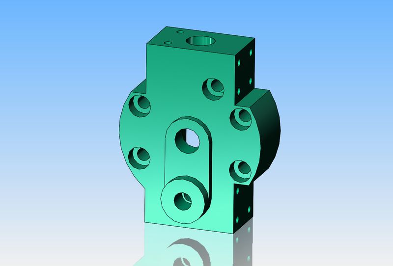
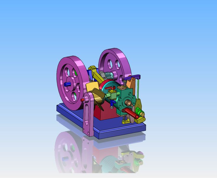
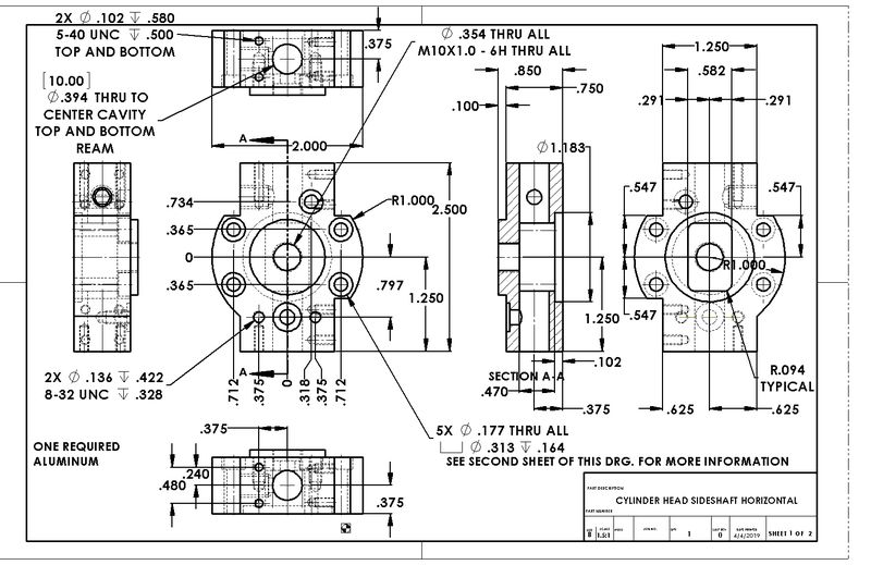
All the things I have done so far are just repeats of parts and operations that I have done many times before. The exciting part for me is about to begin, up at the cylinder head end. I have actually made the rocker arm and exhaust valve and sideshaft cam on my previous sideshaft hit and miss engine, so that's not entirely new either. The overhead intake valve and rocker mechanism will be "sorta/kinda" new to me. I am not going to commit at this time about the position of the fuel tank. There is room enough to squeeze one under the cylinder, but after all the issues I had with my previous engine has made me a bit leery of fuel tank positions. The cylinder head, although not terribly complex, is going to be "interesting". It can be made from a length of 2" x 1" aluminum bar.

Last edited:
I've been setting here studying the two raised bosses on the face of the cylinder head in the above picture. They look nice, and they both serve a function. I'm just not 100% sure that I can make them. If I made them rectangular they would still function, but it wouldn't look nearly as nice. But--if I make them rectangular, I can set the part up on my mill table and use the boring head with a reversed boring tool and round the perfectly circular boss down to the surface of the longer raised portion.--Then how do I get the corners rounded on the longer raised portion?

Last edited:
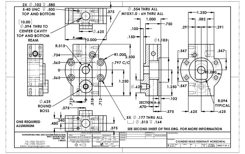
Okay--Minor design change here. That round boss was only there to give enough material to screw in an exhaust pipe. I have removed the boss completely and went to a flange mounted exhaust pipe. This lets me change the other long boss to be circular, which gives me sufficient thickness to screw the sparkplug into and makes machining a lot easier. Now it can be done on the lathe with my four jaw chuck.
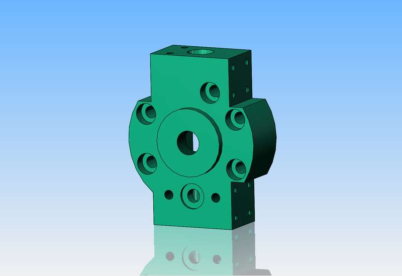


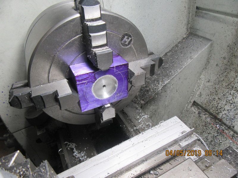
The block which will become the cylinder head has been machined to correct overall dimensions. It is set up in the four jaw chuck, and the first cavity machined into one side. This is the side which fits against the cylinder, so the recess just formed fits over a register turned on the end of the cylinder. While it is still in this set-up, I have drilled a 3/16" hole thru, so that when I flip it over to machine the far side I can pick up exactly the same center. eventually that 3/16" hole will be opened up to accept a sparkplug with a 10mm thread on it.

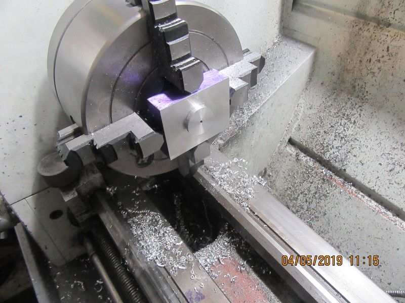
Part has been flipped over in the four jaw, and machined so as to leave the boss which the sparkplug fits up against. This is the last "on center" work that I have to do, so before I tear down this set-up I will drill and tap the sparkplug hole.

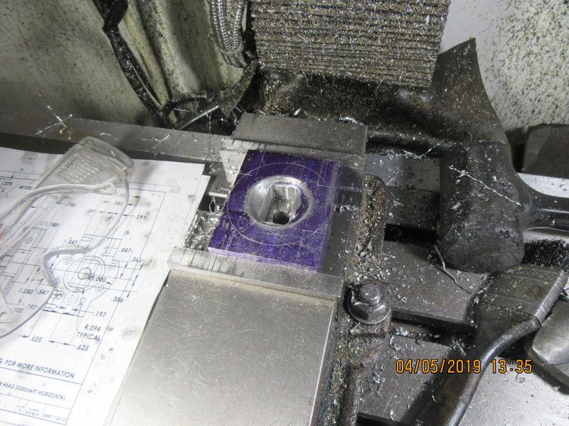
The burn chamber has been milled. My gimpy back is starting to talk to me, so I'll finish this cylinder head off tomorrow.

Jeez--I may have to rebrand this engine as the "Cyclops".
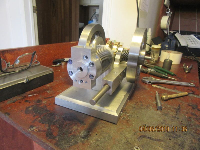

I kind of got the cart ahead of the horse here. I really should have built the piston next, but I was so intrigued by the shape of the cylinder head that I had to make it first. I will probably make the piston tomorrow.---Brian
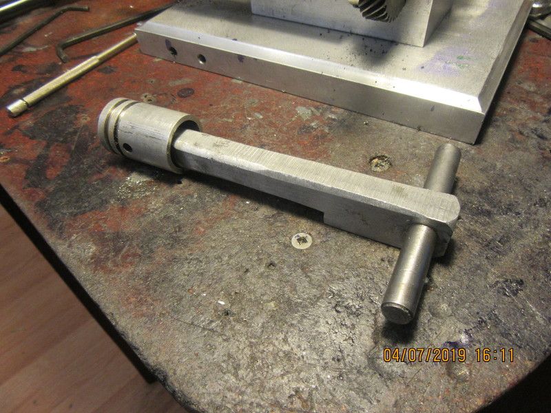
Todays offering to the machining Gods is a big beautiful cast iron piston. It was machined to about .001" larger than the bore of the cast iron cylinder, then "wrung" into the cylinder with 600 grit aluminum oxide paste. The cylinder bore was honed with a 3 stone brake hone, but not lapped. It is self lapping when "wringing" the piston into the bore with aluminum oxide paste. The piston pin is a bit of 3/16" cold rolled steel, held in place by a set screw in the piston.
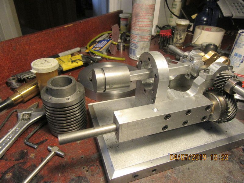

The idea of "wringing" a piston into a cylinder works like this. . The theory is that you turn the piston to be about .0005" to.001" oversize. Then using a loop of 220 grit sanding strip, work it back and forth on the piston until the piston just begins to fit into the cylinder, but not go in all the way. At that point the cylinder is held in the chuck, and the piston is mounted on a T handle and coated with 600 grit. With the lathe on its slowest speed, you hold the T handle and work the piston in and out. This is scary as hell, and you have to be ready to instantly let go of the T handle if it grabs. Each time you try to move the piston into the cylinder, it will go in a little farther, as the grit wears away some of the piston o.d. and some of the cylinder i.d. You keep working it until the piston will pass completely through the cylinder. What you end up with is for all intents and purposes a zero clearance between the piston and cylinder. The hardest part of this procedure (other than the fear of getting wrapped up in your lathe) is turning the piston to the correct diameter. If you leave the piston too large, it grabs, jerks the tee handle out of your hands, and makes you crap your drawers. If you take off a thou too much, then you have no material to "wring" away.

Last edited:
Almost all of the small semi-diesel model airplane engines are made this way with no rings at all. They rev so high that compression doesn't have time to leak down around the piston. I can run my engines without a ring when they are made this way, but I have found that for really slow running engines that they work better with one Viton ring.
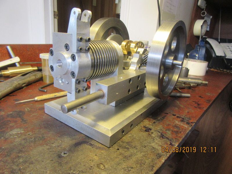
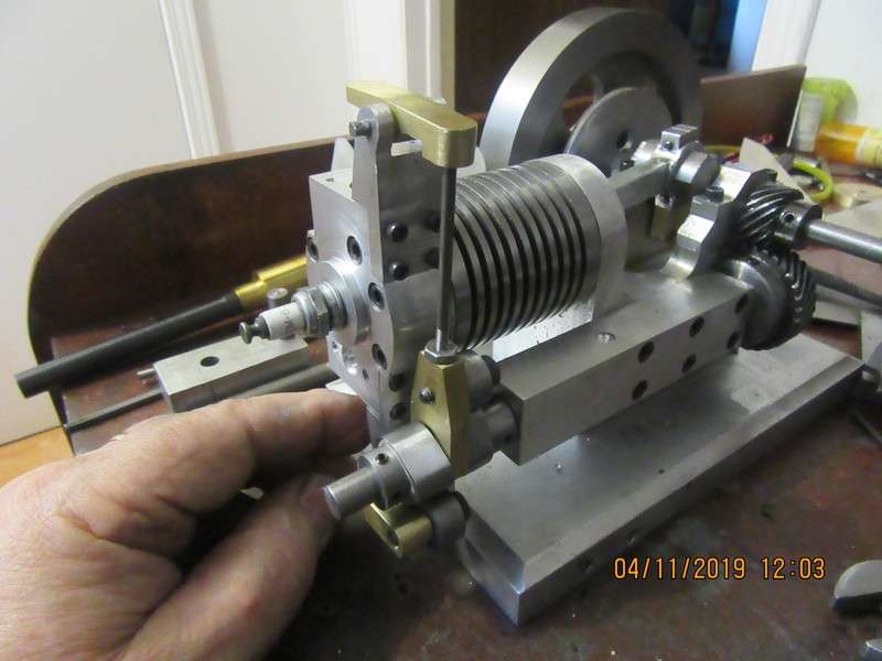
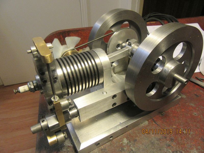
Today the magic beast has grown a set of antlers---well, not really. Those are the pivot towers for my inlet and exhaust valve rocker arms.

- Joined
- Sep 2, 2011
- Messages
- 1,342
- Reaction score
- 360
those horns do make it look mean... its looking good Brian.
I was just doing some research on recommended valve lift for the cam design on this engine. I found a site that recommended that valve lift should be roughly equal to 12% of the cylinder bore on a 4 cycle engine. This engine has a 1" bore, so it seems that a total valve lift of 1/8" (0.125") should be about right. This is not cast in stone, since I can design cam lobes to give whatever lift I want. This engine will be a slow revving engine. I would appreciate input from other model engineers on this. I know that on my model hit and miss engines with atmospheric intake valves that the exhaust valve lift is almost 0.170", while the valve lift on my 1" bore flathead engine that was featured in The Home Shop Machinist magazine is only 0.080".
Today was rocker arm day. They are brass, which will look nice with a bit of polishing. The size of these little things in no way reflect the amount of work that goes into making them!!!
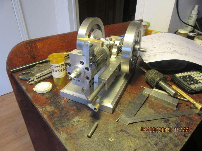

Lots of little fiddly bits done today. The cam contact rollers and fork, and the fan bracket. I hope to make both cams tomorrow.
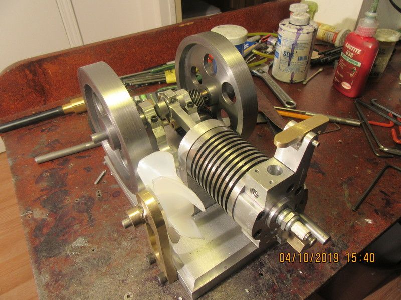
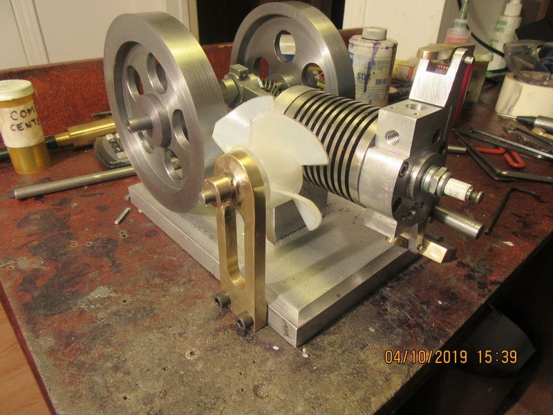
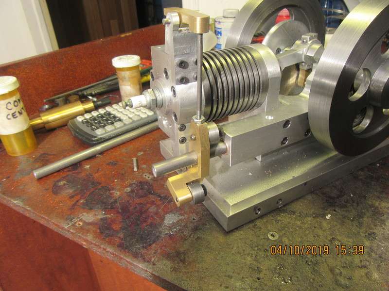


The cams came out without any problems. They are simple flat sided cams and were very easy to machine. I had far more trouble and fussing with that brass pulley at the fan. I have to quit and figure out what comes next. I think I'm down to the valve/valve housings. They will be made as sub assemblies, then inserted into the cylinder head like I did on the previous hit and miss engine.


Similar threads
- Replies
- 148
- Views
- 21K
- Replies
- 19
- Views
- 5K
- Replies
- 356
- Views
- 54K
- Replies
- 42
- Views
- 11K


