Sideshaft i.c. Horizontal engine

Home Model Engine Machinist Forum

Help Support Home Model Engine Machinist Forum:

This site may earn a commission from merchant affiliate links, including eBay, Amazon, and others.

Brian Rupnow

Design Engineer
Project of the Month Winner
Joined
May 23, 2008
Messages
14,886
Reaction score
8,213
Location
Barrie, Ontario, Canada
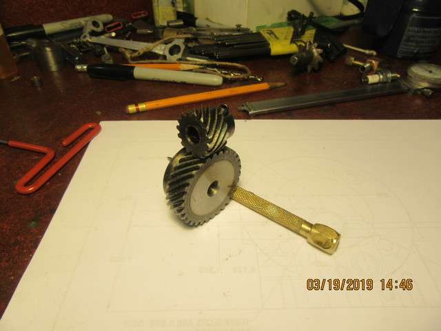
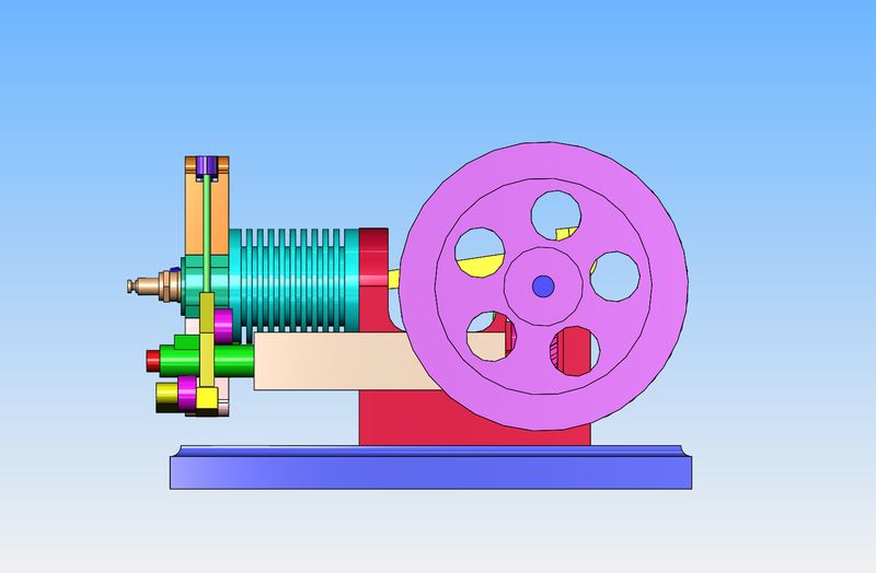
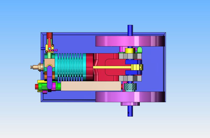
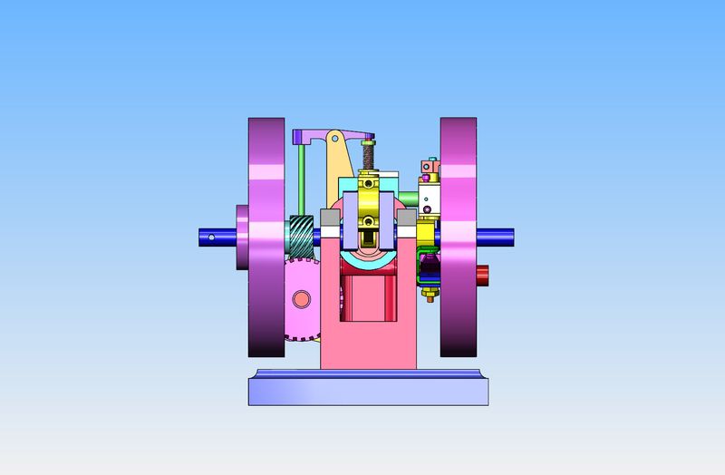
You fellows may remember---When I was chasing down helical gears for the sideshaft hit and miss engine I built, I bought a pair with 2:1 ratio off Ebay for $12.00 which is about $90 less than I paid for a set made in USA. I used the made in USA gears from Debolt to build my engine, but had the Ebay Chinese gears left over. I watched a YouTube video of an Edgar Westbury engine called the "Centaur" and was very impressed with the valve and sideshaft arrangement on it. Grandma was right--Idle hands truly are the devil's workshop. I was bored this week, so I've been messing around designing another sideshaft engine which uses the Chinese helical gears, and a valve arrangement similar to the Centaur engine. It's not a hit and miss engine--just a 4 cycle open crankshaft engine with a throttled carburetor. I might never build it, but it is interesting.
r3XqOf.jpg

BQPlp8.jpg

Sp7ffe.jpg
 
The engine has a 1" bore and a 1.375" stroke and is air cooled. I will probably design a fan on the side opposite from the sideshaft and drive it with an o-ring drive belt from the crankshaft.
SdFOP2.jpg

aGYvHM.jpg
 
Werowance--Yes there will be a cam for the exhaust and also a cam to operate the intake. The intake will no longer be "atmospheric". A valve is considered as "atmospheric" only when it depends on atmospheric pressure to open it.---Brian
 
Of course, if you have an air cooled cylinder, it's always a good idea to have a cooling fan. I dug around in my "odds and ends" drawer and found the perfect size plastic fan. I also dug around in my aluminum box and found a scrap of 2" aluminum large enough to make the main engine body from, and a piece of 3/4" material large enough to make a base. I spent a couple of hours this morning putting in all of the tapped holes and clearance holes to put this thing together.
9piB8E.jpg

d48nRI.jpg
 
I've just done one of those things that drive machinists crazy. This main chassis for the engine is up on my mill right now, and I've just realized something about the counterbores for the ball bearings. The counterbores won't be put in until the bearing caps are made up and bolted into place. I don't see any way to machine it like this. I can open the hole to full size on one side and then fit the boring bar down thru it to counterbore the other side, but unless I'm missing something I can't put a counterbore in both sides. Its not critical that it have the web left in the side of the hole to back up the ball bearing, but it would have been nice. I know I could resort to some old time voodoo and mount it to the lathe saddle and make up a boring bar that gets assembled in place to do the counterbores, but I prefer not to do that.
J5B3LJ.jpg
 
How about something like these back spotfacers from Travers.

https://www.travers.com/high-speed-steel-reverse-spotfacers-bayonet-lock-pilot-arbors/p/108779/?lite=true&pricelistname=SITE&keyword=backspotfacers&hawkdym=back spotfacer&hawks=1

I was actually looking for the kind of counterbore tool that has a single shaft/shank, and various cutter heads slip onto the shank. In your application, the bare shank would go in thru one side first, and then the cutter would be installed on the shank to do the back work on the other bearing saddle. They might be cheaper and sturdier than the back spot facers.

P.S. And all this because you had a couple of cheap right angle helical gears left over? Somethings not right, but I understand, LOL.

I have use a system like this but with a countersink on a 1/8 mandrel. Worked great
Gary.
 
That didn't go too badly at all. I have a multitude of holes to tap, and I'm still thinking about the counterbore issue, but I like the way the piece turned out. About 90% of it was "Lay out the shape on a piece of 2" material, bandsaw close to the line, then mill to the line". Tomorrow I will think some more about the counterbores and tap all the holes.
QQ0UoI.jpg

J8vZoP.jpg

cnDVpJ.jpg
 
I've figured out the counterbore. I can do both sides with a brazed carbide boring tool in my boring head. The crankshaft is 3/8" diameter. The clearance hole around the shaft is going to get opened out to 5/8" diameter. The counterbore for the bearing is 0.906" diameter. The shank on the brazed carbide boring tool is .425" diameter. The only part that of this that sucks a bit is that I can't do both sides in one set-up. I have a 5/8" reamer which will be used to put the clearance hole thru all. That way I can "pick up" on the reamed hole when I flip the part over to do the other side.
 
Todays work involved tapping all the holes I had drilled yesterday in the main chassis and fabricating a pair of bearing caps. Those bearing caps have a lot more work in them than you would think at a casual glance. Why is the half hole in the bearing caps a different size than the half hole in the main frame?--That comes from making changes on the fly and not writing them down on the drawing as I do them. It doesn't really matter. They are clearance holes around the crankshaft and still have to be drilled out to a larger size before things are finished. Tomorrow I will tackle the bores and counterbores. Every fifteen minutes I have a different plan on how I'm going to do it--Probably won't know myself until I'm actually doing it.
wjJWyb.jpg
 
So--Here we have the main chassis and baseplate set up in the milling vice. The top hole has been drilled thru and reamed to 0.750". The bottom hole (which will be on the sideshaft side of the engine) has been drilled and reamed to 0.4375" diameter. The boring tool fits down thru the .750" clearance hole and has counterbored a 0.906" diameter hole x 0.312" deep into the inside face, to hold the ball bearing.
VyOVd4.jpg

JO2y4L.jpg
 
I'm not really sure of what it is I'm doing, but that has never stopped me before. To put the counterbore in the other side of the engine chassis, I need some kind of "setting master" to set the boring tool to the diameter I require. I don't have any practical way to do that when the boring tool is in the part, so I will do it in the lathe. I have just turned a "setting master" from mild steel, one end of which is bored to the size required for the bearing and the other end turned to be about 0.010" smaller than the 7/16" hole which the boring tool must pass thru. It will become clearer as I post more pictures.---I hope!!
nLVNte.jpg
 
So--Here we have me setting the boring bar (held in the headstock chuck) to the inside diameter of the "setting master" which is held in the tailstock chuck. Also a picture of the counterbore cut into the second side of the engine chassis. It worked out perfectly.
SD3uU5.jpg

qnNoQ0.jpg
 
And last but not least, the two sealed ball bearings at home in their counterbores. You will note that the non sideshaft side has a much larger clearance hole than the sideshaft side. That is because with the large clearance hole cut into the side of the chassis for one of the helical gears, I didn't want to take any more material away than I absolutely had to.
P4rU2s.jpg

UiSd7h.jpg
 

Latest posts

Back
Top