Design and build side-shaft hit and miss engine from bar stock

Home Model Engine Machinist Forum

Help Support Home Model Engine Machinist Forum:

This site may earn a commission from merchant affiliate links, including eBay, Amazon, and others.
I realize you are probably aiming for a simpler engine but maybe you could watch some videos on Otto slide-valve engines or maybe some on cam stop engines. Little more challenge.

Cool little video I watched lately. Nice vertical side shaft engine at 2:34.
 
This is an interesting model. I have remodelled the sideshaft governor to the correct size, and just for the heck of it positioned it in the approximate place it would go on the "Odds and Ends" hit and miss engine. The "odds and ends" engine has a 1" bore and 1 3/8" stroke, same as the sideshaft engine I will be designing. The side-shaft engine flywheels will be 6" diameter instead of the 5" on the Odds and ends engine, but all in all its fairly close to the same size. The governor doesn't "overwhelm" the engine visually.
S3e72R.jpg
 
Barnbikes--I've watched a hundred videos of side shaft engines in the past two weeks. There is an amazing lot of information on the web, if you can ferret it out.---Brian
 
Since I don't have my gears yet, the only part of the engine available to work on is the governor, which I now have modelled to scale. Nice rotary table work doing the very top part. I'm having a devil of a time to get a good picture. With shop lights off, its too dark, but not dark enough for the flash to work. With both spotlights focused on the part it all washes out. This is the third try with my camera.
nJRgNJ.jpg
 
This morning I made up a pair of filing buttons. If you have heard of filing buttons and weren't sure what they are---I have to file a nice radius on both ends of the governor top. If it was a big piece, I would free-hand it on my big stationary belt sander. Being such a small piece, I wouldn't be able to do that and have it come out looking right. So--filing buttons are made up from 01 steel, having the correct outer diameter and center hole and flame hardened. They are assembled as you see in the picture with a piece of the correct diameter shaft (.093" in this case.) Now when I file the radii on the aluminum governor cap, the hardened filing buttons will stop me from cutting too deep with my file and ending up with wonky looking radii on the aluminum part.
xpLE94.jpg
 
And here we have the finished governor top. You can see the radius that is filed on both ends, where the cross holes are. It isn't perfect, but it's light-years beyond what I could have done freehand. I have a tin can where I keep all of my filing buttons as I make them. They can be used again and again without damage, because they are very very hard after the flame heat treatment.
O4hSND.jpg
 
The brass governor parts are very small, way smaller than my comfort level. I chose to make my governor weights from pieces that are machined, then silver soldered together. This of course required me to make a "one time use" welding fixture to position the parts for silver soldering. After the soldering is done, I may have to cut it apart to free the components, that is why it is a "one time use' jig. The solid brass ring will be cut into four pieces, two of which are silver soldered to the "pivot ears" and two which will become scrap.
y5JwRX.jpg

lQu2Xs.jpg
 
As I suspected, the welding fixture had to be cut away after the silver soldering was completed. This was not really a matter of the solder sticking to the aluminum welding fixture. It's just that the brass pieces were a very close tolerance fit into the aluminum fixture. When I make an aluminum fixture like that, about half the time parts of the aluminum melt while the silver solder is being applied. It doesn't bond to the brass, but it manages to mechanically lock to the brass weldment. It cut away very cleanly and the soldered joints came out looking very good.
fEBcGf.jpg

DaEXzB.jpg
 
Not quite there yet, but getting darned close. Both of my bevel gears came in, still waiting for helical gears. I have a bunch of "real" work calling me so probably won't post anymore of this today.---Brian
0ueiQP.jpg
 
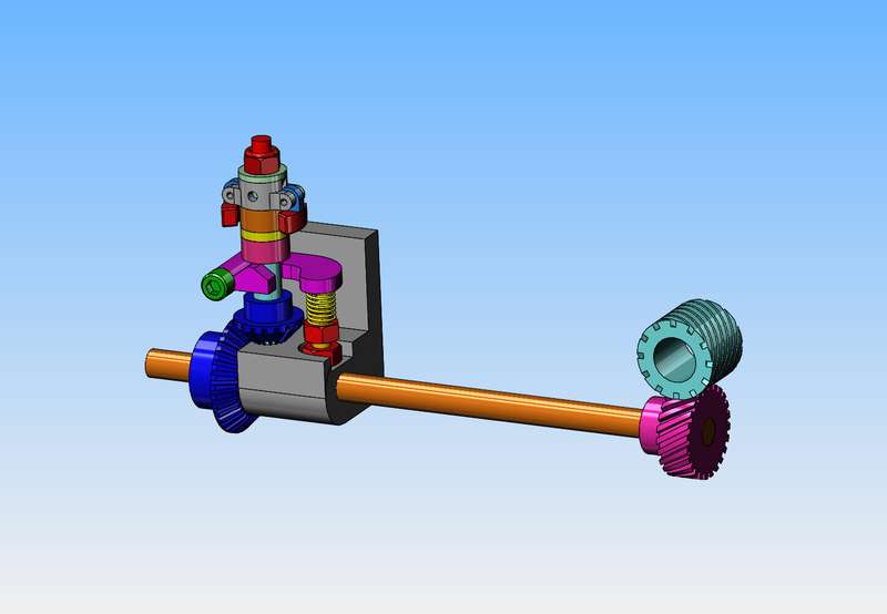
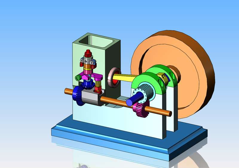
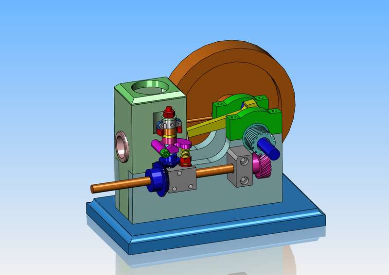
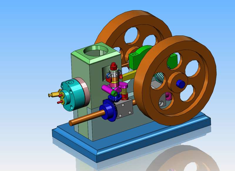
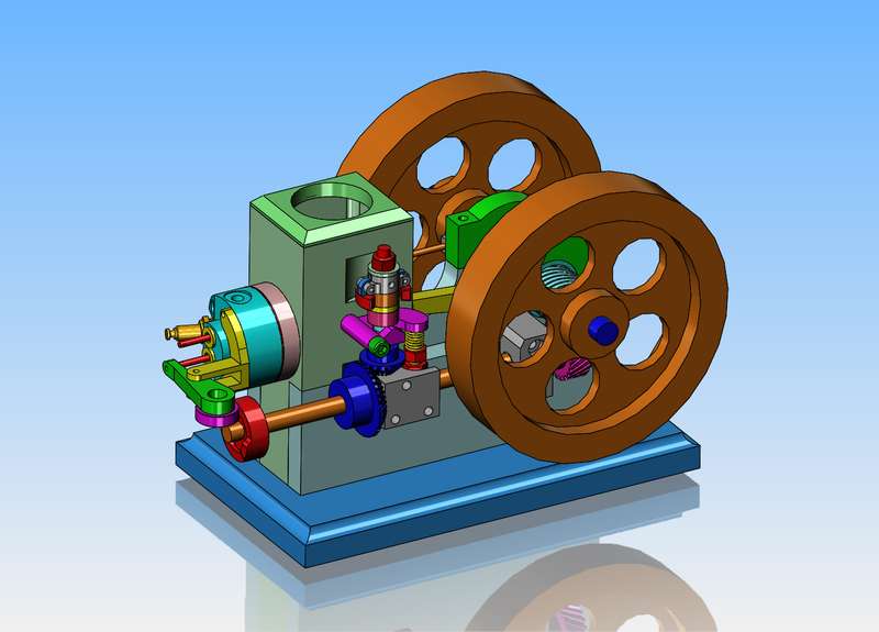
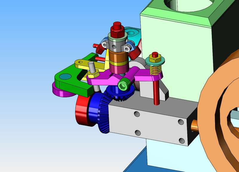
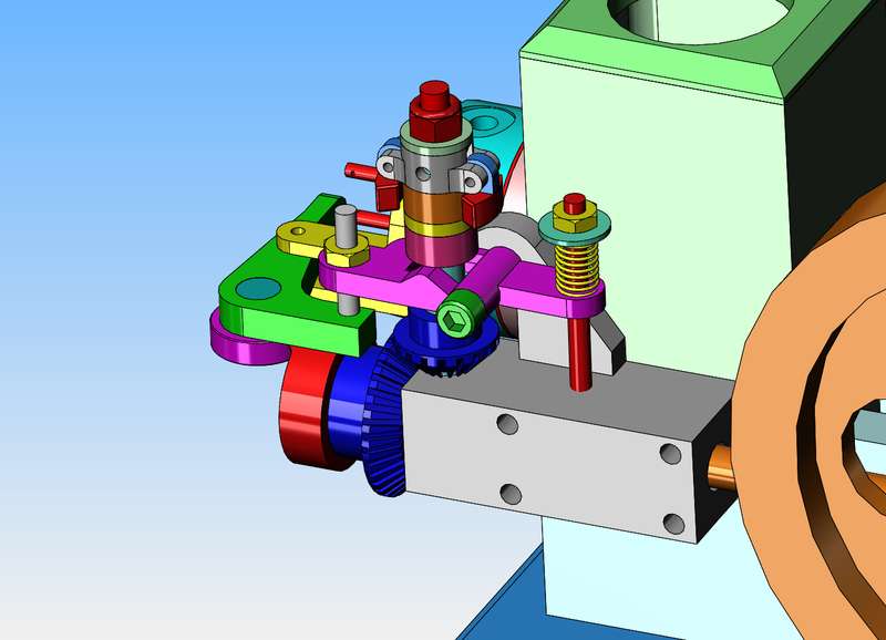
Brian - As you're a fan of unusual mechanical designs I thought I'd mention something I came across today that I've never seen, possibly so you can file it away in the memory banks for future usage if you desire. Basically, it was a 'normal' horizontal engine, with a normally operated exhaust valve. However, instead of an atmospheric intake valve, it was cam actuated. All pretty standard stuff, except the same 'pushrod' operated both intake and exhaust valves. The exhaust used a rocker arm but the pushrod had another arm attached to it and simply pulled down on the intake to activate it. I couldn't see it but the cam must have had both a peak for the exhaust and a 'valley' for the intake, along with a central nominal diameter. Plus the pushrod (push-pull rod?) had to have some sort of spring keeping it in contact with the cam and strong enough to overcome the intake spring force. It's not an engine I can see running currently but I imagine it's an interesting motion that would scale fairly easily.
 
My helical gears from Debolt showed up in the mail today, and I am very impressed. They look like good quality gears. The one which has an extended hub on one side will get a couple of set screws drilled and tapped thru the extended hub to hold it to the camshaft. I'm not exactly sure how to attach the other gear to the crankshaft at this point. I also stopped by my metal supplier guy today and picked up two 1" long cuts from a hotrolled 6" diameter mild steel bar for $25.00. In the background of the helical gears you can see the two 1/2" ball bearings that will support the crankshaft. The seals will be removed and the grease washed out, then a bit of light oil applied to them.
KLp4m1.jpg

dIA3DK.jpg
 
Well, it can't really be this easy but here it is with one flywheel hidden. 1" bore and 1 3/8" stroke with 6" diameter flywheels. The devil is in the details, and I haven't even thought too much about the cylinder head and cam yet, but I think it's kind of cute.
4Oecwz.jpg
 
Brian,
I always enjoy your posts / machining adventures, and I learn heaps.
In post #24 you mentioned having trouble lighting the photograph (either dark or washed out). A trick I have used in the past is simply put a facial tissue or similar over the flash head to cut the emitted light. Also softens / disperses the flash. Might help another time and maybe worth a try.
John B
 
So, today we got a bit more serious about just how we were going to support the sideshaft, and ended up with two bolt on brackets complete with oilite bronze bushings. Yes, we had to carve a bit out of the side of the waterjacket to give clearance for the flyweights of the governor when they were spinning around. We also carved a bit out of the waterjacket and the sideplate a bit farther down to clear the largest bevel gear. A fancy top was whittled out for the waterjacket, and the tops of those swishy looking bearing caps were modified to something I like better. Everything fits so far. I had to move the sideshaft out away from the centerline of the engine to get the clearances I required. Thats alright though, because the helical crankshaft gear doesn't have to have the helical camshaft gear riding exactly in the center. It can move about 0.100" from center and still have all the teeth engage. The narrow vertical portion of the sideplates below the waterjacket seemed to be a bit skinny, so it got about 5/8" taller and cutout in the waterjacket part got 5/8" taller to accommodate it. I don't yet know just how I am going to secure the cast iron cylinder in the waterjacket, but will probably put a "head" on the end farthest from the crankshaft and a ring of counterbored shcs. to secure the cylinder.
GHXQz1.jpg
 
I'm getting right down to where the bear shat in the buckwheat now. I was originally going to leave the flywheel webs solid, but I didn't like the look, so added some holes. I tried a 1" diameter hole but it didn't look right, so I ended up with 1 1/4" diameter holes. That's all well and good on the computer screen, but the largest drill and end mill I have are only 1" diameter. I rooted thru all of my different cylinder head models, and ended up stealing the cylinder head, head gasket, valve cages, valves, valve springs, and valve retainers from the Rockerblock engine to use on this hit and miss engine. The cylinder head model got reworked a bit, but not a lot. I have to have all of the cylinder head stuff in place before I can start to think too much about the exhaust valve lockout mechanism.
Z7xN07.jpg
 
I've been kind of expecting that this would happen. The length of the valve stem (which has to be this long to allow for a spring and spring retainer) dictates where the rocker arm and pivot should go. The "cam follower bearing" is a bearing I happened to have already, which measures 0.864" diameter. The diameter of the cam follower bearing dictates where the rotary cam has to be. As a consequence of this, the governor will have to move to the left as far as I can take it.--I'll do that tomorrow.
TZWxc7.jpg
 
It has been a very interesting morning, trying to find room for the governor up near the head of the engine.--And it wasn't until I had spent 2 hours moving it up there that I realized the governor works in reverse to what I needed.--So, the governor pivot was moved to the other side of the stem post centerline. This allows the governor to work the way I needed it to. I have attached two pictures--One shows the governor engaged and locking out the exhaust valve by preventing the rocker arm from rocking to close the exhaust valve. The other picture shows the governor disengaged, which allows the rocker arm to rock normally and open and close the exhaust valve.
gcGRYW.jpg

u4TV4B.jpg
 

Latest posts

Back
Top