Whittle Aero V8 WIP

Home Model Engine Machinist Forum

Help Support Home Model Engine Machinist Forum:

This site may earn a commission from merchant affiliate links, including eBay, Amazon, and others.
Thanks Zee for the confidence.

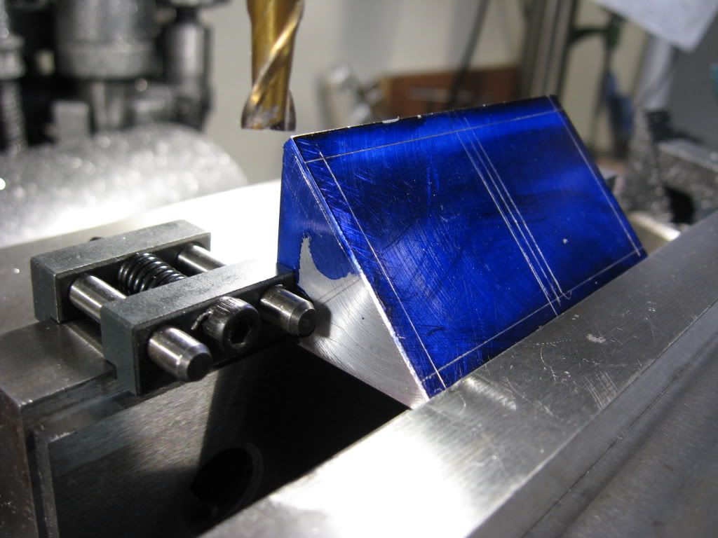
Well very little done tonight besides stare at the prints and scratch my head. I jumped onto the upper crankcase just for a change of pace. 3 lowers and I needed a break. I started the camshaft "hole"

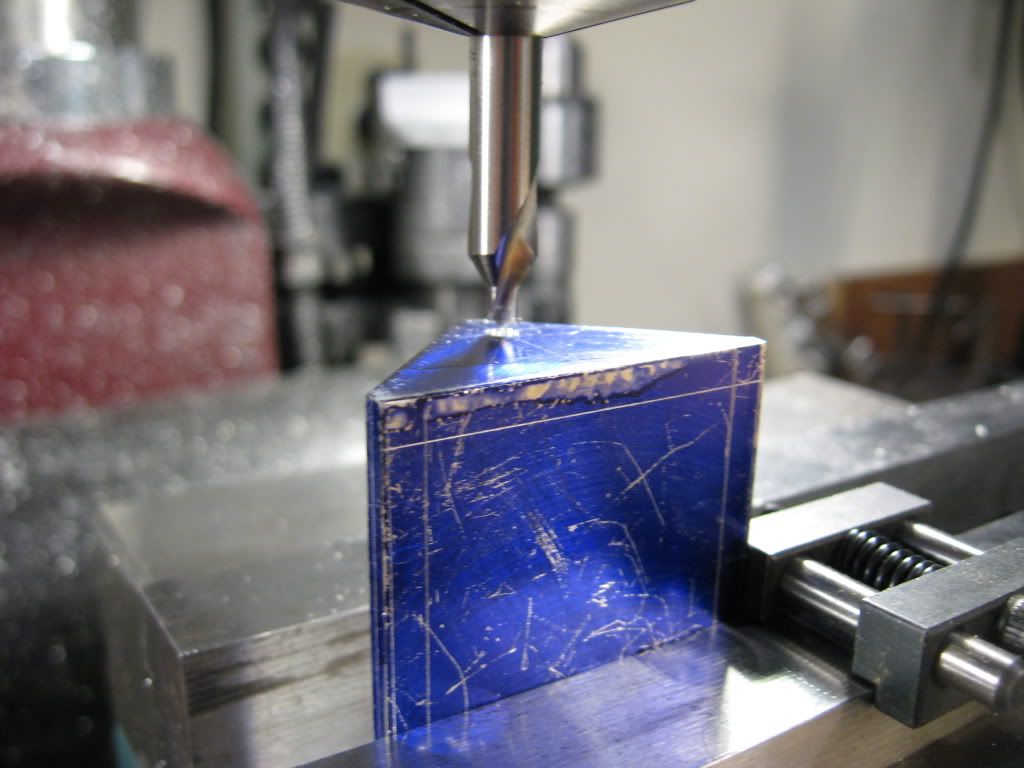
Center drilled the location
IMG_0670.jpg


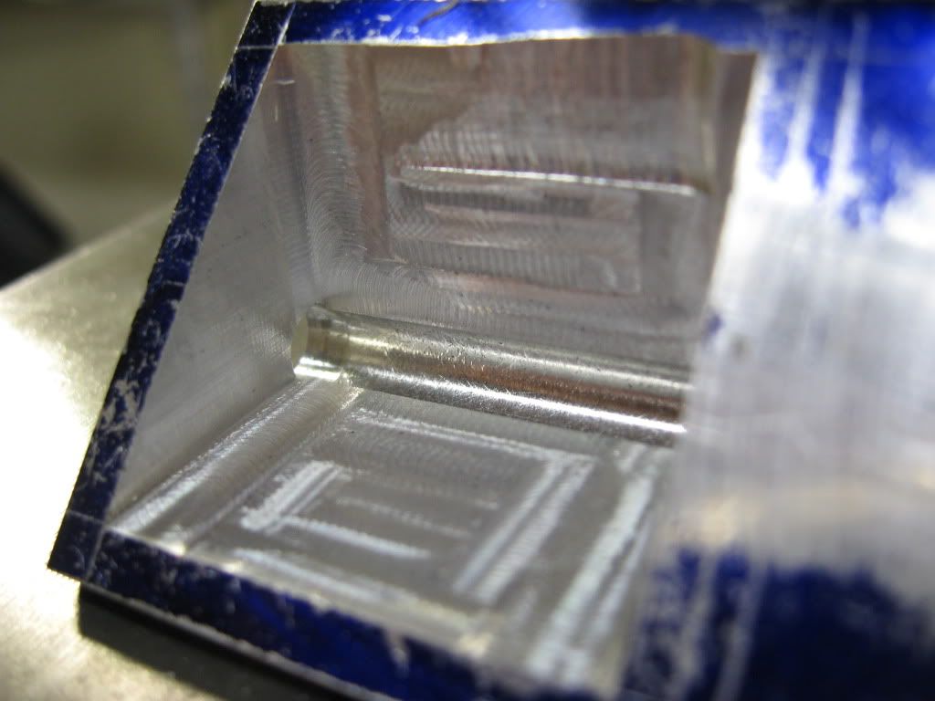
Drilled .201 hole about 5/8 of the way down. turned the block over and center drilled the other side and drilled again till the holes meet and a little further.
IMG_0672.jpg


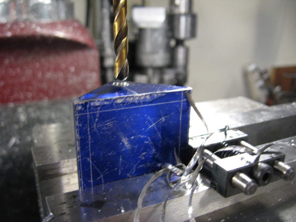
Then the 7/32 reamer came out. I went through the hole block one shot with the reamer
IMG_0673.jpg


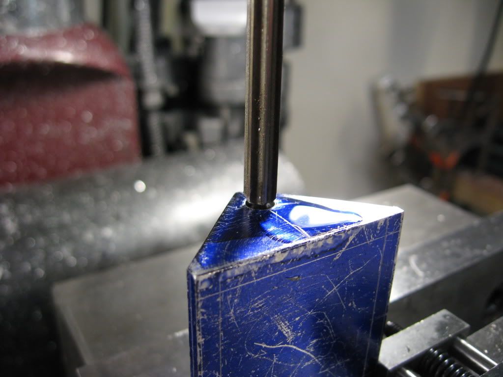
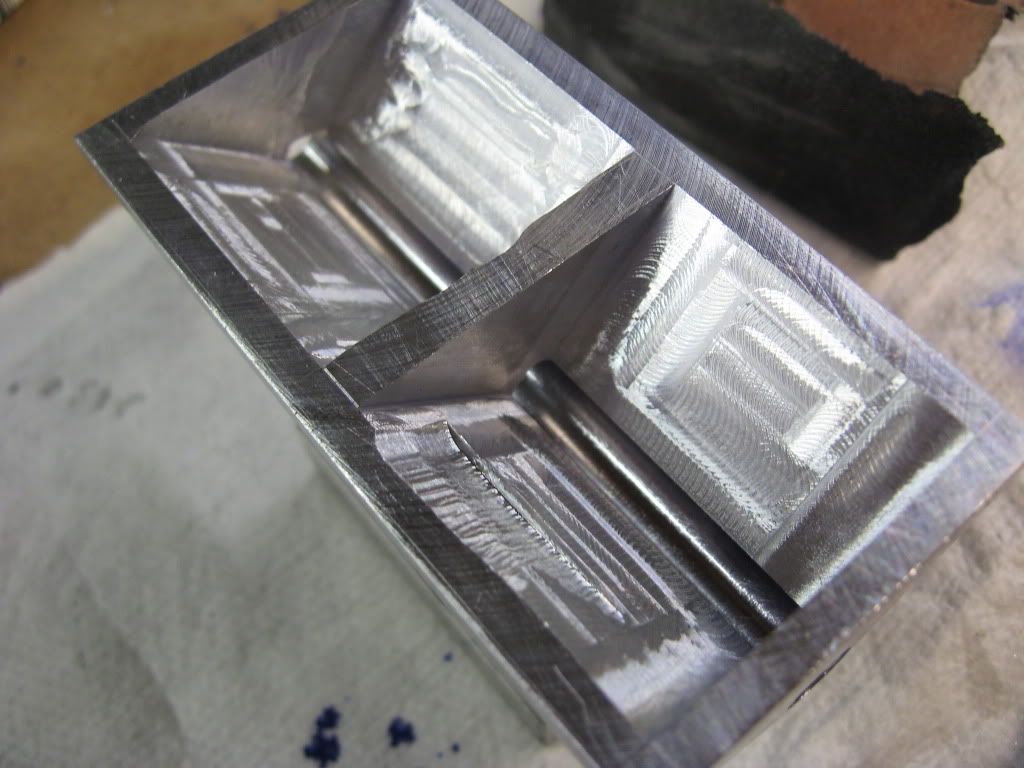
Then spot faced a 1/4" dia at rear of block for the larger bearing
IMG_0674.jpg


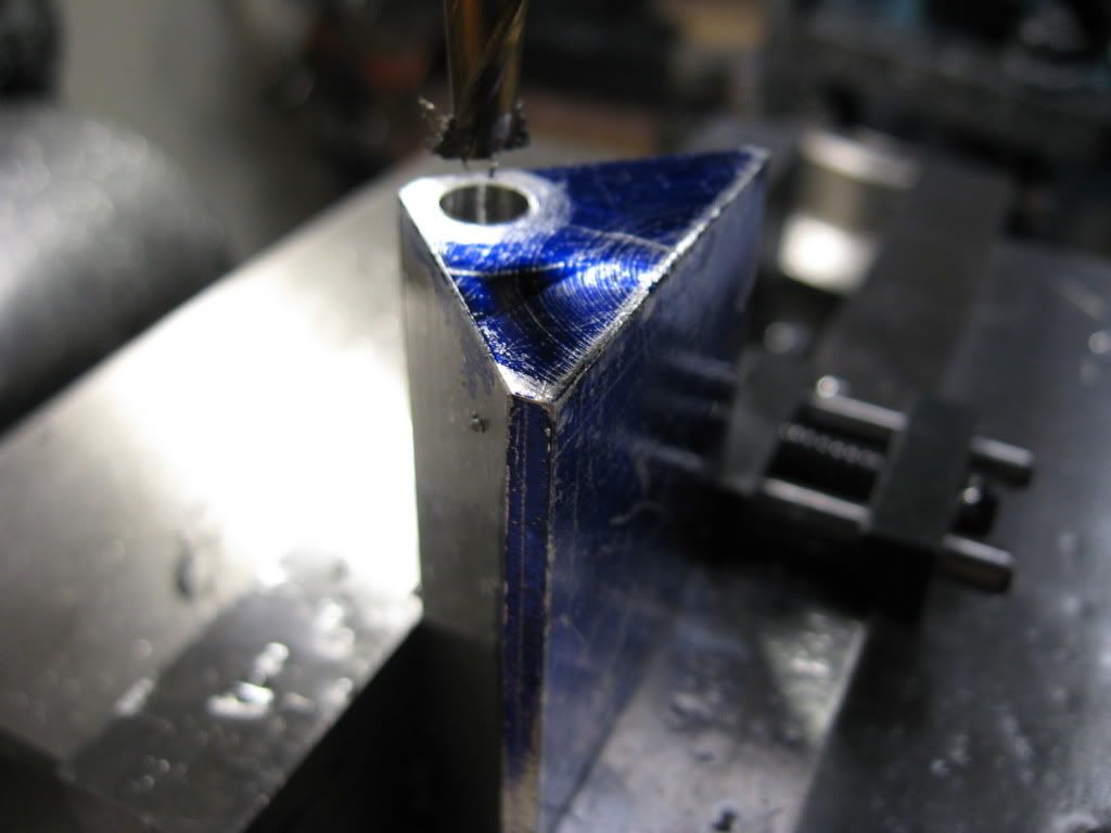
Now this is where the head scratchin comes in.....no center support bearing??? The plans just show a front and rear bearing????
There has got to be a center support bearing.

Gail, am I missing something??

Before I break this set up down I need to figure something out. I wish EW did an assy drawing or a cross section through the vitals.

Thanks
Tony

 
Did you see the CAD model on youtube? It appears there is a bearing journal in the middle of the crank.
 
Tony,
The center bearing is on the plan. The front and rear of the crankcase is separated by a 0.150 web shown on the bottom view of the part. That is the view that sits at a 45 degree angle on the plan. Section A-A is the view through that web. The camshaft center bearing is just the 7/32 hole in the web. One half of the center crankshaft bearing is also in this web with the other half in the bearing cap shown as part of section A-A. Does this help?
Gail in NM
 
dieselpilot, I haven't seen the you tube model, I'll have to look

Gail, Yes I know of the web there but the cam will be spinning on alum.. No bronze? Same for the crank too. I've been studying it and if I go to the web from the back with a 1/4" there will be little "meat for the push rod guides to have.

I guess that's it then, Thanks Gail And Diesel, I do have a tendency to over engineer.

Tony
 
[ame]http://www.youtube.com/watch?v=ZPl1cdllUMQ[/ame]

It's kind of quick, but nicely done.
 
Tony, does this engine have pressurized oil, or is it splash lube?
The video fellow really has his running up! That's what made me wonder about the oil.

Dean
 
Hi Dean,
First I sent you a site to buy the right wood for your engine. It's in your thread, NO BALSA!

This is a glow engine, methol alcohol nitro methane and castor oil is the fuel mix. It's more of a mist like a 2 cycle

Tony
 
Oh, I get it now, and probably would have earlier if I'd remembered back to the beginning of the thread.
Quite familiar with glow engines. So many images of the "oil pan" overloaded my little brain! Got stuck in paradigm neutral.

NO BALSA! Gotcha twice. Thanks.
I may have mentioned I'm not a wood kind of guy. Glad to take your, and my other fellow builder's word on it.
No balsa.


No balsa.


Dean
 
dieselpilot, Thanks for the animation. By the way it goes I should be done tomorrow :big:

Dean, That's alright I was burning out on oil pans too. I'm just not so crazy about steel spining on alum no matter what the lube. But I'll have to live with it.

Well a minus .219 gage pin fits perfect and slowly slides through the hole. I'm a happy guy. Tomorrow the hoggen will start on the upper crankcase (I know this excites everyone)

Tony
 
Tony,
I put this post up a half hour ago and it disappeared into the wild blue I guess. I will see what I can remember.

As far a lubrication. The bottom end is by splash lubrication. There is a breather tube mounted on the rear bearing housing, but it works through the rear bearing. As far as I know, the engine in inverted and 5cc of oil is put in through the oil drain plug. As there is no way to check the oil level, I assume that the oil is drained and replaced with a fresh charge of 5cc.

I think the alum/steel for the center bearings is OK. There is 0.003 clearance on the crankshaft center main, so there should not be a lot of contact. just enough to take care of crankshaft bending.

Not that you probably care at this point, but I used a different procedure to machine the center crankshaft bearing so I would not have to line bore it. I left some meat on the upper crankcase half and milled away enough to install the center bearing cap. Then I drilled and reamed through the entire length. Later when the crankcase halves were put together I indicated on the holes at each end and machined the recess for the end bearing retainers. Then the upper crankcase half was cleaned out on the inside and the rest of the details put in.

Look at the photos Crankcase2 and Crankcase3 at:
http://s338.photobucket.com/albums/n404/NMSteam/WhittleV8/

Gail in NM
 
Hi Gail,
Thanks for the info. I noticed the way you made the case in an earlier previous post. I'm not going to make the tool EW shows on the prints. I'm going to go with a "D" reamer in the middle and cut the ends to fit the bearing. I think this would be a lot easier than his line bore tool.

Tony
 
Another night of hoggen. I figured I wouldn't bore you with all the details, so here's a few quick picks.
Tomorrow I'll bring it to spec.

IMG_0685.jpg


IMG_0689.jpg


IMG_0693.jpg


2CYL4STROKE said:
Thm: Awesome job and without cnc machine

Heh. What's cnc?
;)


Looks like you had a good 'n hoggen day!
You must have quite a pile of chips by now.

Dean
 
Dean,
I got chips in my shirt pocket, my hair, my shoes and everywhere else. I need a major chip sweep up and machine cleaning. You'd think my floor was made out of alum. :big:
Tomorrow night I'll bring the oil pan and upper case to spec on the inside drill and tap joining holes and move on to the next part. Oh I have to bore the front and rear to accept the main bearing holders......more swarf drill the cyl holes, lifter holes and head bolt holes....more swarf..... should I even bother to clean up!?

Tony
 
Tony, I've got the same predicament as you, aluminum chips all over the place. I have compressed air in my shop and I blow my clothes off before I come upstairs but it seems like I still find chips where my wife thinks they shouldn't be. That video of the engine running makes my want to build one but I have my hands full with my current project. Maybe next year! Keep up the good work.
gbritnell
 
I guess chips are a part of life, with what we do, Tony. I used to get an itch or feel something biting me once in a while, sometimes even with a fresh shirt first thing in the morning. Chips in my shirt pockets! They don't come out in the wash.
Now, I put a piece of masking tape over my pockets when I go in the shop.
I also comb out my hair and beard well before I leave the shop for the shower. If I don't, I end up with chips in the bathtub. Hard on the feet!

Dean
 
Simple soultions to all you problems:

Wear you tee shirts inside out.

Wear a shop apron.

Wear a baseball cap.

Reduce your speed.

Reduce your feed.

Make a chip shield.

Use a chip shield.

Stand back when the chips are flying.

Buy a power feed and leave the shop when the chips are flying.

All of the above works for me. 8)

-MB
 
gbritnell, Deanofid, I know what you mean. I have air at my machines at 30psi and the main air at 80psi. I blow myself off with the 80 but there is always a chip stuck somewhere that follows me around the house :big:

Metal Butcher, All of what you said is true and I do have a power feed but......this engine is so small that when you are doing the intricate work (going an 1" with a 1/4" end mill) it's like working a sewing machine rather than a mill. I do have a smock but I feel like I should be cutting hair instead of metal :big:

Tony
 

Latest posts

Back
Top